PHYSICSSS
Unit 1: Kinematics (copy)
Distance and Displacement
Distance and displacement are two important concepts in physics that describe the position of an object in space. While they may seem similar, they have distinct differences.
Distance
Distance is the total length of the path traveled by an object.
It is a scalar quantity, meaning it has only magnitude and no direction.
Distance is measured in units such as meters, kilometers, or miles.
Distance is not used as much as Displacement in the AP exam, but it is denoted by the letter s or x
Displacement
Displacement is the change in position of an object from its initial position to its final position.
It is a vector quantity, meaning it has both magnitude and direction.
Displacement is measured in units such as meters, kilometers, or miles, and is represented by a vector with an arrow pointing from the initial position to the final position.
Vector and Scalar Quantities
Scalar Quantities
Scalar quantities are physical quantities that have only magnitude and no direction.
Examples of scalar quantities include mass, temperature, time, speed, distance, energy, and power.
Scalar quantities are represented by a single number and are usually measured in units such as kilograms, seconds, meters, and joules.
Vector Quantities
Vector quantities are physical quantities that have both magnitude and direction.
Examples of vector quantities include displacement, velocity, acceleration, force, and momentum.
Vector quantities are represented by a vector, which is a quantity that has both magnitude and direction.
Vectors are usually represented graphically as arrows, where the length of the arrow represents the magnitude of the vector and the direction of the arrow represents the direction of the vector.
Vector quantities can be added and subtracted using vector algebra, which takes into account both the magnitude and direction of the vectors.
Position, Velocity, and Acceleration
Position
Position is the location of an object relative to a chosen reference point. It is a vector quantity that can be described using distance and direction. Typically, a coordinate system is used to show where an obejct is located.
To determine which way an object is moving look at which way the Position vs Time Graph is sloped
The slope of a Position vs Time Graph is equal to velocity
When the slope is a straight line it has constant velocity
When the slope is a curved lived there is a change in velocity (acceleration)
When the slope is zero the object is at rest
The y-intercept is the initial position of the object
Speed vs Velocity
Speed and velocity are both terms used to describe the motion of an object, but they have different meanings.
Speed
Speed is a scalar quantity that refers to how fast an object is moving. It is calculated by dividing the distance traveled by the time taken to travel that distance. The SI unit of speed is meters per second (m/s).
Scalar quantity
SI Unit: Meters (m)/Seconds (s)
Equation: S = D/t
Velocity
Velocity is a vector quantity that refers to the rate at which an object changes its position. It is calculated by dividing the displacement of an object by the time taken to travel that displacement. The SI unit of velocity is meters per second (m/s).
Vector quantity
SI Unit: Meters (m)/Seconds (s)
Equation: V = x/t
A position vs time graph depicts velocity and a velocity vs time graph depicts acceleration.
Acceleration
Acceleration is the rate of change of velocity with respect to time. It is a vector quantity, which means it has both magnitude and direction. In AP Physics 1, acceleration is an important concept that is used to describe the motion of objects.
Calculating Acceleration
The formula for acceleration is:
a = (v_f - v_i) / t
where a is acceleration, v_f is final velocity, v_i is initial velocity, and t is time.
Units of Acceleration
The SI unit of acceleration is meters per second squared (m/s^2). Other common units of acceleration include feet per second squared (ft/s^2) and kilometers per hour squared (km/h^2).
Positive and Negative Acceleration
When an object is speeding up, its acceleration is positive. When an object is slowing down, its acceleration is negative. If an object is moving in the opposite direction of its acceleration, the acceleration is also negative.
Uniform Acceleration
Uniform acceleration is when an object's acceleration is constant over time. This means that the object's velocity changes by the same amount in each unit of time. The formula for uniform acceleration is:
a = (v_f - v_i) / t = (d/t) / t = d / t^2
where d is the distance traveled.
Non-Uniform Acceleration
Non-uniform acceleration is when an object's acceleration changes over time. This means that the object's velocity changes by different amounts in each unit of time. The formula for non-uniform acceleration is more complex and requires calculus.
Free Fall
Free fall is a special case of uniform acceleration where an object is falling under the influence of gravity. The acceleration due to gravity is approximately 9.8 m/s^2 near the surface of the Earth. The formula for free fall is:
d = (1/2)gt^2
where d is the distance fallen, g is the acceleration due to gravity, and t is time.
Uniformly Accelerated Motion and the BIG FIVE
Uniformly Accelerated Motion
Uniformly accelerated motion is a type of motion where the acceleration of an object remains constant.
The velocity of the object changes at a constant rate.
The acceleration can be positive or negative depending on the direction of the motion.
The BIG FIVE Equations of Motion
The BIG FIVE equations of motion are a set of equations that describe the motion of an object under uniformly accelerated motion.
These equations relate the initial velocity, final velocity, acceleration, displacement, and time of an object.
The equations are:
v = u + at
s = ut + 1/2at^2
v^2 = u^2 + 2as
s = 1/2(u + v)t
a = (v - u)/t
Here,
u = initial velocity
v = final velocity
a = acceleration
s = displacement
t = time
Example
Suppose a car starts from rest and accelerates uniformly at 5 m/s^2 for 10 seconds. Find the final velocity and displacement of the car.
Using the BIG FIVE equations of motion, we can find:
v = u + at = 0 + 5*10 = 50 m/s
s = ut + 1/2at^2 = 010 + 1/25*10^2 = 250 m
Therefore, the final velocity of the car is 50 m/s and the displacement is 250 m.
Projectile Motion and Angled Motion
Projectile Motion
Projectile motion is the motion of an object that is thrown or launched into the air and then moves under the influence of gravity.
The path of a projectile is a parabolic curve.
The horizontal and vertical components of motion are independent of each other.
The acceleration due to gravity acts only in the vertical direction.
Equations of Projectile Motion
The horizontal component of velocity is constant.
The vertical component of velocity changes due to the acceleration due to gravity.
The time of flight is the time taken by the projectile to reach the ground.
The maximum height reached by the projectile is given by the formula:
h = (v₀sinθ)² / 2gThe range of the projectile is given by the formula:
R = v₀²sin2θ / g
Angled Motion
Angled motion is the motion of an object that is thrown or launched at an angle to the horizontal.
The path of an angled projectile is a parabolic curve.
The horizontal and vertical components of motion are dependent on each other.
The acceleration due to gravity acts in both the horizontal and vertical directions.
Equations of Angled Motion
The horizontal component of velocity is given by:
v₀cosθThe vertical component of velocity is given by:
v₀sinθ - gtThe time of flight is given by:
t = 2v₀sinθ / gThe maximum height reached by the projectile is given by:
h = (v₀sinθ)² / 2gThe range of the projectile is given by:
R = v₀²sin2θ / g
Note: v₀ is the initial velocity, θ is the angle of projection, g is the acceleration due to gravity, and t is the time taken.
Unit 2: Newton's Laws of Motion
2.1: Newton's Laws of Motion: First and Second Law
Newton's First Law of Motion
Also known as the law of inertia
States that an object at rest will remain at rest, and an object in motion will remain in motion with a constant velocity, unless acted upon by an external force
Inertia is the tendency of an object to resist changes in its motion
The greater the mass of an object, the greater its inertia
This law is important in understanding the behavior of objects in the absence of external forces, such as in space or in a vacuum
It also explains why seat belts are important in cars, as they prevent passengers from continuing to move forward at the same speed when the car suddenly stops
This law is the basis for the concept of momentum, which is the product of an object's mass and velocity
First Law Sample Problem
What net force is required to maintain a 5,000 kg object moving at a constant velocity of magnitude 7,500 m/s?
Solution
The First Law says that any object will continue in its state of motion unless a force acts on it.
Therefore, no net force is required to maintain a 5,000 kg object moving at a constant velocity of magnitude 7,500 m/s.
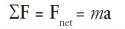
Here’s another way to look at it: Constant velocity means a = 0, so the equation Fnet = ma immediately gives Fnet = 0.
Newton's Second Law of Motion
Newton's Second Law of Motion states that the acceleration of an object is directly proportional to the force applied to it and inversely proportional to its mass.
The formula for Newton's Second Law of Motion is F = ma, where F is the force applied, m is the mass of the object, and a is the acceleration produced.
This law is also known as the law of acceleration.
The direction of the force applied determines the direction of the acceleration produced.
The greater the force applied, the greater the acceleration produced, and the greater the mass of the object, the smaller the acceleration produced.
This law is used to calculate the force required to move an object of a certain mass at a certain acceleration.
A force of 1 kg·m/s 2 is renamed 1 newton
Newton's Second Law of Motion is essential in understanding the behavior of objects in motion and is used in various fields such as engineering, physics, and sports.
Second Law Sample Problem
How much force is required to cause an object of mass 2 kg to have an acceleration of 4 m/s 2?
Solution
According to the Second Law,
Fnet = ma = (2 kg)(4 m/s 2 ) = 8 N.
Friction Force
Friction force is a force that opposes motion between two surfaces that are in contact.
It is caused by the irregularities in the surfaces that come into contact with each other.
The force of friction acts parallel to the surfaces in contact and in the opposite direction to the direction of motion or the applied force.
There are three types of friction:
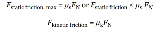
Static Friction: It is the friction that exists between two surfaces that are not moving relative to each other. The static friction force is equal and opposite to the applied force until the applied force exceeds the maximum static friction force, after which the object starts moving.
Kinetic Friction: It is the friction that exists between two surfaces that are moving relative to each other. The kinetic friction force is constant and is less than the maximum static friction force.
Rolling Friction: It is the friction that exists between a rolling object and the surface it is rolling on. Rolling friction is less than static and kinetic friction.
The factors that affect friction are:
Nature of the Surfaces: The nature of the surfaces in contact affects the friction force. Rough surfaces have more friction than smooth surfaces.
Normal Force: The normal force is the force exerted by a surface perpendicular to the surface in contact. The friction force is directly proportional to the normal force.
Surface Area: The surface area in contact affects the friction force. The larger the surface area in contact, the greater the friction force.
The strengths of these two types of friction forces are given by the following equations:
Weight
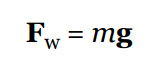
The weight of an object is the gravitational force exerted on it by a gravitational field.
Mass is an intrinsic property of an object that measures its inertia. An object’s mass does not change with location.
Since weight is a force, we can use F = ma to compute it, where the acceleration is the gravitational force imposed on an object. Therefore, setting a = g, the equation F = ma becomes
The Normal Force
The component of the contact force that’s perpendicular to the surface is called the normal force on the object.
The normal force comes from electrostatic interactions among atoms.
The normal force is what prevents objects from falling through tabletops or you from falling through the floor.
The normal force is denoted by FN, or simply by N.
2.2: Uniform Circular Motion
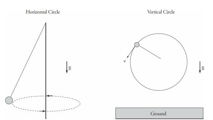
Uniform circular motion is the motion of an object moving in a circular path at a constant speed. The direction of the velocity of the object is constantly changing, but the magnitude of the velocity remains constant.
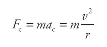
In order for an object to move in a circular path, there must be a force acting on it towards the center of the circle. This force is called the centripetal force. The magnitude of the centripetal force is given by the equation:
F = (mv^2)/rwhere F is the centripetal force, m is the mass of the object, v is the speed of the object, and r is the radius of the circle.
Centrifugal force is a fictitious force that appears to act on an object moving in a circular path. It is not a real force, but rather an apparent force that arises from the fact that the object is moving in a curved path. The centrifugal force is equal in magnitude and opposite in direction to the centripetal force.
The following diagrams show examples of a ball on a string traveling in a horizontal circle and a vertical circle.
UCM Sample Problem
Example 1
An object of mass 5 kg moves at a constant speed of 6 m/s in a circular path of radius 2 m. Find the object’s acceleration and the net force responsible for its motion.
Solution
By definition, an object moving at constant speed in a circular path is undergoing uniform circular motion. Therefore, it experiences a centripetal acceleration of magnitude v 2/r, always directed toward the center of the circle:
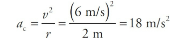
The force that produces the centripetal acceleration is given by Newton’s Second Law, coupled with the equation for centripetal acceleration:
Example 2
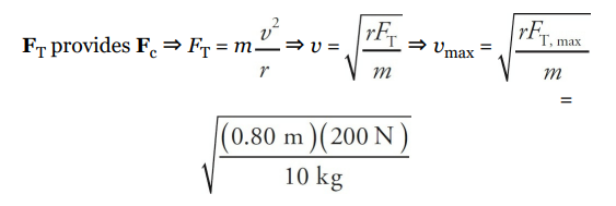
A 10 kg mass is attached to a string that has a breaking strength of 200 N. If the mass is whirled in a horizontal circle of radius 80 cm, what maximum speed can it have? Assume the string is horizontal.
Solution
The first thing to do in problems like this is to identify what force(s) provide the centripetal force. In this example, the tension in the string (FT ) provides the centripetal force (Fc):
2.3: Newton's Third Law of Motion
Newton's Third Law of Motion states that for every action, there is an equal and opposite reaction.
This means that when an object exerts a force on another object, the second object exerts an equal and opposite force back on the first object.
The forces are always of the same type, either both are attractive or both are repulsive.
The Third Law applies to all types of forces, including gravitational, electromagnetic, and nuclear forces.
The Third Law is important in understanding how objects move and interact with each other.
It explains why rockets are able to launch into space and why cars are able to move forward.
The Third Law also helps explain why collisions occur and how they affect the objects involved.
It is important to note that the forces in the Third Law always act on different objects, not on the same object.
Pulleys
Pulleys are devices that change the direction of the tension force in the cords that slide over them.
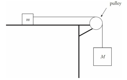
Pulley Sample Problem
In the diagram above, assume that the tabletop is frictionless. Determine the acceleration of the blocks once they’re released from rest.
Solution
There are two blocks, so draw two free-body diagrams: The positive directions for each block must coincide. If the block on the table travels to the right then the hanging block travels down. This is why down is positive for the hanging block.
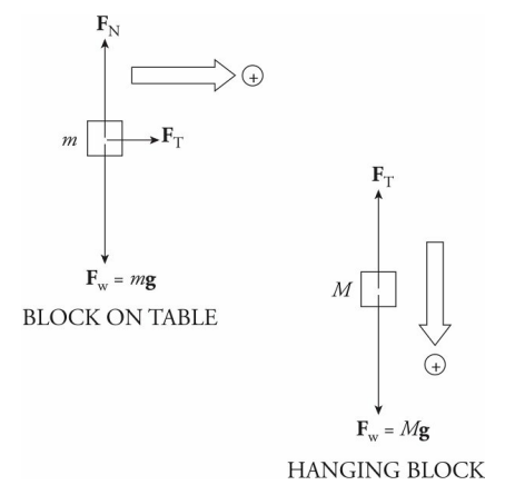
To get the acceleration of each one, we use Newton’s Second Law, Fnet = ma. Notice that while Fw = FN for the block on the table, Fw does not equal FT for the hanging block, because that block is in motion in the downward direction.
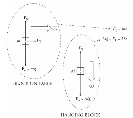
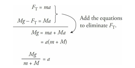
Note that there are two unknowns, FT and a, but we can eliminate FT by adding the two equations, and then we can solve for a.
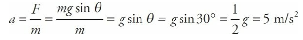
Inclined Planes
An inclined plane is basically a ramp. If an object of mass m is on the ramp, then the force of gravity on the object, Fw = mg, has two components: One that’s parallel to the ramp (mg sin θ) and one that’s normal to the ramp (mg cos θ), where θ is the incline angle.
The force driving the block down the inclined plane is the component of the block’s weight that’s parallel to the ramp: mg sin θ.
When analyzing objects moving up or down inclined planes it is almost always easiest to rotate the coordinate axes such that the x-axis is parallel to the incline and the y-axis is perpendicular to the incline, as shown in the diagram.
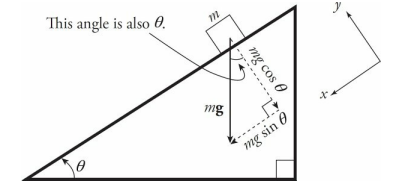
The object would accelerate in both the xand y-directions as it moved down along the incline if you did not rotate the axis. However, with the rotated axes, the acceleration in the y-direction is zero. Now we only have to worry about the acceleration in the x-direction.
Inclined Planes Sample Problem
A block slides down a frictionless inclined plane that makes a 30° angle with the horizontal. Find the acceleration of this block.
Solution
Let m denote the mass of the block, so the force that pulls the block down the incline is mg sin θ, and the block’s acceleration down the plane is
Chapter 3 - Electric Force, Field, and Potential
Electric Charge
Units of charge: Coulombs (C)
One proton has a charge of 1.6 x 10^-19 C
One electron has a charge of -1.6 x 10^-19
When an object has more protons than electrons, it’s positively charged
When an object has more electrons than protons, it’s negatively charged
Like charges repel and opposite charges attract
Quanta = the smallest package of a proton or electron that charge comes in
Atomic Structure
Atoms have protons (and neutrons) in the middle and electrons zipping around outside
Electrons are easier to remove and in static electricity, we assume only electrons are being removed/added
- The initial charge of the system will always equal the final charge of the system
Conductors vs insulators
Generally, metals are good conductors and nonmetals are insulators
Conductors - allow charge to move easily through them
Insulators - don’t allow charge to move easily through them (held in place)
There are 3 ways to charge an object:
Charging by Friction - rubbing two objects like a fuzzy towel and iron rod results in electrons jumping from one object to the other
Remember that net charge of the towel-rod system is still the same
Charging by Contact or Conduction
When a charged object comes in contact with a neutrally charged object, the electrons disperse so that both objects have the same charge sign
Bigger objects end up with more charge because they have more room
Insulators don’t allow as much charge to disperse through contact as conductors do
Induced Charge, Polarization, and Induction
Induced charge - a neutrally charged object becomes polarized (electrons clump up on one side of the object and positive charges pile on the other side)
In AP Physics 2 questions, a grounding wire is often included
The grounding wire essentially serves as an escape route for charges to escape from the polarized object
Charge Distribution
On conductors, excess charges are pushed to the outside of the object to get away from each other
On insulators, excess charges stay where they are and don’t disperse
Electric Fields
Field: a property of a region that can apply force to objects found in that space
Electric fields affect charged particles only
Charged particles in electric fields experience an electric force
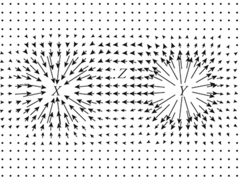
Electric fields are drawn as arrows because they’re vectors
The longer the arrows, the greater the magnitude of the electric field
Units of electric fields: N/C (Newtons/Coulomb)
F = qE
F: electric force
q: charge
E: electric field
The direction of the force on a positive charge is the same direction as the electric field
The direction of the force on a negative charge is the opposite direction as the electric field
Typically, when using the equation F = qE, we solve for the magnitude and find the direction of the electric force and/or field afterward
Electric Potential
Electric potential: Electric potential energy per unit charge (provided by an electric field)
Units: 1 V = 1 J/C
Electric potential is scalar (only have magnitudes)
“Zero of electric potential” = “ground” = a theoretical distance at which two charged particles are infinitely far away from each other and therefore don’t affect each other
==ΔU = qΔV==
ΔU = difference in electric potential energy
q = charge
ΔV = difference in electric potential
Equipotential lines: Lines on which a charged particle would have the same potential
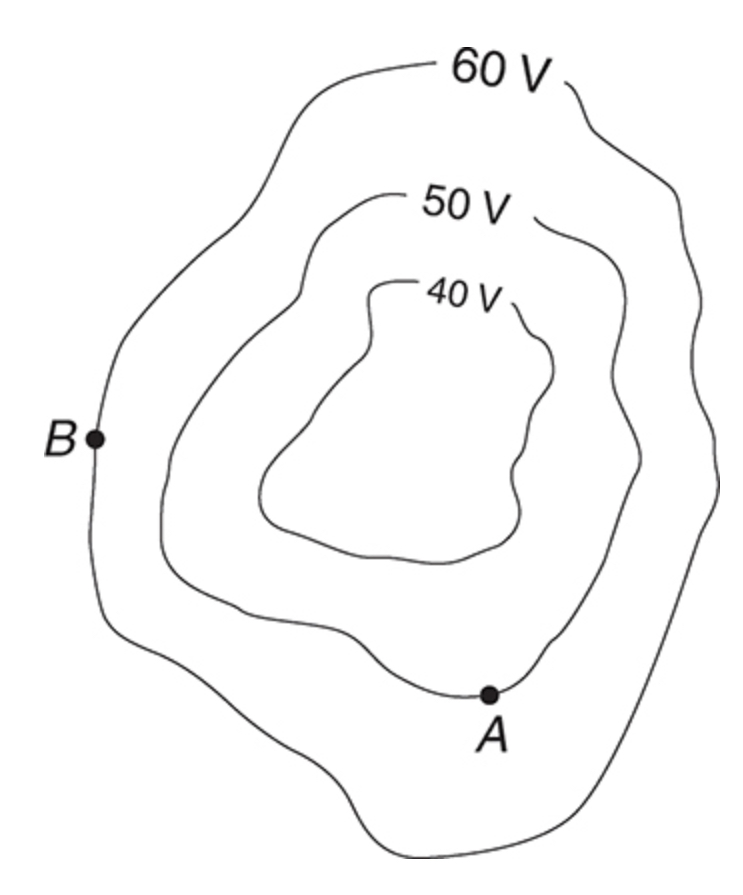
Equipotential lines are drawn perpendicular to the electric field lines
It takes energy to move a charge to another equipotential line
Positive charges are naturally pulled to areas of negative potential
Negative charges are naturally pulled to areas of positive potential
Remember that energy is conserved so U + K is constant
U is electric potential energy and K is kinetic energy
Electrostatics
Parallel Plates
There are 2 metal plates that are parallel - one is positively charged and the other is negatively charged
This creates a uniform electric field with the arrows pointing from the positive plate to the negative plate
==E = ΔV/Δr==
E = the magnitude of the electric field
ΔV = the magnitude of the voltage difference between plates
Δr = the distance between plates
Parallel plates can be used to make capacitors (a device that stores charges and will be further explored in circuits)
==ΔV = Q/C==
ΔV = the voltage across plates
Q = charge on each plate
C = the capacitance of the capacitor
==C = kεA/d==
C = capacitance
k = dielectric constant - shows how good of an insulator you have between plates
ε = “vacuum permittivity” = 8.85 x 10^-12 C/Vm
Point charges
==E = q/(4πεr) = kq/r==
k = Coulomb’s Law Constant = 9 x 10^9 Nm^2/C^2
The electric field produced by a positive charge points away from the charge
The electric field produced by negative charge points toward the charge
==V = kq/r==
==F = kqq/r^2==
Where the two q’s are the charges of two point charges
k = Coulomb’s Law Constant
r = the distance between the two point charges
Electric Field around a point charge or conducting sphere
==E = kq/r^2==
To solve for the magnitude of the electric field
Inside a conducting sphere, the electric field is 0
Net force on any charge inside a conducting sphere is 0
Unit 4: Energy
Work and Mechanical Energy
Work
When you lift a dumbbell from the floor, you exert a force on it over a distance, and when you push a box across a floor, you also exert a force on it over a distance. The application of force over a distance is called work. Work is a scalar quantity and is measured in units of J (joules).
Work is the transfer of energy that occurs when a force is applied over a distance.
The formula for work is W = Fd, where W is work, F is force, and d is distance.
Work is measured in joules (J).
Work at an Angle
The previous formula only works when work is done completely parallel to the intended distance of travel. When the force is done at an angle, the formula becomes:
W = Fd cos θExample: A force is applied to a block at an angle of 30 degrees to the horizontal. The force has a magnitude of 50 N and the block is displaced by 2 meters in the direction of the force. Using the equation that relates work, force, displacement and the angle between the force and displacement, we can find the work done on the block, which is equal to the force times the displacement times the cosine of the angle between them. Thus, the work done on the block is 86.6 J.
Mechanical Energy
Mechanical energy is the sum of kinetic energy and potential energy in a system.
Kinetic energy is the energy of motion and is given by the formula KE = 1/2mv^2, where m is mass and v is velocity.
Potential energy is the energy stored in an object due to its position or configuration and is given by the formula PE = mgh, where m is mass, g is acceleration due to gravity, and h is height.
Mechanical energy is conserved in a closed system, meaning that the total amount of mechanical energy remains constant.
Work-Energy Theorem
The work-energy theorem states that the net work done on an object is equal to the change in its kinetic energy.
The formula for the work-energy theorem is Wnet = ΔKE, where Wnet is the net work done on an object and ΔKE is the change in its kinetic energy.
The work-energy theorem can be used to calculate the work done on an object or the change in its kinetic energy.
Wtotal = deltaKThe work-energy theorem begins to answer the question by stating that a system gains or loses Kinetic Energy by transferring it to through work between the environments.
Conservation of Mechanical Energy
In a closed system, the total amount of mechanical energy is conserved.
This means that the sum of kinetic energy and potential energy remains constant.
The conservation of mechanical energy can be used to solve problems involving the motion of objects in a system.
The sum of an object’s kinetic energy and potential energies is called its total mechanical energy
E = K + UKi + Ui = Kf + UfThis is the simplest form of the Law of Conservation on Total Energy.
Conservation of Energy with Nonconservative Forces
The equation
Ki + Ui = Kf + Ufholds if no nonconservative forces are doing work. However, if work is done by such forces during the process under investigation, then the equation needs to be modified to account for this work as follows:Ki + Ui + Wother= Kf + UfExample Questions:
Suppose a block of mass 2 kg is placed on a rough surface with an initial velocity of 5 m/s. The coefficient of kinetic friction between the block and the surface is 0.2. The block comes to rest after covering a distance of 10 m. Find the work done by frictional force.
Power
Power is the rate at which work is done or energy is transferred. It is a scalar quantity and is measured in watts (W). Power is the rate at which energy is transferred into, or out of, within a system,.
Formula
The formula for power is:
P = W/twhere P is power, W is work, and t is time.
Units
The SI unit for power is watts (W), which it was originally (Joules/s) later renamed the watt. Other common units include horsepower (hp) and kilowatts (kW).
Calculations
To calculate power, you need to know the amount of work done and the time it took to do it. For example, if a person lifts a 50 kg weight 2 meters in 5 seconds, the work done is:
W = mgh
W = (50 kg)(9.8 m/s^2)(2 m)
W = 980 J
The power can then be calculated using the formula:
P = W/t
P = 980 J / 5 s
P = 196 W
Therefore, the power output of the person lifting the weight is 196 watts.
Power and Energy
Power and energy are related, but they are not the same thing. Energy is the ability to do work, while power is the rate at which work is done. The amount of energy used depends on both the power and the time it is used for. For example, a 100 W light bulb left on for 10 hours uses more energy than a 50 W light bulb left on for the same amount of time.
Power and Efficiency
Efficiency is a measure of how much of the input energy is converted into useful output energy. The efficiency of a device can be calculated using the formula:
efficiency = useful output energy / input energyPower is also related to efficiency. The higher the power output of a device, the more energy it can convert into useful work. However, a device with a high power output may not necessarily be more efficient than a device with a lower power output.
Unit 5: Momentum
What is momentum?
Momentum is the degree of an object's opposition to a modification in motion. It is a vector quantity, indicating it has both size and direction. The momentum formula is p = mv, where p is momentum, m is mass, and v is velocity. This unit accounts for 12-18% of the exam weight.
Momentum and Impulse
Momentum
Momentum is a measure of an object’s resistance to a change in motion, which is defined as the product of an object’s mass and velocity. It has both magnitude and direction.
Momentum is a property of a moving object that is equal to the product of its mass and velocity.
It is a vector quantity, meaning it has both magnitude and direction.
The unit of momentum is kg m/s.
The formula for momentum is:
p = mv, where p is momentum, m is mass, and v is velocity.Momentum is conserved in a closed system, meaning the total momentum of the system before a collision is equal to the total momentum after the collision.
Impulse
Impulse is the change in momentum of an object over a given time period. It is the product of the force applied to an object and the time over which the force is applied.
Impulse is the change in momentum of an object over a period of time.
It is also a vector quantity.
The unit of impulse is Ns (newton-second).
The formula for impulse is:
J = FΔt, where J is impulse, F is the force applied, and Δt is the time interval over which the force is applied.Impulse is equal to the area under a force-time graph.
Conservation of Linear Momentum
Linear momentum is the product of mass and velocity of an object. According to the law of conservation of linear momentum, the total momentum of a system of objects remains constant if no external forces act on the system. This means that the sum of the momenta of all the objects in the system before a collision is equal to the sum of the momenta of all the objects after the collision.
This law is applicable to both elastic and inelastic collisions.
In an elastic collision, the total kinetic energy of the system is conserved, while in an inelastic collision, some of the kinetic energy is converted into other forms of energy, such as heat or sound.
The conservation of linear momentum is a fundamental principle in physics and is used to explain a wide range of phenomena, from the behavior of subatomic particles to the motion of planets in the solar system.
This law is also used in engineering and technology to design and analyze systems that involve the transfer of momentum, such as rockets, satellites, and automobiles.
The conservation of linear momentum is a consequence of the fundamental symmetry of nature known as translational symmetry, which states that the laws of physics are the same in all inertial reference frames.
The total linear momentum of an isolated ststem remains constant.

total Pinital = total Pfinal
Collisions
Collisions occur when two or more objects come into contact with each other. The following are some important concepts related to collisions:
Types of Collisions
There are three types of collisions:
Elastic Collisions: In an elastic collision, the total kinetic energy of the system is conserved. This means that the objects bounce off each other without losing any energy.
Inelastic Collisions: In an inelastic collision, the total kinetic energy of the system is not conserved. This means that the objects stick together after the collision and some energy is lost as heat or sound.
Perfectly Inelastic Collision: In an Perfectly Inelastic Collision, the objects stick together and travel in the same direction.
The image below represents these three types:
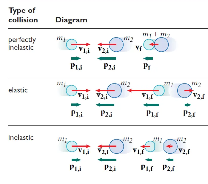
Collisions are an important concept in physics and have many real-world applications. Understanding the types of collisions, conservation of momentum, coefficient of restitution, and impulse can help in analyzing and predicting the behavior of objects in collisions.
Chapter 6 - Geometric and Physics Optics
Waves
Wave: an oscillation that transfers energy from one place to another
Transverse waves: particles in the wave move perpendicularly
Ex: wiggling a string up and down
Crest: top of the wave
Trough: bottom of the wave
Wavelength (λ): distance from crest to crest and from trough to trough
Amplitude (A): distance from a peak to the horizontal axis or from a trough to the horizontal axis
Frequency (f): Number of wavelengths that pass a given period in 1 second
Period (T): Time necessary for one wavelength to pass a given point
Wave equation: ==x = Acos(⍵t) = Acos(2πft)==
Longitudinal waves: particles move parallel to the direction of the wave’s motion
Interference
Constructive interference: when the peaks of one wave align with the peaks of another
Amplitudes add up
Amplitudes return to normal after the waves pass one another
Destructive interference: when the troughs of one wave align with the peaks of another
Amplitudes subtract
Amplitudes return to normal after the waves pass one another
Electromagnetic waves
Gamma Ray, X-Ray, UV Rays, Visible Light, Infrared, Microwave, Radiowaves
These types of EM waves are from shorter wavelength to longer wavelength
Higher frequency and energy to lower frequency and energy
All EM waves travel at the same speed: 3 x 10^8 m/s (c) = the speed of light
An oscillating electric field wave induces an oscillating magnetic field wave at a right angle to itself
The EM wave is self-propagating and can travel through a vacuum at the speed of light
EM waves are transverse
Polarization of light
Polarizing the E-field portion of the wave: move the charge back and forth in the horizontal direction
Polarized light that is reflected off of flat surfaces (like the light that causes road glare) is polarized horizontally
Longitudinal waves cannot be polarized
Diffraction: the property of waves to hear sounds around corners
Point-source model: each point on a wave is the starting spot for a new wave
Waves don’t just travel forward - they travel outwards as well
The smaller the wave is compared to the boundary, the less prominent the effects of diffraction will appear
This is why we don’t see around corners - we only hear
Single and Double Slits
When light is diffracted through 2 slits, a pattern of light and dark bands is created on the screen
Bright areas are where constructive interference occurred
Dark areas are where destructive interference occurred
==dsin(Θ) = mλ==
d: distance between slits
Θ: the angle an observer would have to look at the bright spot
m: “order” of the bright/dark spot
Bright spots: m = 1 (the bright spot immediately right/left of the central spot)
Dark spots: m = 0.5 (the dark spot immediately right/left of the central spot)
λ: wavelength
Diffraction gratings
Like the double-slit experiment but with multiple slits
The bright spots produced are sharper dots - locations for bright and dark spots are the same as the double slit
Single slit
Produces interference patterns because light hits each side of the slit
The central maximum is bright and wider than the double-slit experiments
The other bright spots are spaced the same but are dim
Index of Refraction
Index of refraction: the amount by which light slows down in a material
==n = c/v==
n: index of refraction
c: speed of light in a vacuum
v: speed of light through the specific material
Frequency doesn’t change when light speeds up or slows down
==λn = λ/n==
λn: wavelength of light traveling through transparent medium
λ: wavelength in a vacuum
n: index of refraction
Thin Films
Thin films such as a thin layer of oil on a puddle results in some light reflecting off the film and some penetrating the film
Constructive interference: 2t = mλ
t: the thickness of the film
m: how many extra wavelengths the light inside the film went
λ: wavelength in the film
Mirrors
Plane (flat) mirrors
The angle of incidence: angle from a ray hitting the mirror to a vertical axis
Angle of incidence = Angle of reflection
Image produced by plane mirrors are upright (virtual image)
The magnification is equal to 1 because the image and real object are the same size
Spherical mirrors
Principal axis: an imaginary horizontal axis running through the middle of the mirror
C: a point labeled C is the center of the sphere and is located a distance of r from the mirror
F: a point labeled F is the focal point of the mirror and is located a distance of f from the mirror
f = r/2
Rules for drawing rays:
Draw a ray that is parallel to the principal axis and reflects through the focal point
Draw a ray that foes through the focal point and reflects parallel to the principal axis
Any points that are on the same side of the mirror as the object are a positive distance from the mirror and any points on the opposite side of the mirror as the object are negative
==1/f = 1/so + 1/si==
f: focal length
so: distance from the object to the mirror
si: distance from the image to the mirror
==|M| = |hi/ho| = |si/so|==
M < 1: image is reduced in size
M > 1: image is enlarged in size
Images that stand upright are virtual images
Images that are upside down are real images
Convex mirror - diverging mirrors
Cannot produce real images
If the object is to the left of the mirror, the mirror is shaped like a C
Concave mirror - converging mirrors
If the object is to the left of the mirror, the mirror is shaped like a backward C
Snell’s Law: nsinΘ is constant
n: index of refraction
Θ: angle from the ray to a vertical axis
Total internal reflection: when the light ray is directed at or beyond the critical angle
Critical angle: angle past which rays can’t be transmitted to another material (reflects off of the boundary between materials
==sinΘ = n2/n1==
Θ: critical angle
n2: the second material’s index of refraction
n1: the first material’s index of refraction
Lenses
Convex lens: converging lens
Shaped like a sideways eye
Concave lens: diverging lens
Shaped like a rectangle that caved in on both sides
Rules for drawing rays for converging lens:
Draw a ray that is parallel to the principal axis and reflects through the far focal point (the one on the other side of the lens)
Draw an incident ray that goes through the near focal point and refracts parallel to the principal axis
1/f = 1/so + 1/si
|M| = |hi/ho| = |si/so|
Rules for drawing rays for diverging lens:
Draw an incident ray parallel to the principal axis and refract it as if it came from the near focal point (dotted line from the focal point to the point where the parallel segment of the ray intersects the lens and a solid line following that same path)
Draw an incident ray toward the far focal point that refracts parallel to the principal axis (a dotted line that continues the parallel line segment on the side of the object)
1/f = 1/so + 1/si
|M| = |hi/ho| = |si/so|
Unit 7: Quantum, Atomic, and Nuclear Physics
Photons and the photoelectric effect
Quanta: Light being emitted as individual packets of energy called quanta.
Photon: A quantum of electromagnetic energy is known as a photon
Photoelectric effect: light behaves like a stream of photons, and this is
illustrated by the photoelectric effect
Photoelectrons: the released electrons are known as photoelectrons
Wave theory of light predicted three results:
Significant time delay between the moment of illumination and the ejection of photoelectrons.
Increasing the intensity of the light could cause the electrons to leave the metal surface with greater kinetic energy.
Photoelectrons would be emitted regardless of the frequency of the incident energy, as long as the intensity was high enough.
These predictions were not observed.
As, photoelectrons were ejected within a few billionths of a second after illumination, disproving the prediction.
Increasing the intensity of the light did not cause photoelectrons to leave the metal surface with greater kinetic energy.
For each metal there was a certain threshold frequency
E = hf
h is the Planck’s constant = 6.63 x 10^-34 J/s.
Metal’s work function is the certain amount of energy that has to be imparted to an electron on the metal surface
Kmax = hf -ϕ
fo = ϕ/ h
SI unit for energy is the joule
Example
The work function, ϕ, aluminum is 4.08 eV
(a) What is the threshold frequency required to produce photoelectrons from
aluminum?
(b) Classify the electromagnetic radiation that can produce photoelectrons.
(c) If light of frequency f = 4.00 × 10¹⁵ Hz is used to illuminate a piece of
aluminum,
(i) what is Kmax, the maximum kinetic energy of ejected photoelectrons?
(ii) what’s the maximum speed of the photoelectrons? (Electron mass = 9.11×
10−31 kg.)
(d) If the light described in part (b) were increased by a factor of 2 in intensity,
what would happen to the value of Kmax?
The Bohr Model of the atom
The light from a glowing gas, passed through a prism to disperse the beam
into its component wavelengths, produces patterns of sharp lines called
atomic spectra.
R is Rydberg constant = 1.1 x 10^-7
The electron absorbs a certain amount of energy, and it is excited to a higher
orbit, emitting a photon in the process.
The wavelength of the photon
Example
The first five energy levels of an atom are shown in the diagram
below:
(a) If the atom begins in the n = 3 level, what photon energies could be
emitted as it returns to its ground state?
(b) What could happen if this atom, while in an undetermined energy state, were bombarded with a photon of energy 10eV?
Wave-Particle Duality
The electromagnetic radiation propagates like a wave but exchanges energy
like a particle. This is known as wave-particle duality.
De-Broglie Wavelength
Example
Electrons in a diffraction experiment are accelerated through a
potential difference of 200 V. What is the de Broglie wavelength of these
electrons?
The Wave Function
The probability that a particle will be measured to be at a particular position
when the position is measured. That probability is related to a new physical
parameter called the wave function.
Relativity
The Theory of relativity has only two postulates:
The results of physical experiments will be the same in any
non-accelerating reference frames.
The speed of light is constant
Time dilation:
Demonstrated by synchronized atomic clocks.
E.g: When a clock placed on a fast-moving airplane is compared to a clock at rest on the ground, the clock in the airplane shows that less time has passed than the time recorded by the clock on the ground.
This is known as time dilation.
Length Contraction:
To be consistent with time dilation, there must also be disagreement
Nuclear Physics
The nucleus of an atom is composed of particles, protons, and neutrons.
Protons + Neutrons = Nucleons
The number of protons in a given nucleus is called the atom’s atomic number
denoted by Z.
The total number of nucleons (Z+N), is called the mass number, and is
denoted by A.
Isotopes: The nuclei that contain the same numbers of neutrons are called
isotopes
Notation
Example
How many protons and neutrons are contained in the nuclide ?
Solution
The subscript (the atomic number, Z) gives the number of protons, which is
29. The superscript (the mass number, A) gives the total number of nucleons.
Since A = 63 = Z + N, we find that N = 63 − 29 = 34
The Nuclear Force
The strong nuclear force is a fundamental force that binds neutrons and
protons together to form nuclei.
Binding Energy
The masses of the proton and neutron:
Proton: 1.6726 x 10^-27 kg
Neutron: 1.6749 x 10^-27 kg
Mass defect: The difference between the mass of any bound nucleus and the
sum of the masses of its constituent nucleons is called the mass defect.
E = mc^2
Binding energy tells us how strongly the nucleus is bound
Example
What is the maximum wavelength of EM radiation that could beused to photodisintegrate a deuteron?
Solution
The binding energy of the deuteron is 2.23 MeV,
so a photon would need to have at least this much energy
to break the deuteron into a proton and neutron. Since E =
hf and f = c/λ
Nuclear Reactions
Nuclear fusion: It is of small nuclei at extremely high temperatures.
Nuclear fission: The emission of a particle or splitting of the nucleus
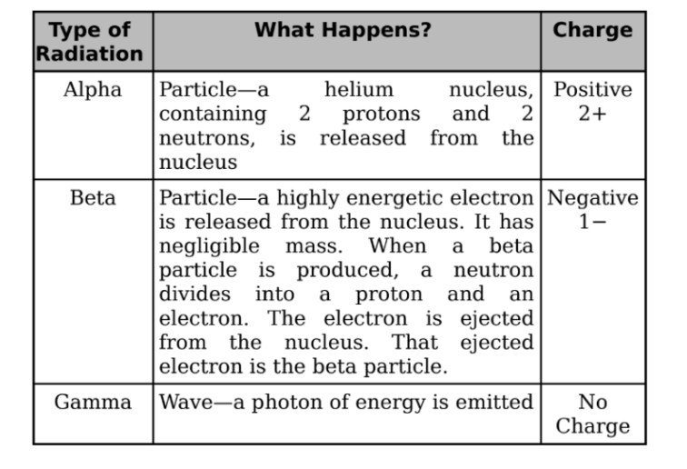
Alpha Decay
When a nucleus undergoes alpha decay, it emits an alpha particle, which
consists of two protons and two neutrons.
It is the same as the nucleus of a helium-4 atom.
An alpha particle can be represented as
Two important features of a nuclear reaction:
Mass number is conserved.
Charge is conserved.
The decaying nuclide is known as the parent.
The resulting nuclide is known as the daughter.
Beta Decay
There are three categories of beta decay, called β+, β−, and electron capture.
β− decay:
When the neutron-to-proton ratio is too large, the nucleus undergoes
β− decay.
It occurs when a neutron transforms into a proton and releases an
electron. The expelled electron is called a beta particle.
The transformation of a neutron into an electron and a proton, and
another particle called the electron antineutrino is caused by the
action of weak nuclear force.
β+ decay:
When the neutron-to-proton ratio is too small, the nucleus will undergo
β+ decay.
In this form of β+ decay, a proton is transformed into a neutron and a
positron, and another particle is called electron-neutrino.
Electron Capture:
In which a nucleus can increase its neutron-to-proton ratio to capture
an orbiting electron and then cause the transformation of a proton into
a neutron
Gamma Decay
In each of the decay processes defined above, the daughter was a different
element than the parent. By contrast, gamma decay does not alter the identity
of the nucleus; it just allows the nucleus to relax and shed energy.
It must emit energy in the form of a photon or a gamma ray.
Example
A mercury-198 nucleus is bombarded by a neutron, which causes a
nuclear reaction: What’s the unknown product particle, X?
Solution
In order to balance the superscripts, we must have 1 + 198 = 197 + A, so A = 2, and the subscripts are balanced if 0 + 80 = 79 + Z, so Z = 1:
Conclusion
Disintegration Energy
Nuclear reactions must conserve total energy.
It involves the emission or absorption of energy.
A general nuclear reaction is written as:
A + B —> C + D + Q
Q is disintegration energy
If Q is positive then the reaction is exothermic.
If Q is negative then the reaction is endothermic
Electromagnetic Waves
ELECTROMAGNETIC WAVES
wave created as a result of vibrations between an electric and magnetic field
can travel without a medium
has the same speed (speed of light)
has no matter
all EM waves are radiation
higher frequency = shorter wavelength
lower frequency = longer wavelength
electric & magnetic fields oscillate perpendicular to each other and to the direction of the propagating wave
travel in vacuum at a speed of 3.0 x 10⁸ m/s (denoted as c = speed of light)
speed, frequency and wavelength are related by the ff equation:
v = λf
v = speed : m/s
λ = wavelength : m
f = frequency : Hertz (Hz)
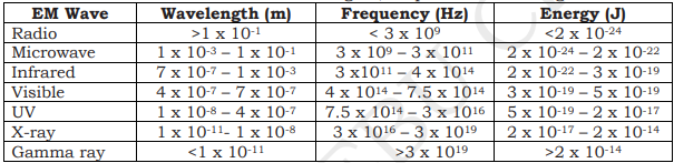
ELECTROMAGNETIC SPECTRUM
continuum of EM waves arranged according to frequency and wavelength
according to increasing frequency: radio waves, microwaves, infrared, visible light, ultraviolet, x-rays, gamma rays.
different types are defined by the amount of energy carried or possessed by the photons
waves with short wavelengths have high energy and can be very dangerous
there is no sharp dividing line between one kind of wave and the next
Photons
bundles of wave energy
energy of a photon is given by the equation:
E = hf
E = energy of a photon (Photon Energy)
h = Planck’s constant
= 6.63 x 10⁻³⁴ J/s
J = joule
f = frequency
COMMON PROPERTIES OF EM WAVES
carry energy from one place to another
do not refuse a medium to travel
they show reflection, refraction, absorption, and interference
transverse waves
GAMMA RAYS |
|---|
Wavelength: less than 0.01 nm
Frequency (Hz): more than 10 EHz
Photon Energy (eV): 100 keV - 300+ GeV
X-RAYS |
|---|
Wavelength: 0.01 - 10 nm
Frequency (Hz): 30 EHz - 30 PHz
Photon Energy (eV): 120 eV - 120 keV
ULTRAVIOLET |
|---|
Wavelength: 10 nm - 400 nm
Frequency (Hz): 30 PHz - 790 THz
Photon Energy (eV): 3eV - 124 eV
VISIBLE LIGHT |
|---|
Wavelength: 390 nm - 750 nm
Frequency (Hz): 790 THz - 405 THz
Photon Energy (eV): 1.7 eV - 3.3 eV
INFRARED |
|---|
Wavelength: 750 nm - 1 mm
Frequency (Hz): 405 THz - 300 GHz
Photon Energy (eV): 1.24 meV - 1.7 eV
MICROWAVES |
|---|
Wavelength: 1 mm - 1 meter
Frequency (Hz): 300 GHz - 300 MHz
Photon Energy (eV): 1.24 μeV - 1.24 meV
* μ = micro
RADIO WAVES |
|---|
Wavelength: 1 mm - km
Frequency (Hz): 300 GHz - 3 Hz
Photon Energy (eV): 12.4 feV - 1.24 meV
TYPES OF ELECTROMAGNETIC RADIATION
Radio
used to broadcast radio and television
Microwaves
used in cooking, radar, telephone, and other signals
Infrared
transmits heat from sun, fires, radiators
Visible Light
makes things able to be seen
Ultraviolet
absorbed by the skin, used in fluorescent tubes
X-rays
used to view inside of bodies and objects
Gamma rays
used in medicine for killing cancer cells
RADIO WAVES
have the longest wavelengths in the EM spectrum
range from the length of a football to larger than our planet
Heinrich Hertz proved the existence of radio waves in the late 1880s
used to transmit sound and picture information over long distances
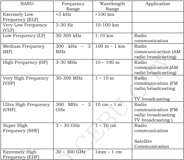
Low frequency waves are suitable for communication over great distances. But the curvature of the earth limits the range to about 80 kilometers. To extend the range, a repeater is used.
High frequency waves can be reflected by the ionosphere. This enables the waves to be transmitted over great distances.
Medium and high frequency waves are used for broadcasting by local radio stations.
CHARACTERISTICS
not line of sight
can pass through walls
longer range
not light sensitive
DISADVANTAGES
communication devices that make use of the same frequencies interfere with their transmission
easier to “eavesdrop” since signals are transmitted in a space rather than a wire
more costly than infrared
MICROWAVES
have smaller wavelengths than radio waves
used in satellite communications, radar, television transmission, and cooking.
wavelengths ranging from as long as one meter to as short as one millimeter
the prefix “micro-” in “microwave” is not meant to suggest a wavelength in the micrometer range. It indicates that microwaves are “small” because have shorter wavelengths as compared to waves used in typical radio broadcasting
APPLICATIONS
Terrestrial Communication
Satellite Communication
Microwave Oven
a part of the oven produces microwaves
the microwaves are sent to the reflecting fan
the microwaves are reflected in many directions by the fan and the walls of the microwave oven
as microwaves pass through the food, they transfer energy to the water molecules in the form of heat. this will cook the food
INFRARED
lies beyond the red end of the visible light
emitted by all objects.
the amount and wavelength of radiation depend on temperature
below 500C, an object emits only infrared radiation
above 500C, an object glows and emits both infrared and some visible light
typical television remote control uses infrared energy at a wavelength around 940 nanometers
infrared lamps heat lamps often emit both visible and infrared energy at wavelengths between 500 nm to 3000 nm in length. They can be used to heat the bathroom or keep food warm, they can also keep small animals and reptiles warm or even to keep eggs warm so they can hatch
divided into near-, mid-, and far-infrared. The region from 8 to 15 microns (µm) is referred to by Earth scientists as thermal infrared since these wavelengths are best for studying the longwave thermal energy radiating from our planet
DISCOVERY OF INFRARED
In 1800, William Herschel conducted an experiment measuring the difference in temperature between the colors in the visible spectrum. He placed thermometers within each color of the visible spectrum. The results showed an increase in temperature from blue to red. When he noticed an even warmer temperature measurement just beyond the red end of the visible spectrum, Herschel had discovered infrared light.
APPLICATIONS
Thermal Imaging
Infrared Photographs
Infrared Scanners
VISIBLE LIGHT
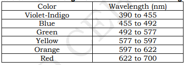
The visible light spectrum is the segment of the electromagnetic spectrum that the human eye can view. More simply, this range of wavelengths is called visible light. Typically, the human eye can detect wavelengths from 380 to 700 nanometers.
As the full spectrum of visible light travels through a prism, the wavelengths separate into the colors of the rainbow because each color is a different wavelength. Violet has the shortest wavelength, at around 380 nanometers, and red has the longest wavelength, at around 700 nanometers.
lies in between the infrared and ultraviolet rays
thinnest slice in the spectrum
only EM wave perceived by the human eye
white light, like that of the sunlight, is made up of a variety of colors arranged as follows: red, orange, yellow, green, blue, indigo, violet.
Isaac Newton's experiment in 1665 showed that a prism bends visible light and that each color refracts at a slightly different angle depending on the wavelength of the color.
do not distinguishably separate between colors but continuously changing from red-violet
EM wave can be bent when traveling from one medium to another
violet bends most
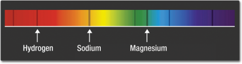
Close examination of the visible-light spectrum from our Sun and other stars reveals a pattern of dark lines—called absorption lines. These patterns can provide important scientific clues that reveal hidden properties of objects throughout the universe. Certain elements in the Sun's atmosphere absorb certain colors of light. These patterns of lines within spectra act like fingerprints for atoms and molecules. Looking at the Sun's spectrum, for example, the fingerprints for elements are clear to those knowledgeable about those patterns.
Patterns are also evident in a graph of an object's reflectance. Elements, molecules, and even cell structures have unique signatures of reflectance. A graph of an object's reflectance across a spectrum is called a spectral signature.
used as proof for CMB (Cosmic Microwave Background)
sky is blue because of chemical components in the atmosphere (nitrogen) that refracts blue light the most
sunlight emits many EM waves like UV, infrared, etc but the only visible to us is visible light
Our eyes are sensitive to electromagnetic waves of wavelengths that ranges from 4 x 10⁻⁷ m to 7 x 10⁻⁷ m.
ULTRAVIOLET
has shorter wavelengths than visible light. Although UV waves are invisible to the human eye, some insects, such as bumblebees, can see them. This is similar to how a dog can hear the sound of a whistle just outside the hearing range of humans.
wavelength shorter than that of visible light in the range 10 nm to 400 nm
Solar UV radiation is commonly subdivided into three regions: UV-A (320–400 nm), UV-B (290–320 nm), and UV-C (220–290 nm), ranked from long to shorter wavelengths (from smaller to larger energies). Most UV-B and all UV-C is absorbed by ozone (O3) molecules in the upper atmosphere. Consequently, 99% of the solar UV radiation reaching the Earth’s surface is UV-A.
There are other schemes for dividing UV into different categories, another common one is: near-ultraviolet (NUV – 300-400 nm), middle ultraviolet (MUV – 200- 300 nm), far ultraviolet (FUV – 200-122 nm), and extreme ultraviolet (EUV- 121-10 nm).
TYPES OF UV RAYS
UV-A |
|---|
tanning, wrinkles |
UV-B |
|---|
harmful rays that cause sunburn and cancerexposure to UV-B rays increases the risk of DNA and other cellular damage in living organismsabout 95% UV-B rays are absorbed by ozone in the earth’s atmosphere |
UV-C |
|---|
most harmfulalmost completely absorbed by our atmospheresterilization |
SPF 15 and above for sun protection
ultraviolet rays can damage tissue, burn the skin and damage the eyes
Scientists studying astronomical objects commonly refer to different subdivisions of ultraviolet radiation:
near ultraviolet (NUV)
middle ultraviolet (MUV)
far ultraviolet (FUV)
extreme ultraviolet (EUV)
USES
production of vitamin D in our skin
sterilization of water in drinking fountains
identifying original from fake banknotes
used to sterilize medical equipment
dental tools
sunbed
DISCOVERY OF ULTRAVIOLET
In 1801, Johann Ritter conducted an experiment to investigate the existence of energy beyond the violet end of the visible spectrum. Knowing that photographic paper would turn black more rapidly in blue light than in red light, he exposed the paper to light beyond violet. Sure enough, the paper turned black, proving the existence of ultraviolet light.
X-RAYS
have much higher energy and much shorter wavelengths than ultraviolet light, and scientists usually refer to x-rays in terms of their energy rather than their wavelength. This is partially because x-rays have very small wavelengths, between 0.03 and 3 nanometers, so small that some x-rays are no bigger than a single atom of many elements.
Our Sun's radiation peaks in the visual range, but the Sun's corona is much hotter and radiates mostly x-rays. To study the corona, scientists use data collected by x-ray detectors on satellites in orbit around the Earth. Japan's Hinode spacecraft produced these x-ray images of the Sun that allow scientists to see and record the energy flows within the corona.
X-rays are electromagnetic waves with wavelengths in the range of 0.01 to 10 nanometers, corresponding to frequencies in the range 3×10¹⁶ Hz to 3×10¹⁹ Hz. X-rays come just after the ultraviolet rays. They are of shorter wavelengths but carry higher energy than the ultraviolet. They are produced using an X-ray tube. They are emitted when fast moving electrons hit a metal target.
Long wavelength X-rays can penetrate the flesh but not the bones. They are used in X-ray photographs to help doctors look inside the body. They are useful in diagnosing bone fractures and tumors.
Short wavelength X-rays can penetrate even through metals. They are used in industry to inspect welded joints for faults.
All X-rays are dangerous because they can damage healthy living cells of the body. This is the reason why frequent exposure to X-rays should be avoided. Too much exposure to X-rays can damage body tissues and can cause cancer.
DISCOVERY OF X-RAYS
X-rays were first observed and documented in 1895 by German scientist Wilhelm Conrad Roentgen. He discovered that firing streams of x-rays through arms and hands created detailed images of the bones inside. When you get an x-ray taken, x-ray sensitive film is put on one side of your body, and x-rays are shot through you. Because bones are dense and absorb more x-rays than skin does, shadows of the bones are left on the x-ray film while the skin appears transparent.
first clinical x-ray taken by Wilhelm Roentgen on December 22, 1895, of his wife’s hand, showing wedding ring and bones of fingers
15 minute exposure (his wife)
USES
medical imaging
security
radiation therapy
checking authenticity of art pieces
engineering applications
industries
research and development
astronomy
GAMMA RAYS
lie at the other end of the electromagnetic spectrum
shortest in wavelength and highest in frequency
carry the highest amount of energy, thus, they are more dangerous.
emitted by stars and some radioactive substances.
can only be blocked with lead and thick concrete.
ionizing radiation and are thus biologically hazardous.
classically produced by the decay from high energy states of atomic nuclei, a process called gamma decay, but are also created by other processes.
PAUL VILLARD |
|---|
a French chemist and physicist, discovered gamma radiation in 1900, while studying radiation emitted from radium during its gamma decay. Villard’s radiation was named “gamma rays” by Ernest Rutherford in 1903. |
have the smallest wavelengths and the most energy of any wave in the electromagnetic spectrum
produced by the hottest and most energetic objects in the universe, such as neutron stars and pulsars, supernova explosions, and regions around black holes.
On Earth, gamma waves are generated by nuclear explosions, lightning, and the less dramatic activity of radioactive decay.
COBALT-60 (CO-60) |
|---|
used medically for radiotherapy. it is used to treat cancer. |
USES
used to treat cancer (radiotherapy)
used in sterilizing medical equipment
nuclear industry
MAGNETISM AND MAGNETIC FORCES
1. Magnetic Fields
Poles of a Magnet
A magnet can exert a force on another nearby magnet. Magnets have two poles:
A north pole
A south pole
A magnetic force is strongest near a magnet’s poles.
The Rules of Magnetism
Two magnets will either attract or repel each other in the following way:
Like poles (N-N or S-S) repel
Unlike poles (N-S or S-N) attract
Magnetic forces are non-contact forces–this means that magnets affect each other without touching.
Induced and Permanent Magnetism
Iron, steel, nickel and cobalt are magnetic materials. They are affected by magnets and are attracted to either pole of a magnet.
Permanent Magnets
A permanent magnet is often made from a magnetic material such as iron. A permanent magnet always causes a force on other magnets, or on magnetic materials.
Key features of a permanent magnet:
It produces its own magnetic field
The magnetic field cannot be turned on and off – it is there all the time
Bar magnets and horseshoe magnets are examples of permanent magnets.
Induced Magnets
Unlike a permanent magnet, an induced magnet only becomes a magnet when it is placed in a magnetic field. The induced magnetism is quickly lost when the magnet is removed from the magnetic field.
The iron filings in the image become induced magnets when they are near the bar magnet. Like all induced magnets:
They are only attracted by other magnets, they are not repelled
They lose most or all of their magnetism when they are removed from the magnetic field
Testing for Magnetism
A permanent magnet can:
Attract or repel another permanent magnet
Attract a magnetic material (but not repel it)
This means that you can only show that an object is a permanent magnet by checking if it repels another magnet.
Magnetic Fields
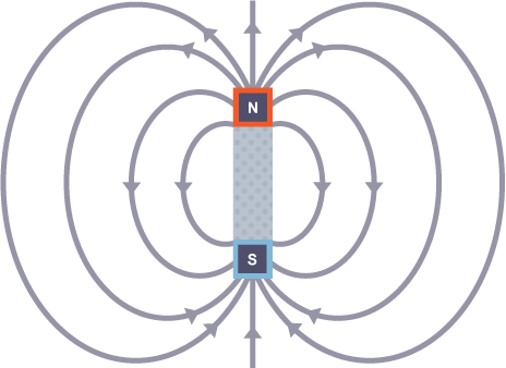
A magnetic field is the region around a magnet where a force acts on another magnet or on a magnetic material.
Detecting Magnetic Fields
A magnetic field is invisible, but it can be detected using a magnetic compass. A compass contains a small bar magnet on a pivot so that it can rotate. The compass needle points in the direction of the Earth’s magnetic field, or the magnetic field of a magnet.
Magnetic fields can be mapped out using small plotting compasses:
Place the plotting compass near the magnet on a piece of paper
Mark the direction the compass needle points
Move the plotting compass to many different positions in the magnetic field, marking the needle direction each time
Join the points to show the field lines
The needle of a plotting compass points to the south pole of the magnet.
The behavior of a compass shows that the Earth has a magnetic field. Scientists believe that this field is produced by convection currents in the Earth’s core, which is made from iron and nickel. When a plotting compass is placed in the Earth’s magnetic field, the north pole of the compass will line up with the Earth’s magnetic field lines and point to magnetic south.
Drawing a Magnetic Field
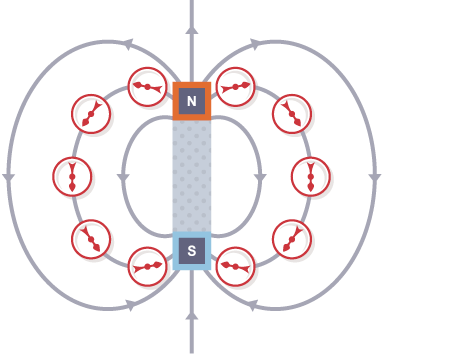
The diagram shows the magnetic field around a bar magnet.
The diagram shows these key features:
The magnetic field lines never cross each other
The closer the lines, the stronger the magnetic field
The lines have arrowheads to show the direction of the force exerted by a magnetic north pole
The arrowheads point from the north pole of the magnet to its south pole
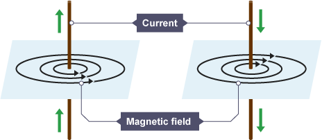
Magnetic Fields in a Wire
When a current flows in a wire, it creates a circular magnetic field around the wire. This magnetic field can deflect the needle of a magnetic compass. The strength of the magnetic field is greater:
Closer to the wire
If the current is increased
Solenoids
A solenoid consists of a wire coiled up into a spiral shape. When an electric current flows, the shape of the magnetic field is very similar to the field of a bar magnet. The field inside a solenoid is strong and uniform. The small magnetic fields caused by the current in each coil add together to make a stronger overall magnetic field.
2. Uses of Magnetism
The Motor Effect
A wire carrying a current creates a magnetic field. This can interact with another magnetic field, causing a force that pushes the wire at right angles. This is called the motor effect.
The current is traveling along the wire and the magnetic field from the permanent magnet goes from left to right. The field from the permanent magnet and the field due to the current in the wire combine and there is a force on the wire. The current, the magnetic field and the force are all at right angles to one another.
If the current and the magnetic field are parallel to each other (i.e. they are in the same direction) they cancel each other out, and no force is generated. This is because the wire is not passing through any magnetic field lines.
Fleming’s Left-hand Rule
The force on a given length of wire in a magnetic field increases when:
The current in the wire increases
The strength of the magnetic field increases
For any given combination of current and magnetic field strength, the force is greatest when the direction of the current is 90° to the direction of the magnetic field. There is no motor effect force if the current and magnetic field are parallel to each other.
The direction of the force can be found using Fleming’s left-hand rule.
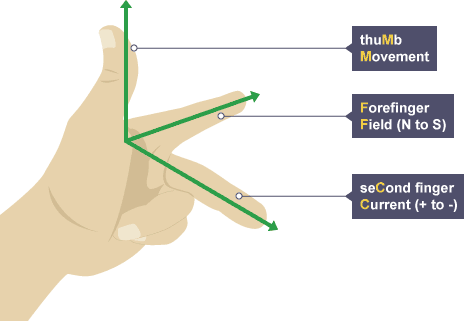
Hold your thumb, forefinger and second finger at right angles to each other:
The thumb shows the direction of the motor effect force on the conductor carrying the current
The forefinger is lined up with magnetic field lines pointing from north to south
The second finger is lined up with the current pointing from positive to negative
Calculating Electric Force
To calculate the force on a wire carrying a current at right angles to a magnetic field, use the equation:
Force on a conductor (at right angles to a magnetic field) carrying a current = magnetic flux density × current × length
This is when:
Force is measured in newtons (N)
Magnetic flux density (magnetic field strength) is measured in tesla (T)
Current is measured in amps (A)
Length is measured in meters (m)
Example:
2 A flows through a 50 cm wire. Calculate the force acting on the wire when it is placed at right angles in a 0.4 T magnetic field.
First convert the units:
50 cm = 50 ÷ 100 = 0.5 m
Then substitute the values into the equation:
force on a conductor carrying a current = magnetic flux density × current × length
force = 0.4 × 2 × 0.5
force = 0.4 N
Electric Motors
A coil of wire carrying a current in a magnetic field experiences a force that tends to make it rotate. This effect can be used to make an electric motor.
The diagram shows a simple motor using direct current (dc).
Starting from the position shown in the diagram of the dc motor:
Current in the left hand part of the coil causes a downward force, and current in the right hand part of the coil causes an upward force
The coil rotates anti-clockwise because of the forces described above
When the coil is vertical, it moves parallel to the magnetic field, producing no force. This would tend to make the motor come to a stop, but two features allow the coil to continue rotating:
The momentum of the motor carries it on round a little
A split ring commutator changes the current direction every half turn
Once the conducting brushes reconnect with the commutator after a half turn:
Current flows in the opposite direction through the wire in the coil
Each side of the coil is now near the opposite magnetic pole
This means that the motor effect forces continue to cause anti-clockwise rotation of the coil.
Loudspeakers
The motor effect is used in loudspeakers. In these devices, variations in an electric current cause variations in the magnetic field produced by an electromagnet. This causes a cone to move, which creates pressure variations in the air and forms sound waves.
Alternating current (ac) supplied to the loudspeaker creates sound waves in the following way:
A current in the coil creates an electromagnetic field
The electromagnetic field interacts with the permanent magnet, generating a force which pushes the cone outwards
The current is made to flow in the opposite direction
The direction of the electromagnetic field reverses
The force on the cone now pulls it back in
Repeatedly alternating the current direction makes the cone vibrate in and out
The cone vibrations cause pressure variations in the air, which are sound waves
To make a loudspeaker cone vibrate correctly, the electric current must vary in the same way as the desired sound. Headphones contain small loudspeakers.
3. Electromagnetic Induction
Potential Difference
A potential difference or voltage is needed to make an electric current flow in a circuit.
Inducing a Potential Difference
A potential difference can be induced (created) in a conductor when there is movement between the conductor and a magnetic field. This can occur in two different ways:
a coil of wire is moved in a magnetic field
a magnet is moved into a coil of wire
This is called electromagnetic induction and is often referred to as the generator effect.
The induced voltage produces an induced current if the conductor is connected in a complete circuit. As with all currents, the induced current creates a magnetic field around itself.
It is important to remember that if a magnet is moved into a coil of wire, the induced magnetic field tends to repel the magnet back out of the coil. This effect occurs whether a magnet is moved into a coil, or a coil is moved around a magnet.
Factors Affecting the Induced Potential
The direction of the induced potential difference or induced current depends on the direction of movement. The current is reversed when:
The magnet is moved out of the coil
The other pole of the magnet is moved into the coil
An induced potential difference or induced current will increase if:
The speed of movement is increased
The magnetic field strength is increased
The number of turns on the coil is increased
Alternators
An alternating current (ac) generator is a device that produces a potential difference. A simple AC generator consists of a coil of wire rotating in a magnetic field. Cars use a type of AC generator, called an alternator, to keep the battery charged and to run the electrical system while the engine is working.
As one side of the coil moves up through the magnetic field, a potential difference is induced (created) in one direction. As the rotation continues and that side of the coil moves down, the induced potential difference reverses direction. This means that the alternator produces a current that is constantly changing. This is alternating current or ac.
Alternator Output on a Graph
The output of an alternator can be represented on a potential difference–time graph with potential difference on the vertical axis and time on the horizontal axis.
The maximum potential difference or current can be increased by:
Increasing the rate of rotation
Increasing the strength of the magnetic field
Increasing the number of turns on the coil
Dynamos
A direct current (dc) generator is another device that produces a potential difference. A simple dc generator consists of a coil of wire rotating in a magnetic field. However, it uses a split ring commutator rather than the two slip rings found in alternating current (ac) generators. Some bike lights use a type of dc generator called a dynamo to run the lamps while the wheels are turning.
In a dynamo, a split ring commutator changes the coil connections every half turn. As the induced potential difference is about to change direction, the connections are reversed. This means that the current to the external circuit always flows in the same direction.
Dynamo Output on a Graph
The output of a dynamo can be shown on a potential difference–time graph. The graph shows a sine curve that stays in the same direction all the time. The maximum potential difference or current can be increased by:
Increasing the rate of rotation
Increasing the strength of the magnetic field
Increasing the number of turns on the coil
Microphones
The microphone is a device that converts sound waves into electrical signals. Microphones use the generator effect to induce (create) a changing current from the pressure variations of sound waves.
Moving-coil Microphones
In a moving-coil microphone:
Pressure variations in sound waves cause the flexible diaphragm to vibrate
The vibrations of the diaphragm cause vibrations in the coil
The coil moves relative to a permanent magnet, so a potential difference is induced in the coil
The coil is part of a complete circuit, so the induced potential difference causes a current to flow around the circuit
The changing size and direction of the induced current matches the vibrations of the coil
The electrical signals generated match the pressure variations in the sound waves
4. Transformers
What is a Transformer?
A transformer is a device that can change the potential difference or voltage of an alternating current (ac):
A step-up transformer increases the potential difference
A step-down transformer reduces the potential difference
Structure of a Transformer
A basic transformer is made from two coils of wire; a primary coil from the ac input and a secondary coil leading to the ac output. The coils are not electrically connected. Instead, they are wound around an iron core. This is easily magnetized and can carry magnetic fields from the primary coil to the secondary coil.
When a transformer is working:
A primary potential difference drives an alternating current through the primary coil
The primary coil current produces a magnetic field, which changes as the current changes
The iron core increases the strength of the magnetic field
The changing magnetic field induces a changing potential difference (voltage) in the secondary coil
The induced potential difference produces an alternating current in the external circuit
Potential Difference
The ratio of potential differences on the transformer coils matches the ratio of the numbers of turns on the coils.
This equation can be used to calculate what the output might be from a particular transformer, or to work out how to design a transformer to make a particular potential difference (pd) change:
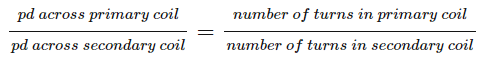
This is when:
The potential difference in the primary (input) coil is in volts (V)
The potential difference in the secondary (output) coil is in volts (V)
In a step-up transformer, the potential difference in the secondary coil is greater than the potential difference in the primary coil. In a step-down transformer, the potential difference in the primary coil is greater than the potential difference in the secondary coil.
IB PHYSICS Topic 3: Thermal Physics
3.1 Thermal Concepts
Molecular Theory of Solids, Liquids, and Gasses
Molecules are held together by intermolecular forces.
Plasma state is a highly ionized, electrically conductive gas with charged ions and free electrons; it exhibits conductivity in high-temperature environments
Temperature and Absolute Temperature
Temperatures describe an object's hotness or coldness, determining heat flow direction.
Heat transfer: higher to lower temperature; termed "heat."
Thermal equilibrium: objects share the same temperature.
Kelvin temperature is calculated by adding 273.15 to the Celsius temperature.
Absolute temperature (Kelvin) is proportional to the average kinetic energy per molecule.
Absolute zero: 0K or -273°C, particles at zero average kinetic energy.
Internal Energy
Internal energy: sum of total kinetic and potential energy.
Kinetic energy is associated with molecular motions.
Potential energy is linked to intermolecular forces.
Specific Heat Capacity
Substance-specific heat capacity: heat needed to raise 1kg by 1K.
Different substances have distinct heat capacities due to varying properties.
Thermal capacity: Q = cθ (or Q = cΔT) - or the heat to raise the object's temperature by 1K.
Heat (Q): The unit of heat is typically measured in joules (J) in the International System of Units (SI).
Thermal capacity (c): The unit of thermal capacity is also joules per Kelvin (J/K) in the SI system.
Temperature change (θ or ΔT): The unit of temperature change is Kelvin (K) in the SI system.
Phase Change
Solid to Liquid (Melting)
Kinetic energy is unchanged; potential energy increases.
Liquid to Solid (Freezing)
Kinetic energy is unchanged; potential energy decreases.
Liquid to Gas (Boiling)
Kinetic energy is unchanged; potential energy increases.
Gas to Liquid (Condensation)
Kinetic energy is unchanged; potential energy decreases.
During phase change, temperature and kinetic energy remain constant, while potential energy changes.
Specific Latent Heat
Specific latent heat: heat needed for phase change without temperature change.
Latent Heat of Fusion
Heat to change 1kg from solid to liquid.
Latent Heat of Vaporization
Heat to change 1kg from liquid to gas.
3.2 Modeling a Gas
Pressure
Pressure: normal force per unit area.
Equation: P = F/A.
Pressure (P): The unit of pressure is measured in pascals (Pa) in the International System of Units (SI). One pascal is equivalent to one newton per square meter (N/m²).
Force (F): The unit of force is measured in newtons (N) in the SI system.
Area (A): The unit of area is measured in square meters (m²) in the SI system.
Equation of State for an Ideal Gas
Ideal gas equation: PV = nRT, where R = 8.31 (J/mol/K).
Pressure (P): The unit of pressure is typically measured in pascals (Pa) in the International System of Units (SI).
Volume (V): The unit of volume is typically measured in cubic meters (m³) in the SI system.
Amount of substance (n): The unit of amount of substance is measured in moles (mol).
Gas constant (R): The unit of the gas constant depends on the units used for pressure, volume, and temperature in the equation. In this case, R = 8.31 J/mol/K, where the unit of R is joules per mole per Kelvin (J/mol/K).
Temperature (T): The unit of temperature is measured in Kelvin (K) in the SI system.
Kinetic Model of an Ideal Gas
Assumptions:
Perfectly elastic molecule collisions.
Identical spherical molecules.
Negligible molecular volume compared to gas volume.
No interaction except during collisions.
Implications:
Absolute temperature is directly proportional to average kinetic energy and speed.
Mole, Molar Mass, and Avogadro Constant
Mole:
Unit of quantity, like a “dozen.”
1 mole = 6.022*1023 atoms or molecules (Avogadro’s constant).
Molar Mass:
Mass of 1 mole of any element or compound.
Avogadro’s Constant:
6.022*1023.
Differences Between Real and Ideal Gasses
Real gasses deviate from ideal assumptions.
Intermolecular forces exist in real gasses.
Molecular volume is not negligible.
Real gasses may resemble ideal gasses under high temperatures and low pressure.
Circular Motion and Gravitation
Uniform Circular Motion
Uniform circular motion is the motion of an object moving in a circular path at a constant speed. In this type of motion, the object's velocity is constantly changing due to the change in direction of its motion. You should remember that although the speed may be constant, the velocity is not because the direction is always changing meaning that the velocity is always changing. Since the velocity is changing, there must be acceleration. The acceleration does not change the speed of the object, rather it changes the direction of the velocity to keep the object moving along the circular path.
Centripetal Force and Acceleration
Centripetal force is the force that acts on an object moving in a circular path, directed towards the center of the circle. It is responsible for keeping the object moving in a circular path. The centripetal acceleration is what turns the velocity vectors to keep the object traveling in a circle. The magnitude of the centripetal acceleration depends on the object’s speed, v, and the radius of the circular path, r,
a꜀ = v^2/r
where a꜀ is the centripetal acceleration, v is the velocity of the object, and r is the radius of the circle.
The centripetal force required to keep an object moving in a circular path is given by the formula:
F = ma = mv^2 / r
where F is the centripetal force, m is the mass of the object, v is the velocity of the object, and r is the radius of the circle.
Some examples of uniform circular motion include the motion of a car around a circular track, the motion of a satellite orbiting the Earth, and the motion of a ball on a string being swung in a circle.
Gravitational and Electric Forces
The four fundamental forces in physics are the gravitational force, the electromagnetic force, the weak force, and the strong force. Gravity dominates at the largest mass and distance scales because its effects are proportional to the mass of the objects involved.
Gravitational Force
The gravitational force is the force of attraction between two masses. It is one of the weakest forces in nature, but it dominated at large mass and distances. An example of this is our solar system where the huge gravitational pull of the sun keep the planets in orbit.
Attractive force between two objects with mass
Proportional to the product of their masses and inversely proportional to the square of the distance between them
Described by Newton's Law of Universal Gravitation: F = G (m1 m2) / r^2
G is the gravitational constant (6.674 10^-11 N m^2 / kg^2)
Electric Force
Attractive or repulsive force between two charged objects
Proportional to the product of their charges and inversely proportional to the square of the distance between them
Described by Coulomb's Law: F = k (q1 q2) / r^2
k is the Coulomb constant (9 10^9 N m^2 / C^2)
Gravitational Acceleration
Gravitational acceleration is the acceleration experienced by an object due to the force of gravity. It is denoted by the symbol 'g' and is measured in meters per second squared (m/s^2). The gravitational force is always acting vertically downward towards the center of a planet. If this is the only force that is being exerted on an object at a specific time, then the object is considered to be in free fall.
Formula
The formula for gravitational acceleration is:
g = G * M / r^2
where:
G is the gravitational constant (6.674 10^-11 N m^2 / kg^2)
M is the mass of the object causing the gravitational force
r is the distance between the object and the center of mass of the other object
On Earth, the value of gravitational acceleration is approximately 9.81 m/s^2. This means that an object in free fall near the surface of the Earth will accelerate at a rate of 9.81 m/s^2. The variable g, or the gravitational field is subject to change based on the planet itself or the object’s location relative to the planet’s surface. On Earth, we know g as 9.8 m/s^2, but on other planets, the value is different.
F₉ = m1a
Gm1m2/r^2 = m1a

a = gm/r^2
g = Gm/r^2
Electricity
CURRENT RESISTANCE AND POTENTIAL DIFFERENCE
Current and Charge
Current is the flow of electrons around a circuit AND the flow of charge in a circuit
Current is measured in amperes/amps (A).
For charge to flow, a switch must be closed to create a closed circuit.
Electrical charge can be found by using the equation Q(C) = I(A) x T(s)
Current Potential difference and resistance
Resistance is known as the opposition to current, so the higher the resistance, the lower the current.
Additionally potential difference also affects the current, so the higher the potential difference the higher the current.
Resistance can be found using this equation : R(Ω) = I (A) x V (V)
Investigating Resistance
dependant variable = Resistance
independant variable = length of wire
control variable = material of wire
Method:
Set up the apparatus by connecting two crocodile clips to the thin resistance wire a distance of 10 cm apart and setting the power supply to 1.5 V
Connect the wire, using the clips, to the rest of the circuit
Record the potential difference from the voltmeter and current from the ammeter
Using r = v/i calculate resistance
Move the clips in 10 cm intervals further apart and repeat steps 1-4
Take new measurements from the voltmeter and ammeter for each length reading
Continue until the crocodile clips are a length of 1 m apart
Using these results draw a graph of potential difference and current
sources errors in this practical:
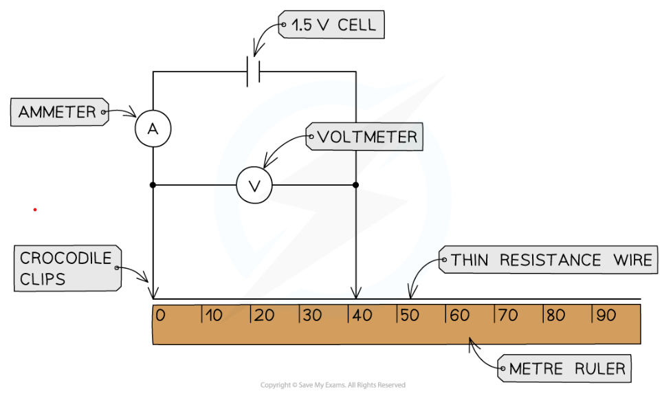
Temperature affects resistance, so when the wire heats up, the increased temperature affects the resistance as well as the length of the wire, thus affecting the results. (confounding variable) This could also be a hazard as this could cause burns so :
Only have the circuit connected to take the reading and then disconnect it straight away until you are ready to take the next reading. wait until the wire had cooled back to room temperature before taking the next reading. Use a low potential difference which will keep the current low reducing heating in the wire
zero error
subtract zero error from all readings, change equipment, attach crocodile clip directly onto where the wire is at zero.
IV Characteristics
Ohm's Law states that the current through a conductor is directly proportional to the potential difference across it
Conductors that follow this rule are known as ohmic conductors
Some examples include fixed resistors, wires and heating elements
this can be seen through this graph:

However this is only true if temperature remains constant.
Required practical : Investigating IV characteristic
Set up the circuit as shown with the fixed resistor
Vary the voltage across the component by changing the resistance of the variable resistor, using a wide range of voltages (between 8-10 readings). Check the appropriate voltage reading on the voltmeter
For each voltage, record the value of the current from the ammeter 3 times and calculate the average current
Increase the voltage further in steps of 0.5 V and repeat steps 2 and 3
Make sure to switch off the circuit in between readings to prevent heating of the component and wires
Reverse the terminals of the power supply and take readings for the negative voltage (and therefore negative current)
Replace the fixed resistor with the filament lamp, then the diode, repeating the experiment for each
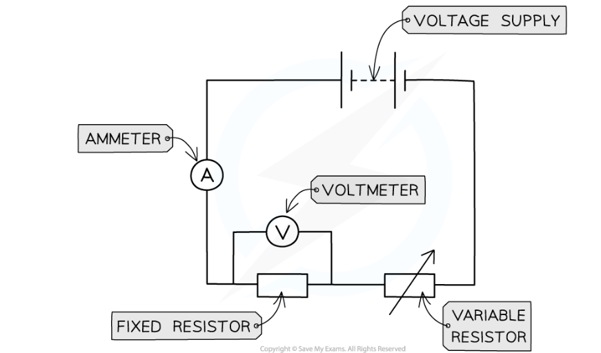
It is easy to change voltage when voltage supply is from a power pack, but if voltage supply is from a cell or battery with a fixed charge one should use a variable resistor to change its voltage
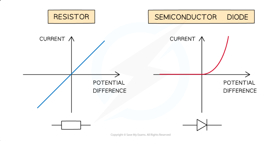
The diode is a semi conductor so it only allows the current to pass through one direction thus has very high resistance in the reverse direction.
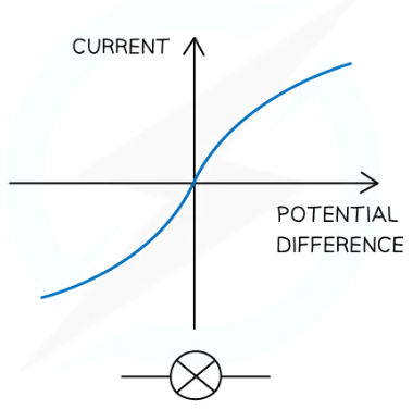
This is because the resistance of the filament lamp increases as the temperature of the filament increases
Thermistors and LDRs
A thermistor is a temperature based resistor, meaning its resistance decreases as the temperature increases vice versa.
Thus a thermistor is a temperature sensor and is regularly used as a thermostat which automatically regulates or activates a device when temperature reaches a certain point.
This means it can be used in ovens, refridgerators, fire alarms, digital thermometers and boilers
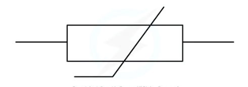
An LDR is a light-dependant resistor, as the light intensity increases the resistance decreases
An LDR is a light sensor
This means it automatically regulates the amount of light intensity on it or activates a device when the light intensity reaches above or below a certain point
examples include Lights that switch on when it gets dark (eg. garden lights, street lights),Burglar alarm circuits
useful because it is automatic not needing any human time and intervention to function correctly everyday
SERIES AND PARALLEL CIRCUITS
Series and parallel circuits
Series
Has no branches so current can only move around in one direction
Current anywhere in the circuit is the same
Voltage is shared between components
the total resistance of two components is the sum of the resistance of each component
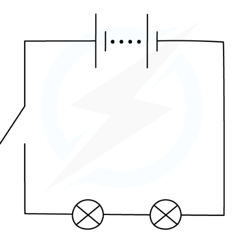
Parallel
Has 2 or more branches so some current moves through both of the branches
the total current through the whole circuit is the sum of the currents through the separate components
The potential difference across each component is the same
The total resistance of two resistors is less than the resistance of the smallest individual resistor
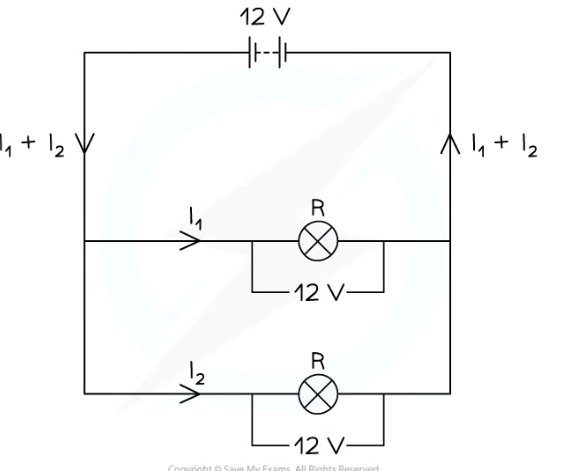
DOMESTIC USES AND SAFETY
DC is a current that is steady, constantly flowing in the same direction in a circuit, from positive to negative
DC is usally found in electric cells, or batteries, the potential difference across a cell in a d.c. circuit is in one direction only
A d.c. power supply has a fixed positive terminal and a fixed negative terminal.
AC is a current that continuously changes its direction, going back and forth around a circuit
An a.c. power supply has two identical terminals
Produced by electrical generators i.e mains electricity
Mains Electricity
In the UK, mains electricity is an alternating current with a frequency of 50 Hz and a potential difference of around 230 V
In the UK, most electrical appliances are connected to the mains using a three-core cable consisting of a live wire, a neutral wire, an Earth wire, which are made up of copper because it is a good conductor but the coating of the wires is made out of plastic because itdoesnt conduct electricity so the wires dont touch.
The live wire - brown - Carries the alternating potential difference from the mains supply to a circuit (230v)
It is the most dangerous of the three wires, because evne if the switch is open, the first part of the live wire still has 230V
If it touches the appliance without the Earth wire, it can cause electrocution
The neutral wire - blue - Forms the opposite end of the circuit to the live wire to complete the circuit, Because of its lower voltage, it is much less dangerous than the live wire
The earth wire - green yellow stripes- Acts as a safety wire to stop the appliance from becoming live by providing a low resistance path into the earth, causing a high surge in current causing the fuse to melt and breakthe cicuit
This cuts off the supply of electricity to the appliance, making it safe to touch
This prevents electric shocks from occurring if the appliance malfunctions or the live wire breaks off and touches the case of the plug
Additionally electricians also turn off the mains supply to the house when thwyh are working with live wires because their pot. idff is 0V while the live wire has pott diff of 230 which could cause a current to pass through the person into the earth causing a lethal shock, even if the device is switched off
AC and DC
DC is a current that is steady, constantly flowing in the same direction in a circuit, from positive to negative
DC is usally found in electric cells, or batteries, the potential difference across a cell in a d.c. circuit is in one direction only
A d.c. power supply has a fixed positive terminal and a fixed negative terminal.
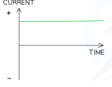
AC is a current that continuously changes its direction, going back and forth around a circuit
An a.c. power supply has two identical terminals
Produced by electrical generators i.e mains electricity
Mains Electricity..
In the UK, mains electricity is an alternating current with a frequency of 50 Hz and a potential difference of around 230 V
In the UK, most electrical appliances are connected to the mains using a three-core cable consisting of a live wire, a neutral wire, an Earth wire, which are made up of copper because it is a good conductor but the coating of the wires is made out of plastic because itdoesnt conduct electricity so the wires dont touch.
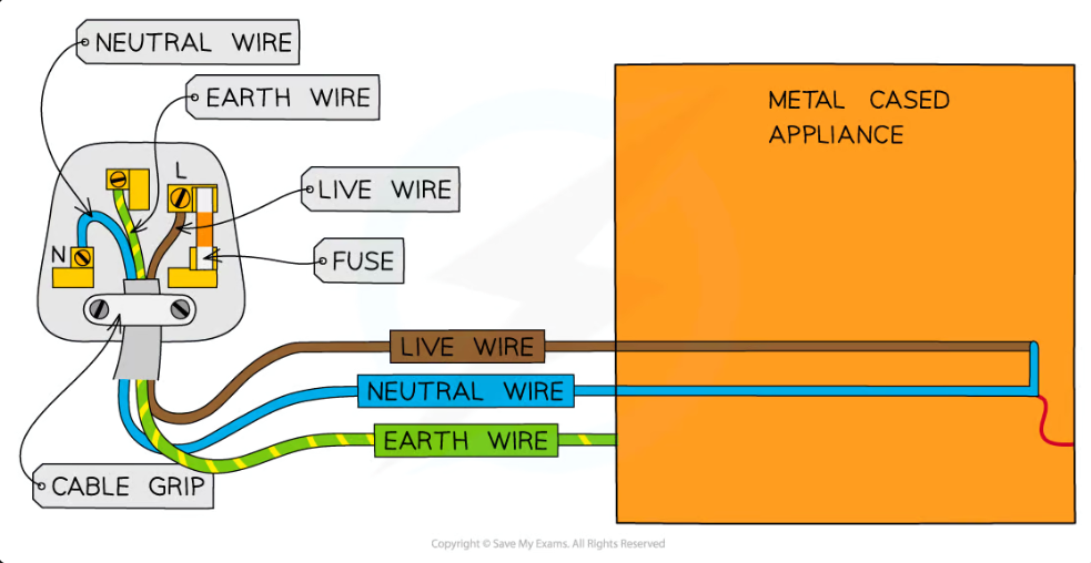
The live wire - brown - Carries the alternating potential difference from the mains supply to a circuit (230v)
It is the most dangerous of the three wires, because evne if the switch is open, the first part of the live wire still has 230V
If it touches the appliance without the Earth wire, it can cause electrocution
The neutral wire - blue - Forms the opposite end of the circuit to the live wire to complete the circuit, Because of its lower voltage, it is much less dangerous than the live wire
The earth wire - green yellow stripes- Acts as a safety wire to stop the appliance from becoming live by providing a low resistance path into the earth, causing a high surge in current causing the fuse to melt and breakthe cicuit
This cuts off the supply of electricity to the appliance, making it safe to touch
This prevents electric shocks from occurring if the appliance malfunctions or the live wire breaks off and touches the case of the plug
Additionally electricians also turn off the mains supply to the house when thwyh are working with live wires because their pot. idff is 0V while the live wire has pott diff of 230 which could cause a current to pass through the person into the earth causing a lethal shock, even if the device is switched off
ENERGY TRANSFERS
Power
BUT power is also dependant on voltage and current represesnted by the equation
P (W) = I (A) x V (V).
Due to the fact that resistance also affects voltage, the equation V= IR can be rearranged to become P (W) = I² (A) x R (Ω)
Energy Transfers
The amount of energy transferred to and from an appliance depends on:
The time the appliance is switched on for
The power of the appliance
This can be represented by the equation E (J) = P(W) x T (s)
Additionally potential difference and charge are also factors affecting energy, represented by the equation E (J) = Q (C) x V (V)
Power Ratings
Every electrical appliance has a power rating which tells you how much energy it needs to work
The power rating for domestic electrical appliances is normally given on a label. This will include:
The potential difference required to make the device work (eg. 230 V in the UK)
The frequency of the supply (eg. 50 Hz in the UK)
The power rating in Watts (this varies for each device)
The higher the power rating, the faster the energy is transferred
National grid
System of cables and transformers linking power stations to consumers (houses, factories and buildings)
a main problem of transferring energy over long distances is that it is lost very easly this is why transformers have to be used
Step up transformers are used to increase voltage because less energy is lost when there is a higher voltage
however the voltage is too high so a step down transformer is used to lower voltage to 230 v so it can be passed into homes safely
Static Electricity
This is the electricity caused by the movement of charge in a circuit in conductors
one example of this is a balloon and a wall:
1) Rubbing a balloon on a woollen jumper transfers electrons onto the balloon by friction
2) The balloon becomes negatively charged and the jumper becomes positively charged
3) The wall is uncharged initially, but when the balloon is placed near the wall, the electrons on the balloon's surface repel the electrons on the wall's surface
4) Furthermore, the positive charges on the wall's surface are attracted to the negatively charged balloon which allows the it to stick to the wall
Sparking
A spark occurs between two objects when
There is a large potential difference between the two objects
Which causes a current to flow between them
Caused by a build up of charge
Electrical Fields
A charged object creates an electric field around itself
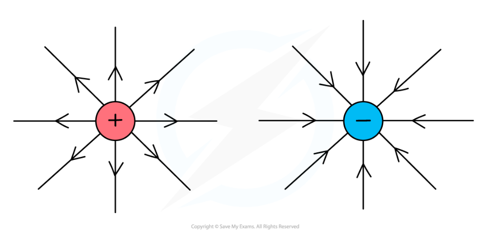
The force becomes:
Stronger as the distance between the two charged objects decreases
Simple Harmonic Motion
Simple Harmonic Motion
Simple Harmonic Motion (SHM) is a type of periodic motion where the restoring force is directly proportional to the displacement from the equilibrium position and is drected towards it.
The motion is periodic and repetitive.
The acceleration is directly proportional to the displacement and is always directed towards the equilibrium position.
The velocity is maximum at the equilibrium position and minimum at the extreme positions.
The displacement, velocity, and acceleration are all sinusoidal functions of time.
The period of oscillation is independent of the amplitude.
Examples of SHM include: A mass attached to a spring and oscillating vertically or a A pendulum swinging back and forth.
Displacement: x = A cos(ωt + φ)

Velocity: v = -Aω sin(ωt + φ)

Acceleration: a = -Aω^2 cos(ωt + φ)
where A is the amplitude, ω is the angular frequency, t is the time, and φ is the phase angle.
Energy in SHM
The total mechanical energy of a system undergoing SHM is constant and is the sum of kinetic and potential energy.
Total energy: E = 1/2 kA^2
Kinetic energy: K = 1/2 mv^2
Potential energy: U = 1/2 kx^2
where k is the spring constant, m is the mass, v is the velocity, and x is the displacement.
Force and Amplitude
Force in Simple Harmonic Motion
Since the block is acceleration and deceleration, there must be some force that is making it do so. This this cause, the spring exerts a force on the block.
It is a vector quantity, meaning it has both magnitude and direction.
The SI unit of force is Newton (N).
Force can cause an object to accelerate, change direction, or deform.
F = -kx
Also known as Hooke’s Law, the k is the called the spring constant and tells us how strong the spring is. The greater the K, the stiffer the spring actually is.
Amplitude
Amplitude is a measure of the magnitude of a wave.
It is the maximum displacement of a particle from its equilibrium position in a wave.
Amplitude is measured in meters (m) for a mechanical wave and in volts (V) for an electromagnetic wave.
The amplitude of a wave determines its intensity and energy.
The amplitude of a wave can also affedct th eforc e.
Period and Frequency
Period
The period of a wave is the time it takes for one complete cycle of the wave to occur.
It is denoted by the symbol T and is measured in seconds (s).
The period is inversely proportional to the frequency of the wave.
Mathematically, T = 1/f, where f is the frequency of the wave.
Frequency
The frequency of a wave is the number of complete cycles of the wave that occur in one second.
It is denoted by the symbol f and is measured in Hertz (Hz).
The frequency is directly proportional to the energy of the wave.
Mathematically, f = 1/T, where T is the period of the wave.
Pendulums
In a system, if the spring is used the period will increase with objects mass and decrease with as a greater spring constant increases. This is because a mass will resist acceleration and a large spring constant will make the spring exert more force.
Object's mass affects the period of the spring, not the pendulum
Mass can act as either inertial or gravitational
Gravitational mass accelerates due to the force of gravity between it and the Earth
All objects fall at the same rate due to gravitational mass
Inertial mass is not pushed by gravity but by external forces like the spring force
Inertial mass can accelerate at different rates depending on the force applied
Pendulums are a common topic in AP Physics Unit 7, which covers simple harmonic motion. A pendulum is a weight suspended from a pivot point that swings back and forth due to gravity. The period of a pendulum (the time it takes to complete one full swing) is determined by the length of the pendulum and the acceleration due to gravity. The equation for the period of a pendulum is T=2π√(L/g), where T is the period, L is the length of the pendulum, and g is the acceleration due to gravity. Pendulums are used in many applications, such as clocks and seismometers.
Torque and Rotational Motion
Rotational Motion
Rotational motion is the motion of an object around an axis or a fixed point. It is also known as circular motion. In rotational motion, an object rotates about an axis, which may or may not pass through the object. If we recall previously, an object’s mass measures its inertia. The greater the inertia on an object, the harder it is to change its velocity which means the greater the inertia, greater the force to move an object.
Linear Kinematics | Rotational Kinematics |
|---|---|
Force | Torque |
Mass | Moment of Inertia |
Acceleration | Angular Acceleration |
Fnet = ma | Tnet = Ia |
Velocity | Angular Velocity |
Angular displacement: The angle through which an object rotates.
Angular velocity: The rate of change of angular displacement with respect to time.
Angular acceleration: The rate of change of angular velocity with respect to time.
Moment of inertia: The resistance of an object to rotational motion.
Torque: The force that causes an object to rotate about an axis.
Rotational motion is important in many areas of physics and engineering, including: Mechanics, Astronomy and Robotics
Rotational Kinematics
Rotational kinematics is the study of motion of objects that rotate around a fixed axis. Like linear equations, we use rotational equations to determine the same factors. The formulas just differ slightly but are essentially the same concept with different variables and used in different ways.
Angular Displacement
Angular displacement is the change in the angle of rotation of an object. It is measured in radians and is denoted by the symbol "theta" (θ). The formula for angular displacement is:
θ = (s / r)
where s is the arc length and r is the radius of the circle.
Angular Velocity
Angular velocity is the rate of change of angular displacement. It is measured in radians per second and is denoted by the symbol "omega" (ω). The formula for angular velocity is:
ω = (θ / t)
where t is the time taken for the angular displacement.
Angular Acceleration
Angular acceleration is the rate of change of angular velocity. It is measured in radians per second squared and is denoted by the symbol "alpha" (α). The formula for angular acceleration is:
α = (ωf - ωi) / t
where ωf is the final angular velocity, ωi is the initial angular velocity, and t is the time taken for the change in angular velocity.
Relationship between Linear and Angular Motion
There is a relationship between linear and angular motion. The linear velocity of a point on a rotating object is equal to the product of the angular velocity and the radius of the circle. The formula for linear velocity is:
v = rω
Similarly, the linear acceleration of a point on a rotating object is equal to the product of the angular acceleration and the radius of the circle. The formula for linear acceleration is:
a = rα
Center of Mass
The center of mass (COM) is the point in an object or system that moves as if all the mass were concentrated at that point. It is the average position of all the parts of the system, weighted according to their masses.
The center of mass of an object or system is always located within the object or system itself.
The center of mass of a symmetrical object is located at the geometric center of the object.
The center of mass of an object or system can be outside the object or system if the mass is distributed unevenly.
The motion of an object or system can be described as if all the mass were concentrated at the center of mass.
The center of mass of a system is conserved in the absence of external forces.
Calculating the Center of Mass
The center of mass of a system can be calculated using the following formula:
COM = (m1r1 + m2r2 + … + mn rn) / (m1 + m2 + … + mn)
where m is the mass of each part of the system and r is the distance of each part from a chosen origin.
Torque
Torque is a measure of the twisting force that causes rotation. It is a vector quantity, which means it has both magnitude and direction. The magnitude of torque is given by the product of force and the perpendicular distance from the axis of rotation to the line of action of the force.
The direction of torque is given by the right-hand rule. If the fingers of the right hand are curled in the direction of rotation, then the thumb points in the direction of torque.
Formula
The formula for torque is:
τ = r x F
where τ is the torque, r is the distance from the axis of rotation to the line of action of the force, and F is the force. The SI unit of torque is the newton-meter (N·m). In the US customary system, the unit of torque is the foot-pound (ft·lb).
Mechanical Properties of Fluid
1. Pressure
Pressure (P):
Where:
F= Force, A = AreaPressure due to a fluid column:
P=hρg
Where:
h = height of the fluid,
ρ = density of the fluid,
g = acceleration due to gravity
2. Pascal's Law
Statement:
"Pressure applied to an enclosed fluid is transmitted undiminished to every portion of the fluid and the walls of the container."Applications:
Hydraulic lift:
Where
F1,F2 are forces, and
A1,A2 are areas.
3. Viscosity
Newton's Law of Viscosity:
η=(F*L)/(A*V)
Where:
η = coefficient of viscosity,
A = area,
F = force required to maintain the flow (N)V/L = velocity gradient (rate of change of velocity with distance)
Stokes’ Law:
F=6πηrv
Where:
r = radius of the sphere,
v = velocity of the objectTerminal Velocity:
vt=2r2(ρs−ρf)g9ηv_t = \frac{2 r^2 (\rho_s - \rho_f) g}{9 \eta}vt=9η2r2(ρs−ρf)g
Where
ρs\rho_sρs = density of the sphere,
ρf\rho_fρf = density of the fluid
4. Streamline and Turbulent Flow
Equation of Continuity (Conservation of Mass):
A1v1=A2v2
Where
A = cross-sectional area,
v= velocity
5. Bernoulli’s Theorem
Energy Conservation for Fluids:
P+(1/2)ρv^2+ρgh=constant
Where:
P = pressure energy,
(1/2)ρv^2 = kinetic energy per unit volume,
ρgh = potential energy per unit volume
6. Surface Tension
Surface Energy:
Surface Energy=TΔA
Where T = surface tension,
ΔA = change in surface area
Excess Pressure:
Inside a liquid drop: ΔP=2T/r
Inside a bubble: ΔP=4T/r
Capillary Rise:
h=2Tcosθ/ρgrh
Where:
θ = angle of contact,
r = radius of the capillarySimplified Notes:
Viscosity:
It’s the measure of a fluid's resistance to flow. Honey has higher viscosity than water.Bernoulli's Principle:
Faster-moving fluids exert lower pressure (used in airplanes and chimneys).Surface Tension:
It’s the tendency of liquid surfaces to shrink into the minimum surface area (seen in soap bubbles and water droplets).Capillarity:
Liquids rise or fall in a capillary tube due to adhesion and cohesion.Streamline vs. Turbulent Flow:
Streamline: Smooth and regular flow of fluid.
Turbulent: Chaotic and irregular flow.
Kinesiology:
Anterior Position - Facing Forward Ventral
Posterior Position - Toward Back / Rear Dorsal
Superior Position - Toward Head Cranial
Inferior Position - Toward Feet Causal
Medial Position - Toward Midline of Body
Lateral Position - Toward Side of Body
Sagittal Plane - Divides body into left and right Anteroposterior Plane Movements: Flexion, Extension, Hyperextension
Frontal Plane - Divides body into Front and Back Coronal / Lateral Plane Movements: Abduction and Adduction
Transverse Plane - Divides body into upper and lower Horizontal / Axial Plane Movement: Rotation
Axial Skeleton - Skull, Vertebrae, Thorax
Appendicular Skeleton - Limbs
Long Bones - Long Shaft with articular surfaces at / near ends Major bones of arms and legs
Short Bones - almost equal length and width Bones of wrists and ankles
Flat Bones - Scapula and Sternum
Irregular Bones - Irregular in shape Vertebrae
Sesamoid Bones - Embedded in tendons Patella
Wolff’s Law - bone will form in areas of stress and resorb in areas of disuse
Osteopenia - loss of bone tissue with age
Osteoporosis - critically low bone mineral density
Fossa - depressed (concave) area on the bone (fossa + condyle of adjacent bones fit together - Joint)
Condyle - rounded (convex) spot (often near / at end) (fossa + condyle of adjacent bones fit together - joint)
Tuberosity - raised area where a ligament / tendon attaches
Synthetic joints - immovable by design Non-axial joints skull joints, teeth and jaw joints
Amphiarthrodial joints - slight degree of movement pubic symphysis, intervertebral articulations
Diathrodial joints - freely moveable synovial joints uniaxial joints, biaxial joints, multi-axial joints
Range of motion - amount of movement a joint can make within a plane without causing pain
Tendons - can withhold high forces without breaking very strong broken: can take a long time to heal - little blood flow
Ligaments - somewhat more elastic than tendons more stretch provide joint stability
Parallel muscles - fusiform, flat, triangular
Pennate muscles - tendon runs along the length of the muscle and fibers are oriented at an angle towards it
Unipennate - muscle fibers insert on 1 side
Bipennate - muscle fibers insert on both sides
Moment of force - Measure of the turning effect produced by the force around an axis F(N) x Moment Arm (m)
1st class lever - EF - EMA - O - RMA - RF Seesaw mechanical advantage: =1
2nd class lever - O - RF - EF Wheelbarrow mechanical advantage: >1 Rare in human body
3rd class lever - O - EF - RF Tweezers mechanical advantage: <1 common in human body
Nonaxial joint - no axis glide movement
Uniaxial joint - 1 axis hinge or pivot
Biaxial joint - 2 axis up and down and side to side
Triaxial joint - special to the thumb gives us grip to pick things up
Multiaxial joint - over 2 axis rotation