CAD 211 REVIEWER
CAD 211 REVIEWER
A360 - Cloud rendering in AutoCAD
AutoCAD LT – AutoCAD’s lighter, more streamlined version
CURSORBADGE system - variable enables you to control the display of cursor badges.
System Variable Monitor - lets you quickly identify changes to key system variables and then set them to your preferred values.
3DORBIT - command to navigate the attached coordination model.
Smart dimensioning - is another critical feature and it works by automatically creating appropriate dimension notes based on the type of objects you select.
Revision clouds - help draw attention to specific areas of your drawing that are changing.
Ribbon gallery - offers a fast and intuitive workflow for users.
Command preview tool - Another big time saver. Helps reduce the number of Undo commands you make by letting you evaluate the potential changes of commands such as Offset, Fillet, and Trim.
You can view, create, edit, and share AutoCAD drawings on a mobile device or web browser via the AutoCAD 360 mobile and web app.
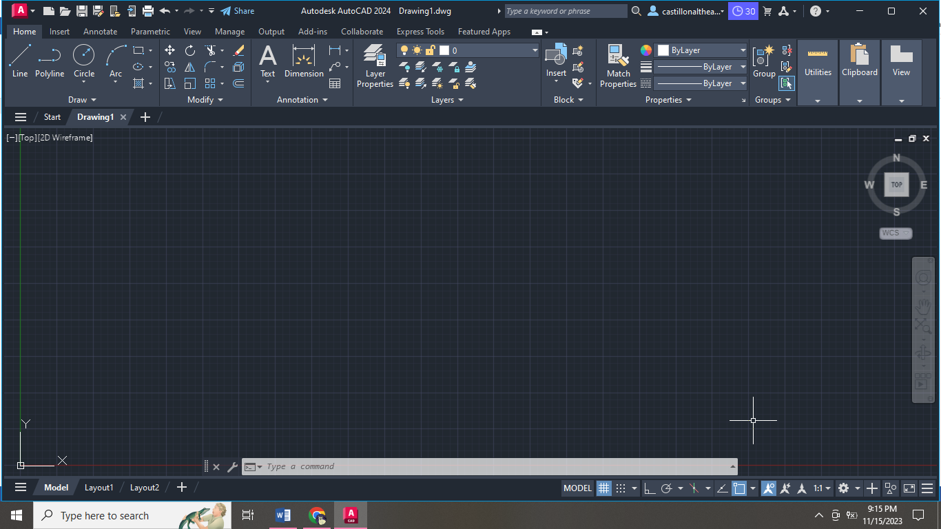
Drawing area - is where you can create and modify objects. This area allows for lots of flexibility with view cubes, navigation bars, and much more
Viewport controls - allow you to adjust both visual styles and views directly on the viewport canvas.
Navigation bar - you’ll find frequently used tools such as steering wheels, view cube, and show motion, as well as pan, zoom, and orbit.
Planar segments can now be detected in point clouds using dynamic UCS tools, allowing you to draw geometry directly on a point cloud.
The AutoCAD ribbon gallery offers a fast and intuitive workflow while the quick access toolbar lets you easily reach the tools you most commonly use
The included commands are grouped together according to types of activity, and are arranged to follow a general workflow. The following sections are covered:
Basics: This section reviews the basic AutoCAD controls.
Viewing: Pan and zoom in a drawing, and control the order of overlapping objects.
Geometry: Create basic geometric objects such as lines, circles, and hatched areas.
Precision: Ensure the precision required for your models.
Layers: Organize your drawing by assigning objects to layers.
Properties: You can assign properties such as color and linetype to individual objects, or as default properties assigned to layers.
Modifying: Perform editing operations such as erase, move, and trim on the objects in a drawing.
Blocks: Insert symbols and details into your drawings from commercial online sources or from your own designs.
Layouts: Display one or more scaled views of your design on a standard-size drawing sheet called a layout.
Notes and Labels: Create notes, labels, bubbles, and callouts. Save and restore style settings by name.
Dimensions: Create several types of dimensions and save dimension settings by name.
Printing: Output a drawing layout to a printer, a plotter, or a file. Save and restore the printer settings for each layout.
You can access nearly all the commands presented in this guide from the Home tab.
Command window - The heart of AutoCAD. It is normally docked at the bottom of the application window. The Command window displays prompts, options, and messages.
The Mouse
Most people use a mouse as their pointing device, but other devices have equivalent controls.

New Drawings
For imperial drawings that assume your units are inches, use acad.dwt or acadlt.dwt.
For metric units that assume your units are millimeters, use acadiso.dwt or acadltiso.dwt.
Units
If you plan to work in feet and inches, use the UNITS command to set the unit type to Architectural, and then when you create objects, specify their lengths in inches. If you plan to use metric units, leave the unit type set to Decimal. Changing the unit format and precision does not affect the internal precision of your drawing, it affects only how lengths, angles, and coordinates are displayed in the user interface.
Model Scale
Always create your models at full size (1:1 scale).
The term model refers to the geometry of your design.
To repeat the previous command, press Enter or the Spacebar.
To see various options, select an object and right-click or right-click a user interface element.
To cancel a command in progress or if you ever feel stuck, press Esc.
Viewing
Zoom in on a drawing to better control the order of overlapping objects.
The easiest way to change your view is by using the mouse wheel.
Zoom in or out by rolling the wheel.
Pan a view in any direction by holding the wheel down while moving your mouse.
Zoom in on a specific area for greater detail holding your mouse over the area and clicking the wheel twice.
When you zoom in or out, the location of the cursor is important. Think of your cursor as a magnifying glass.
If you cannot zoom or pan any more, type REGEN in the Command window and press Enter. This command regenerates the drawing display and resets the extents available for panning and zooming.
Overlapping Objects
If you create objects that overlap, you might need to change which objects are displayed on top or in front of the others. For example, if you want the yellow highway to cross the blue river rather than the other way around, use the DRAWORDER command to reorder the objects.
Geometry
Create basic geometric objects such as lines, circles, and hatched areas.
NOTE: If you want to simplify the display while creating geometric objects, press F12 to turn off dynamic input.
Lines
The line is the most basic and common object in AutoCAD drawings.
Alternatively, you can type LINE or just L in the Command window, and then press Enter or the Spacebar
The User Coordinate System
The user coordinate system (UCS) icon indicates the direction of the positive X and Y axis for any coordinates that you enter, and it also defines the horizontal and vertical directions in a drawing.
Grid Display
Some people like working with grid lines as a reference, while others prefer working in a blank area. To turn off the grid display, press F7. Even with the grid turned off, you can force your cursor to snap to grid increments by pressing F9.
Circles
The default option of the CIRCLE command requires you to specify a center point and a radius.
Polylines and Rectangles
A polyline is a connected sequence of line or arc segments that is created as a single object.
Use the PLINE command to create open or closed polylines
Polylines can have different starting and ending widths for each segment.
A fast way to create closed rectangular polylines is to use the RECTANG command (enter REC in the Command window).
Hatches and Fills
In AutoCAD, a hatch is a single, compound object that covers a specified area with a pattern of lines, dots, shapes, a solid fill color, or a gradient fill.
Precision
There are several precision features available, including:
Polar tracking: Snap to the closest preset angle and specify a distance along that angle. When you need to specify a point, such as when you create a line, you can use polar tracking to guide the movement of your cursor in certain directions.
Locking angles: Lock to a single, specified angle and specify a distance along that angle. If you need to draw a line at a specified angle, you can lock the angle for the next point.
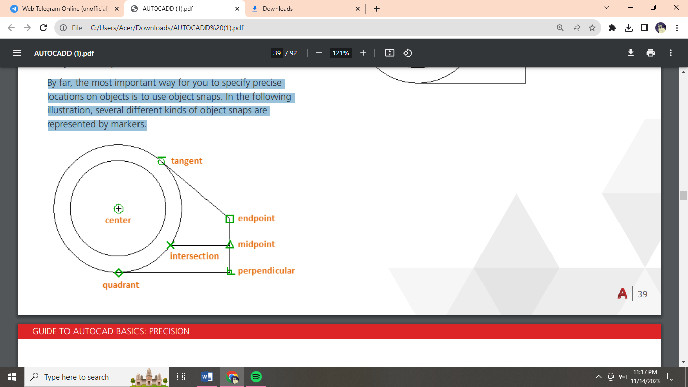
Object snaps: Snap to precise locations on existing objects, such as an endpoint of a polyline, the midpoint of a line, or the center point of a circle. By far, the most important way for you to specify precise locations on objects is to use object snaps. In the following illustration, several different kinds of object snaps are represented by markers. Set Default Object Snaps. Enter the OSNAP command to set the default object snaps, which are also called “running” object snaps.
Grid snaps: Snap to increments on a rectangular grid.
Coordinate entry: Specify a location by its Cartesian or polar coordinates, either absolute or relative.
The three most commonly used features are polar tracking, locking angles, and object snaps.
Verify Your Work
Recheck your geometry to catch mistakes early. Enter the DIST command (or just DI) to measure the distance between any two points in your model.
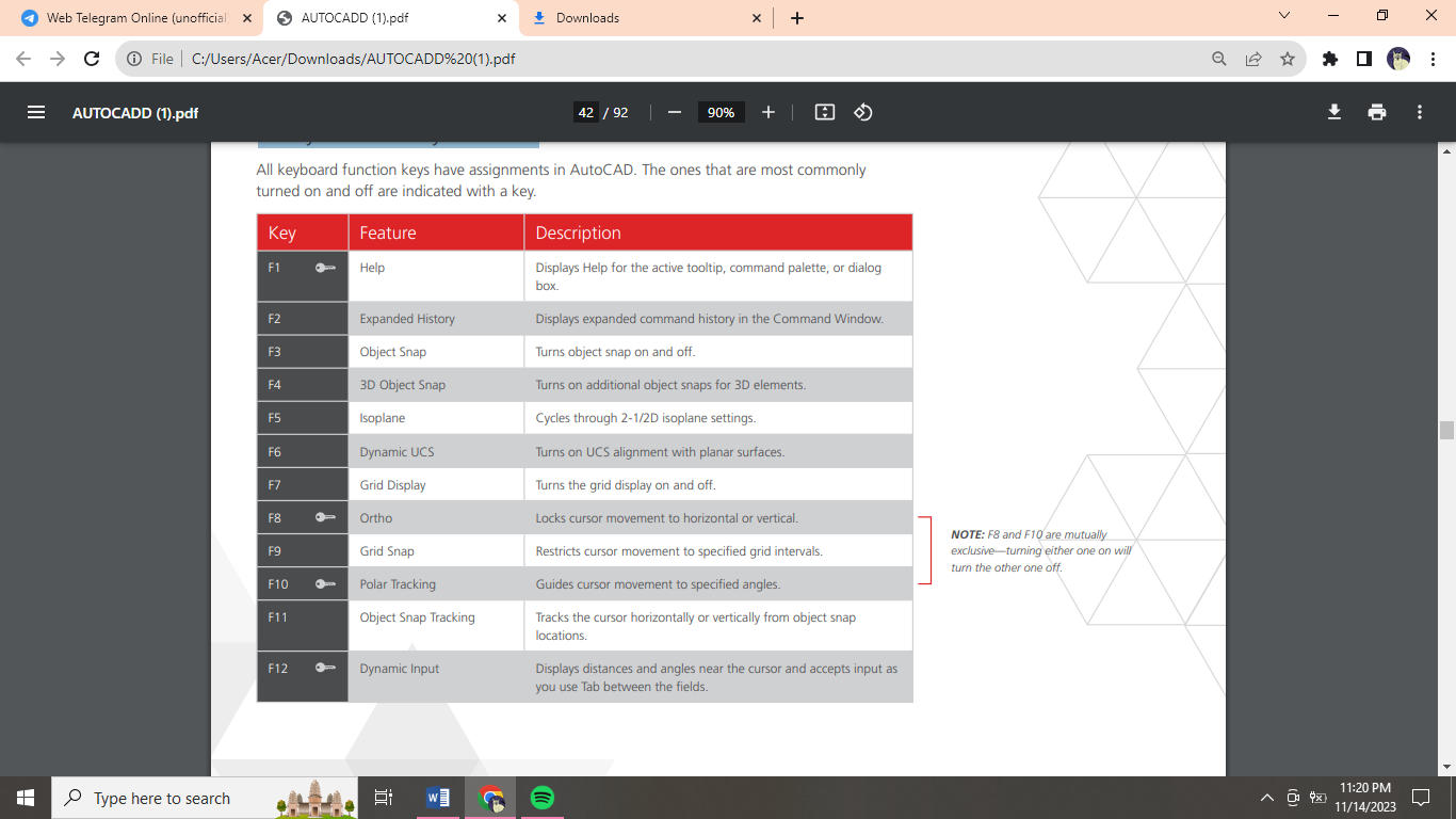 Handy Function Key Reference
Layers
Organize your drawing by assigning objects to layers.
When a drawing becomes visually complex, you can hide objects that you currently do not need to see.
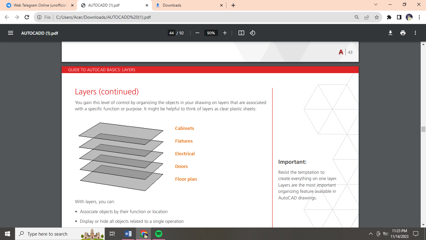 You gain this level of control by organizing the objects in your drawing on layers that are associated with a specific function or purpose. It might be helpful to think of layers as clear plastic sheets:
Resist the temptation to create everything on one layer. Layers are the most important organizing feature available in AutoCAD drawings.
Layer Controls
To see how a drawing is organized, use the LAYER command to open the Layer Properties Manager. You can either enter LAYER or LA in the Command window, or you can click the Layer Properties tool on the ribbon
Practical Recommendations:
Layer 0 is the default layer that exists in all drawings and has some esoteric properties. Instead of using this layer, it’s best to create your own layers with meaningful names.
Any drawing that contains at least one dimension object automatically includes a reserved layer named Defpoints.
Create a layer for behind-the-scenes construction geometry, reference geometry, and notes that you usually do not need to see or print.
Create a layer for layout viewports. Information about layout viewports is covered in the Layouts topic.
Create a layer for all hatches and fills. This lets you to turn them all on or off in one action.
 Layer Settings
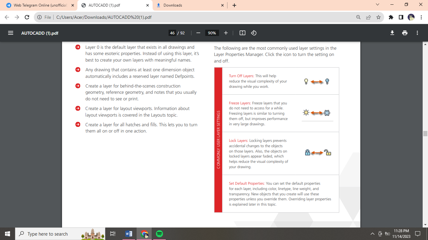
The following are the most commonly used layer settings in the Layer Properties Manager. Click the icon to turn the setting on and off.
Properties
You can assign properties such as color and linetype to individual objects, or as default properties assigned to layers.
The Properties Palette
The Properties palette is an essential tool. You can open it with the PROPERTIES command (enter PR in the Command window). The Properties palette displays a list of all the important property settings.
Match the Properties of Objects
For a fast way to copy the properties of a selected object to other objects, use the Match Properties tool, or enter MATCHPROP or MA in the Command window.
Lineweights
The Lineweight property provides a way to display different thicknesses for selected objects. The thickness of the lines remains constant regardless of the scale of the view.
Modifying
Perform editing operations such as erase, move, and trim on the objects in a drawing.
Erase
To erase an object, use the ERASE command. You can enter E in the Command window, or click the Erase tool.
Alternatively, before you enter any command, you can select several objects and then press the Delete key.
Select Multiple Objects
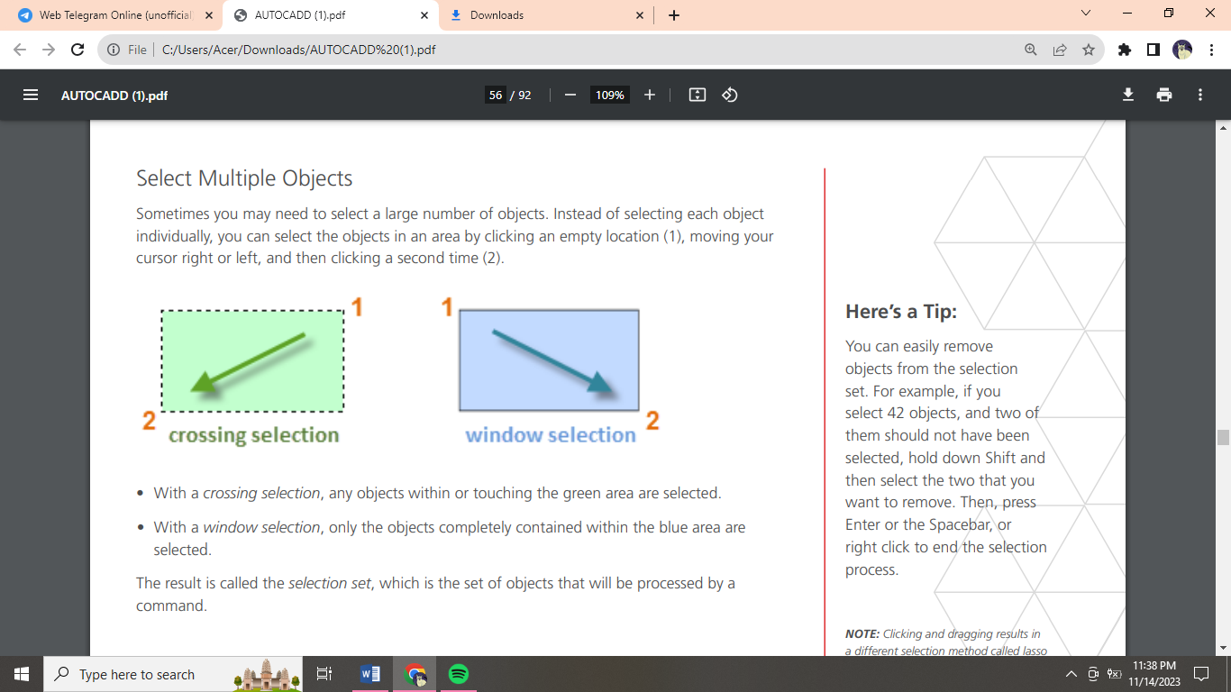
With a crossing selection, any objects within or touching the green area are selected.
With a window selection, only the objects completely contained within the blue area are selected.
The result is called the selection set, which is the set of objects that will be processed by a command.
You can easily remove objects from the selection set. For example, if you select 42 objects, and two of them should not have been selected, hold down Shift and then select the two that you want to remove. Then, press Enter or the Spacebar, or right click to end the selection process.
Move and Copy
Click the Copy tool or enter C.
The Distance Method
The Two Points Method
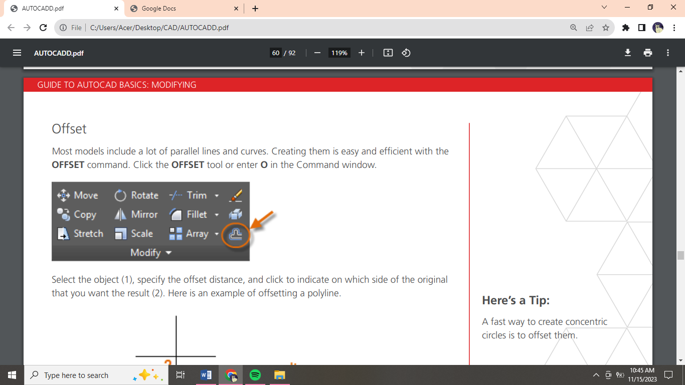 Offset
Most models include a lot of parallel lines and curves. Creating them is easy and efficient with the OFFSET command. Click the OFFSET tool or enter O in the Command window.
A fast way to create concentric circles is to offset them.
Trim and Extend
A popular technique is to use the OFFSET command in combination with the TRIM and EXTEND commands. In the Command window, you can enter TR for TRIM or EX for EXTEND. Trimming and extending are some of the most commonly used operations.
A faster method is to press Enter or the Spacebar right away instead of selecting any boundary objects.
Mirror
To begin the MIRROR command (or enter MI in the Command window). Always look for symmetry to save yourself extra work, even if the symmetry is not 100% identical.
Stretch
STRETCH command (or enter S in the Command window).
You can stretch most geometric objects. This lets you lengthen and shorten parts of your model.
Fillet
The FILLET command (enter F in the Command window) creates a rounded corner by creating an arc that is tangent to two selected objects.
If you specify 0 (zero) as the radius of the fillet (imagine a circle shrinking to a radius of 0), the result trims or extends the selected objects to a sharp corner.
Explode
The EXPLODE command (enter X in the Command window) disassociates a compound object into its component parts. You can explode objects such as polylines, hatches, and blocks (symbols). After you explode a compound object, you can modify each resulting individual object.
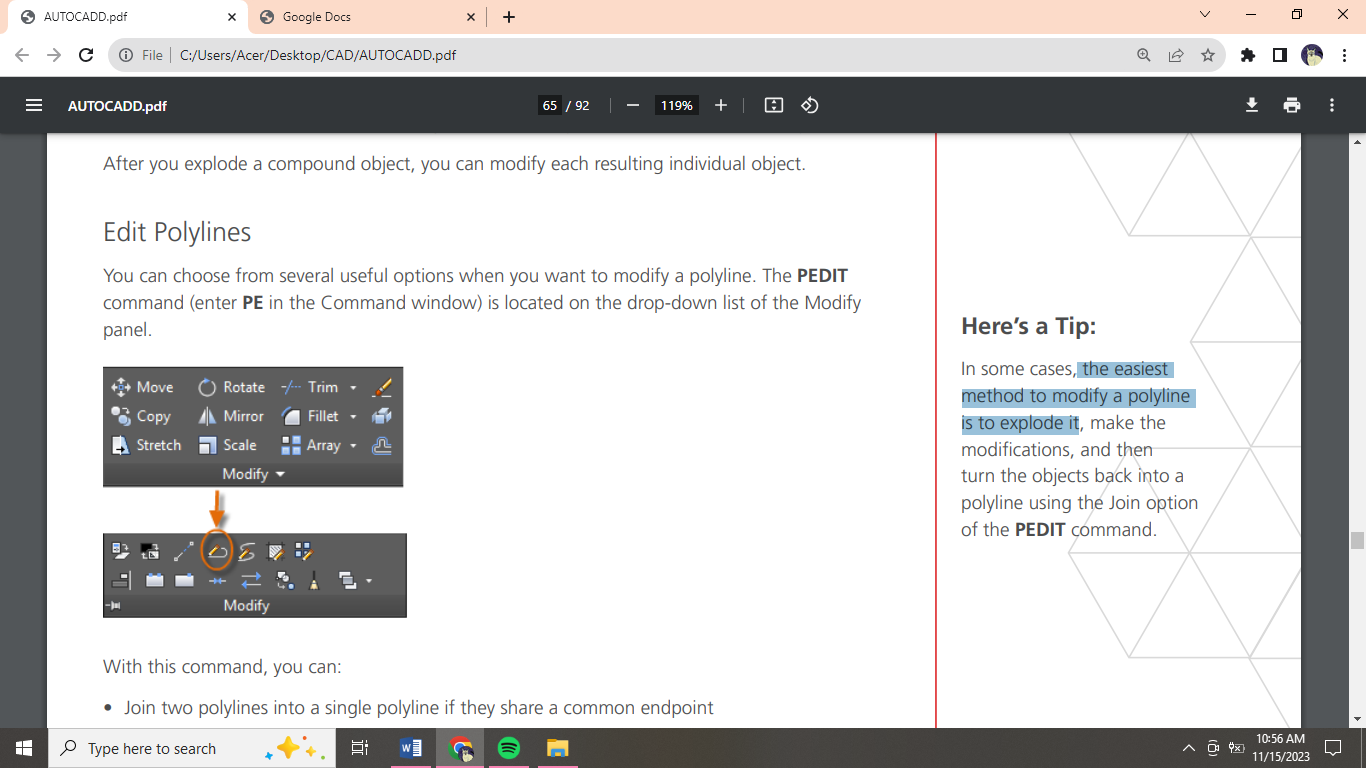
Edit Polylines
You can choose from several useful options when you want to modify a polyline. The PEDIT command (enter PE in the Command window) is located on the drop-down list of the Modify panel.
The easiest method to modify a polyline is to explode it.
Grips
Grips are displayed when you select an object without starting a command. Grips are often handy for light editing.
Blocks
Insert symbols and details into your drawings from commercial online sources or from your own designs.
In AutoCAD, a block is a collection of objects that are combined into a single named object.
Notice that when you insert a block, it is attached to your cursor at the point indicated. This location is called the insertion point.
You can create block definitions that include one or more attributes that store and display information. The command that you would use is ATTDEF. Typically, attributes include data such as part number, name, cost, and date.
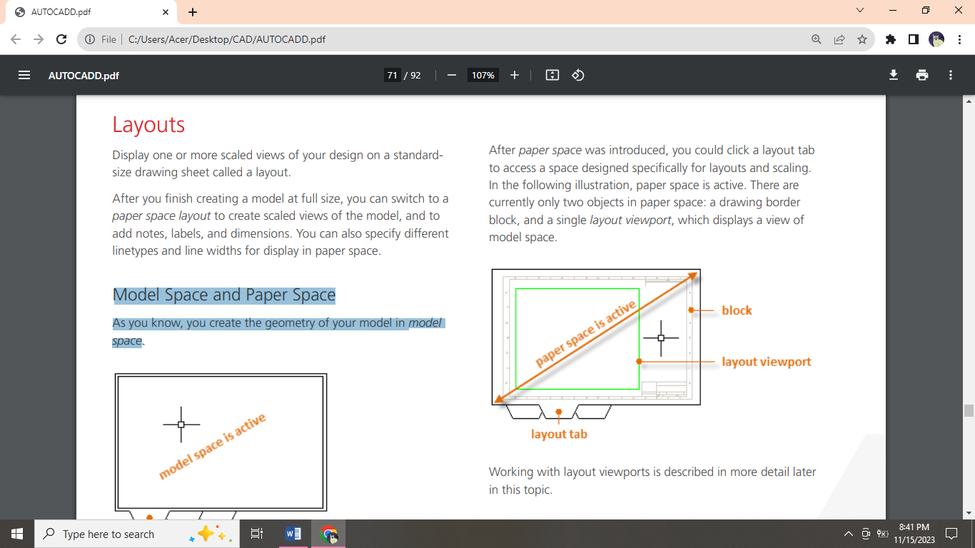
Layouts
Display one or more scaled views of your design on a standardsize drawing sheet called a layout.
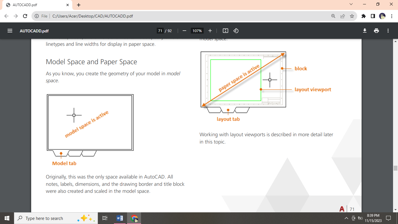
Model Space and Paper Space
As you know, you create the geometry of your model in model space.
Four Methods for Scaling
There are four different methods in AutoCAD that are used to scale views, notes, labels, and dimensions. Each method has its advantages depending on how the drawing will be used. Here’s a brief summary of each of the methods:
The Original Method: You create geometry, annotate, and print from model space. Dimensions, notes, and labels must all be scaled in reverse. You set the dimension scale to the inverse of the plot scale. With this method, scaling requires a little math. Many AutoCAD drawings were created with this method, and many companies still use it.
The Layout Method: You create geometry and annotate in model space, and print from the layout. Set the dimension scale to 0 and the dimensions will scale automatically.
The Annotative Method: You create geometry in model space, create annotative dimensions, notes, and labels (using a special annotative style) in model space from the layout, and you print from the layout. Annotative objects display only in layout viewports that share the same scale. The dimension scale is automatically set to 0 and all annotative objects scale automatically.
The Trans-Spatial Method: You create geometry in model space, create annotations in paper space on a layout with dimension scale set to 1, and you print from the layout. This is arguably the easiest, most direct method, and it is the method of choice for this guide.
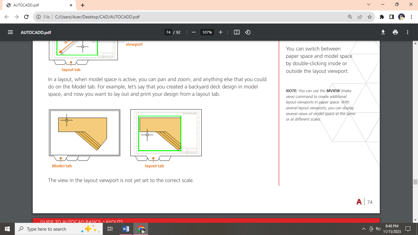
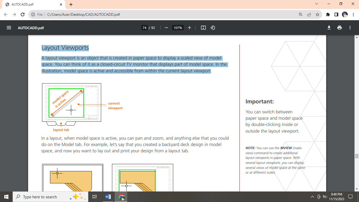
Layout Viewports
A layout viewport is an object that is created in paper space to display a scaled view of model space. You can think of it as a closed-circuit TV monitor that displays part of model space. In the illustration, model space is active and accessible from within the current layout viewport. You can use the MVIEW (make view) command to create additional layout viewports in paper space.
Notes and Labels
Create notes, labels, bubbles, and callouts. Save and restore style settings by name. You can create general notes using the MTEXT command (or enter MT in the Command window), which stands for multiline text. You can use the Properties palette to control the text style used for one or more selected multiline text objects.
Create a Text Style
As with several other annotation features, multiline text provides a lot of settings. You can save these settings as a text style using the STYLE command, and then you can access the text styles you’ve saved by clicking the drop-down arrow on the Annotation panel.
Multileaders
Multileader objects are used to create text with leader lines such as general labels, reference labels, bubbles, and callouts. Create a Multileader to create a multileader, use the MLEADER command. Click the Multileader tool in the Annotation panel or enter MLD in the Command window.
Create a Multileader Style
You can create your own multileader styles from the drop-down list in the expanded Annotation panel, or by entering MLEADERSTYLE in the Command window.
Dimensions
Linear Dimensions: You can create horizontal, vertical, aligned, and radial dimensions with the DIM command. The type of dimension depends on the object that you select and the direction that you drag the dimension line.
Dimension Styles
Dimension styles help establish and enforce drafting standards. There are many dimension variables that can be set with the DIMSTYLE command to control virtually every nuance of the appearance and behavior of dimensions.
The default dimension style is named either Standard (imperial) or ISO-25 (metric).
Printing
The command to output a drawing is PLOT and you can access it from the Quick Access toolbar.
Create a Page Setup
To open the Page Setup Manager, right-click on the Model tab or a layout tab and choose Page Setup Manager. The command is PAGESETUP.
DRAW

MODIFY

ANNOTATION

LAYERS

 BLOCK
BLOCK
 PROPERTIES
 GROUP
GROUP
 INSERT > BLOCK