Lecture 4: Depth Determination
Basic Principles
Requires specific knowledge of the following:
medium or body of water
underwater acoustics
devices available for depth measurement
complementary sensors for attitude and heave measurement
proper procedures to achieve and meet the internationally recommended standards (based on International Hydrographic Organization productions) for accuracy and coverage system
Methods
Lead line/sounding weight
It involves a heavy weight (often called a "lead") attached to a line, which is lowered vertically into the water from a boat to the seabed or riverbed. The depth is determined by the length of the line between the water surface and the bottom.
1 fathom = 6 feet
Stream measurements using sounding pole
This method is commonly used in shallow rivers and streams where using more complex equipment isn’t feasible. It involves a long pole with markings (or a graduated scale) that is manually lowered into the water to measure the depth at different points
Echosounding
It works by sending sound waves from a transducer at the surface, which travel through the water, bounce off the seafloor, and return to the transducer. The depth is calculated by measuring the time it takes for the sound waves to travel to the bottom and back.
Light Detection and Ranging (LiDAR)
LiDAR is a remote sensing technology that uses laser pulses to measure distances to the seafloor. It is typically used for mapping coastal regions, lakes, rivers, or shallow waters. It can be airborne or waterborne
Calculating Depth
Depth is determined from observation of travel time of acoustic waves
Acoustic pulse transmitted by a transducer travels through the column of water and is then reflected by the target (sea floor) back to the hydrophone
Depth is calculated from the measured travel time ∆t

Terminologies
Decibels (dB)
Scale used to describe a measurement unit of sound
Source Level Sound
Amount of energy transmitted into the water column
Expressed in units of decibels that describe the intensity of sound relative to a reference intensity at one unit distance from the sound source
Sound Propagation
Behavior of sound when interacting with boundaries and water column components
Types:
Spreading Loss
effect of the transmitted sound pulse spreading out in all directions
Power of an acoustic pulse = Intensity * Area
Attenuation Loss
effect of transmitted pulse being either scattered or absorbed (in the water medium or into the seafloor)
Echosounding
Types of Echosounders:
Single-beam echosounder (SBES)
Emits a single, vertical sound pulse directly beneath the vessel.
Provides depth information at a single point directly under the transducer.
Multi-beam echosounder (MBES)
Emits multiple sound beams in a fan-shaped pattern across a wide swath beneath the vessel.
Sweep System
Uses multiple single-beam transducers mounted at fixed angles on a boom or a frame.
Covers an area across a wider path by sweeping the beams side-to-side.
Swath System
True multi-beam system using a single transducer array.
Provides a continuous swath of depth measurements across the seafloor.
More advanced, with real-time 3D imaging and high data density.
Narrow beam
More focused and accurate depth readings.
Higher resolution of the bottom profile.
Better for detecting small features on the seafloor.
Ideal for detailed surveys (e.g., harbor inspections, underwater structures).
Wide beam
Covers a larger area but with less detail.
More prone to errors due to side-lobe reflections and averaging over larger footprints.
Useful for general depth sounding in large open areas where high detail isn’t critical.
Echosounder Components
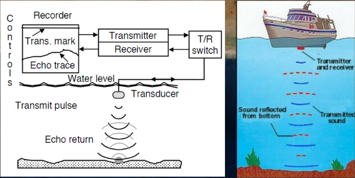
Transmitter
Quartz clock
controls the precise timing of when the pulses are sent—very important for accurate depth calculations.
Generates pulses at a certain frequency
Low vs High frequency
T/R Switch
Acts as a gate that controls the flow of electrical energy.
Passes the power from the transmitter to the transducer
Used to trigger a pulse with a specific length
Controls the pulse length (duration of each ping)
Transducer
To convert electrical power into acoustic power
To send the acoustic signal into the water
To receive the echo of the acoustic signal
To convert the acoustic signal into an electrical signal
Receiver
Takes the weak return signal (echo) and amplifies it so it can be processed.
Filters out unwanted noise or interference.
Ensures the signal is clean and strong enough to interpret.
Recorder
Takes the amplified signal and creates a visual or digital output.
Acoustic Parameters
Frequency
Attenuation of acoustic signal in water
Bandwidth
The range of frequencies used in a pulse.
Wider bandwidth = better resolution and target separation.
Helps distinguish closely spaced objects or fine features on the seabed.
Resonance f = f of max power transmission
Pulse Length or Width
The duration of each transmitted sound pulse (measured in milliseconds or microseconds).
Determines the amount of energy put into the water per pulse.
Sources of Errors and Corrections
Errors
Mounting angle
Instrument Offset
Incorrect Sound Velocity Profile
Draft measurements
Tidal variations
Corrections
All depths must refer to a common datum
Corrections must be applied to the results of soundings in order to get chartered depths which refer to the defined datum
Account possible sources of errors
Corrected depth is obtained as the sum of:
Observed depth
Instrumental corrections
Sound velocity correction (discrepancy between actual and constant velocity used by the sounder to derive depth)
Dynamic draft correction
Static draft (depth of transducer when the vessel is at rest)
Settlement (difference between rest and underway positions)
Squat (change in trim when underway)
Water level (tidal correction)