D.A.I.R. & Scan Tools
DETERMINING AND INTERPRETING READINGS
The DSO is nothing more than a voltmeter that plots the voltage over time, providing a graphical display or picture of what is happening in the circuit being tested. For example, a common cause of tip-in hesitation is an intermittent loss of signal from the Throttle Position Sensor (TPS). You can’t see it on the DMM because the problem occurs too fast for the tool to catch. But on a scope, the loss will be immediately seen as you trace the sensor signal on your screen while opening and closing the throttle.
Often you may need to compare the pattern on your scope with a “known good” pattern from another vehicle. You can find several sources for these patterns online.
In all cases, think of the pattern on the scope screen the same as you would the numbers on your multimeter and consider what is happening in the circuit you are testing. Is the full range of voltage present? Are there anomalies in the pattern? Is the signal ground showing signs of improper voltage drop?
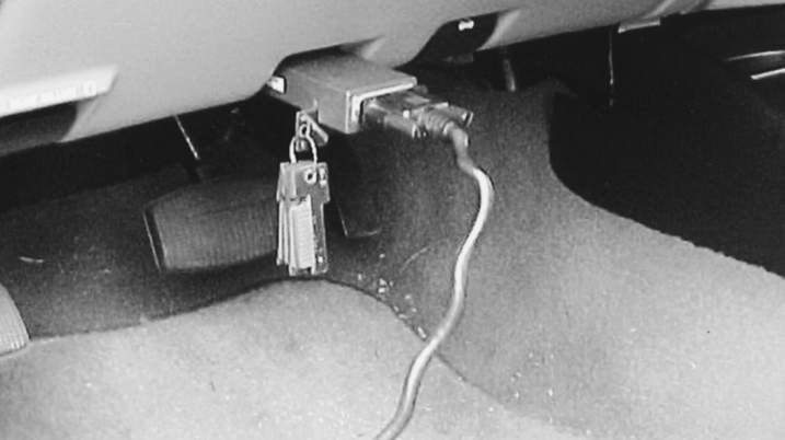
A scan tool connected to the DLC on an OBD II vehicle.
SCAN TOOLS
A scan tool is a diagnostic tool that connects to the DLC (Data Link Connector) to communicate with the vehicle’s computers. Scan tools can be used to read DTCs (Diagnostic Trouble Codes), perform tests and monitor specific system data.
Scan tools show a text display of labeled values determined by the manufacturer’s control systems and the programming module used in the scan tool. The display can be reorganized, frozen, recorded and interpreted, depending on the unit and can often present its data on a separate monitor, which is usually easier to view. Today’s scan tools also graph values of processed data Including electrical, pressure, vacuum, temperatures, etc. much as does the oscilloscope. The technician can quickly determine failed or out of range components, and also whether or not the failure is module related or is the result of a peripheral component or wiring.
OE scan tools are available direct from the manufacturer providing all technicians with the same data access. Many aftermarket scan tools offer similar accessibility at a lower cost. Both sources offer tooling that can be either handheld units or PC-based, with software updates typically available as internet downloads. Before using any scan tool, read manufacturer instructions to become familiar with its operation.
Make sure the ignition key is in the OFF position when connecting a scan tool cable connector to the DLC. On pre-OBD II vehicles (1995 and earlier), an adapter may have to be used. If the scan tool is not powered through the DLC, connect the power lead(s) to the cigarette lighter or battery.
The scan tool may ask you certain questions to identify the vehicle being serviced. Most scan tools have buttons or knobs with which to input information. Once the vehicle is identified, you can then select the desired diagnostic information.
DTCs are the most common requested information. Prior to OBD II, vehicle manufacturers used two and three digit codes that were proprietary to specific vehicles and systems and each manufacturer also had their own code definitions. With OBD II, common codes and definitions were developed to identify all basic emissions-related failures ((Refer to the Society of Automotive Engineers (SAE) Recommended Practice document J2012)) OBD II trouble codes consist of one alpha character followed by four digits. The alpha character indicates the area of the vehicle where the failure occurred. This includes (B) Body, (C) Chassis, (P) Powertrain, and (U) Network. The first digit of the DTC denotes the origin of the code. Codes authored by the SAE are identified by a zero (0). These codes are known as generic DTCs since they are the same for every vehicle. Manufacturer specific codes are indicated by the number one (1). These DTCs are part of the manufacturer’s enhanced diagnostic software, and vary between vehicle brands. The second digit in the DTC identifies the system experiencing the problem, while the last two digits correspond to a specific code definition.
In addition to accessing DTCs, modern scan tools can also display datastream values known as PIDs, (short for Parameter IDentification). OBD-II PIDs are codes used to request data from a vehicle. SAE standard J1979 defines many PIDs, but manufacturers also have their own specific to their vehicles. These data-stream values include the electrical operating values of the sensors, actuators and circuits in the engine control system. The displayed values can then be compared with specifications in the service manual.
Most scan tools provide “snapshot” data. This allows the technician to record problems while driving the vehicle. If there is an intermittent or condition–specific problem, the technician can takes a ‘snapshot’ of the engine control system operating conditions and PIDs, capturing the various sensor readings when the malfunction occurs. The technician can then review the information back at the shop to find the cause of the problem.
Some scan tools can be used to perform tests and are known as bi-directional scan tools. The scan tool can activate various switches and actuators and then tell you whether a component is functioning properly.
Today, technicians are more and more using dedicated laptops and notebook PCs in the service bay for downloading manufacturer-specific diagnostic programs, facilitating PCM reflashes, and more. An interface device is used between the PC and the vehicle’s data link connector. This topic is covered in more detail later in this guide. The software programs offered by many manufacturers today offer just-in-time repair instructions for the technician to follow. They lead the technician from finding fault code data to the most likely causes, and then indicate for the specific vehicle and model were to diagnose the respective fault(s) and how to perform the needed repairs.