knowt logo

BIOPHYSICS LABORATORY- FINALS

NOTES FOR FINALS

EXPERIMENT 9: HYDROSTATIC PRESSURE

OBJECTIVES: To study the variation of pressure with depth in a liquid

APPARATUS:

  • Hollow uniform cylinder

  • hydrometer jar

  • set of masses

  • vernier caliper

  • tap water

  • brine

DATA AND RESULTS

CALCULATIONS:
No description available.

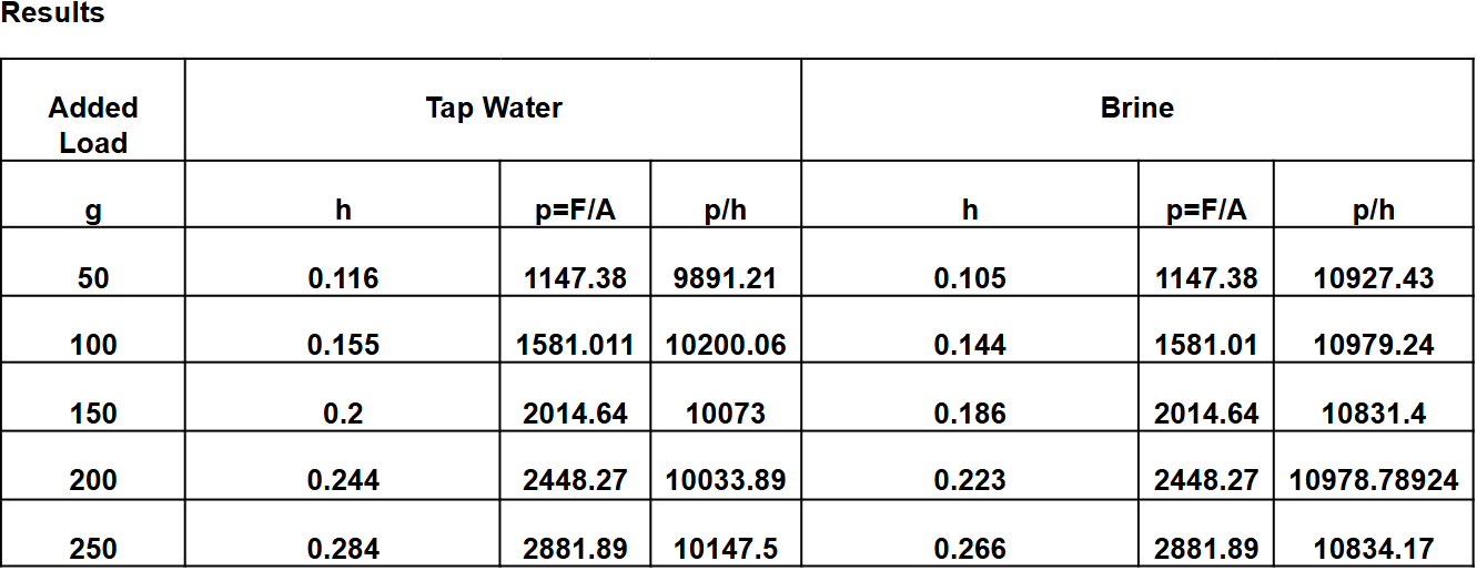
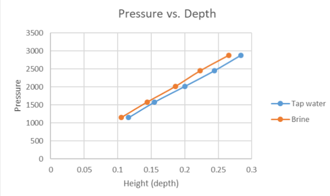
  • It is observed that the slope of the brine is relatively higher compared to the tap water. This can be interpreted as when the pressure is applied both, the brine has lesser depth compared to the tap water as it requires more pressure to increase the depth.

What can you say about the difference between the curves due to that tap water and due to brine?

  • Brine exerts higher pressure per unit height than tap water at every load level, increasing the difference as the load rises. This is likely due to the brine's greater density, resulting in a steeper pressure-load relationship.


EXPERIMENT 10: ARCHIMEDES PRINCIPLES

OBJECTIVES: To determine the buoyant force acting on a floating and on a sinking object.

APPARATUS:

  • Overflow can

  • Catch bucket

  • Metal cylinder/ metal cube

  • wooden block

  • string

  • beam balance

  • spring scale

  • water

  • alcohol

DATA AND RESULTS:

No description available.

Is the weight of the collected liquid in the catch bucket equal to the weight of the floating object? Why or why not?

  • In this experiment, the weight of liquid displaced is not significantly different from the weight of the object, with only a small percentage difference. This is because, according to Archimedes’ principle, the weight of the object floating on a liquid surface should be equal to the weight of its displaced liquid.

Is the weight of the object in air minus the weight of the object in liquid equal to the weight of the collected liquid? Why or why not?

  • The weight of an object in air minus its weight in liquid equals the buoyant force, which corresponds to the weight of the displaced liquid, not the collected liquid.

Does a floating object sink more in a liquid with low density than in a liquid with high density? Why or why not?

  • Whether an object sinks or floats depends on both the density of the object and the liquid.  An object will float on a liquid with high and low density so long as the object’s density is lesser than that of the liquid.   An object with less density will float because the buoyant force is greater than the gravitational pull on the object.


EXPERIMENT 11: MEASURING RESISTANCE (OHM’S LAW)

OBJECTIVES:

  1. To have an actual experience with resistance

  2. To learn how to use the multitester as an ohmmeter

  3. To learn how to read resistor color codes.

  4. To learn how to take safe action/s when dealing with electricity

APPARATUS:

  • Multitester

  • 5 resistors

DATA AND RESULTS

No description available.

How can one avoid getting electrocuted?

  • Avoid working near electric lines if possible. This may be inevitable, as some construction or utility workers may be brought to work near utility lines.


Cite Advantages and Disadvantages of resistor color-coding.

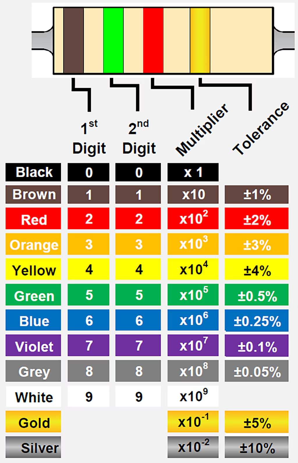
  • Advantages: Resistor Color Coding uses colored bands to quickly identify a resistors resistive value and its percentage of tolerance with the physical size of the resistor indicating its wattage rating.

  • Disadvantages: When a resistor is overheated, the colors change slightly. Therefore, it may be hard to distinguish between them (especially brown, orange, and red colors). It would also be difficult to use for colorblind people.

An engineer applies a potential difference of 3.80 V between the ends of a wire that is 2.50 m in length and 0.654 mm in radius. The resulting current through the wire is 17.6 A. What is the resistivity of the wire?

No description available.


EXPERIMENT 12: RESISTORS IN SERIES AND PARALLEL

OBJECTIVES:

  1. To be able to relate theoretical explanations to actual situations.

  2. To know how resistors behave when connected in series and in parallel.

APPARATUS:

  • Multimeter

  • Resistors: R1= 100Ω, R1= 200Ω, R1= 300Ω, and a third resistor of unknown value

  • Connectors

  • Trainer board

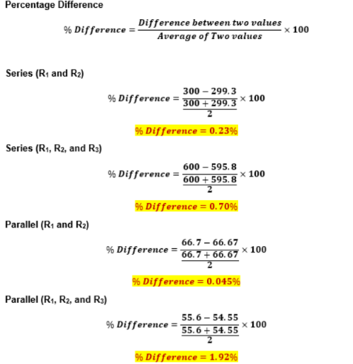
DATA AND RESULTS


EXPERIMENT 13: REFLECTION BY PLANE MIRRORS

OBJECTIVES: To determine experimentally the behavior of the image formed by a plane mirror.


APPARATUS:

  • Plane mirror on a wooden block

  • Ruler

  • Protractor

  • Pins

  • Bond paper


DATA AND RESULTS

How do the angle of incidence and the angles of reflection through points O and P in procedure 8 compare? Explain this phenomenon.

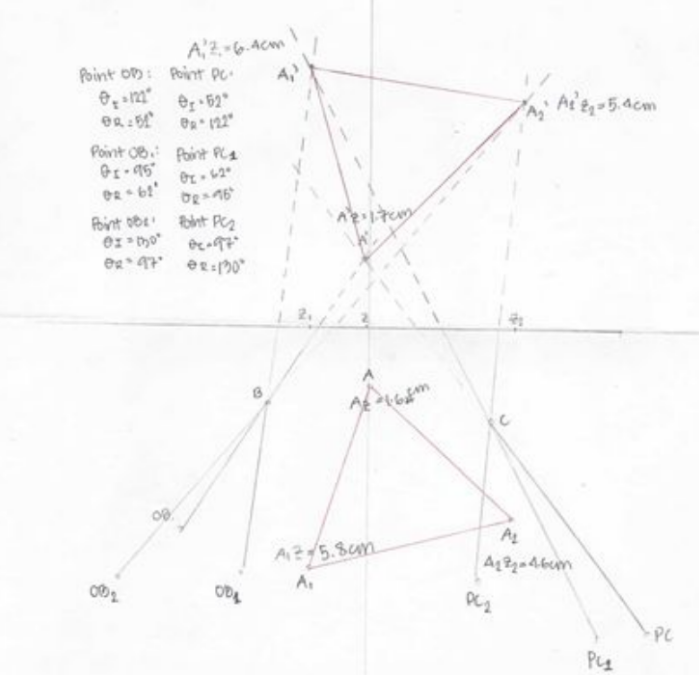
  • The law of reflection states that in an ideal setup, the angle of incidence (θI) and the angle of reflection (θR) must be equal. Based on the data in this experiment, when comparing the angle of incidence and the angles of reflection, Point O and Point P are approximately equal. For instance, at Point O, one measurement shows θI = 122° and θR = 52°, while another one shows θI = 95° and θR = 62°. The same goes at Point P, such as θI = 62° and θR = 95°. 


How do the distances of the object and the image from the mirror compare in procedure 9?

  • The distances of the object (A) and the image (A’) from the mirror are AZ = 1.45 cm and A’Z = 1.65 cm, respectively. Ideally, these distances should be equal, as the image produced by a plane mirror is virtual and located symmetrically on the opposite side of the mirror. Based on the data, while there is a small discrepancy between AZ and A’Z, they are close enough to suggest that the general principles of reflection are being demonstrated.


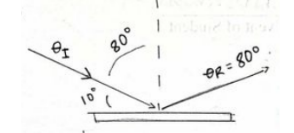
Light is incident on a flat surface, making an angle 10 degrees with the surface, as shown in the figure below.

  1. What is the angle of incidence?

  • θI = 90° -θsurface

  • θI = 90° -10°

  • θI = 80°

  • The angle of incidence is 80°.

  1. What is the angle of reflection?

  • θI = θR

  • θI = 80°

The law of reflection states that the angle of incidence (θI) and the angle of reflection (θR) are equal, therefore, the angle of reflection is 80°.

  1. Sketch the path of the reflected beam on the diagram.

EXPERIMENT 14: THIN SPHERICAL MIRRORS

OBJECTIVES: To study the different types of images formed by spherical mirrors.


APPARATUS:

  • Concave and convex mirrors

  • Meter stick

  • White cardboard as screen

  • Candle / light source

DATA AND RESULTS
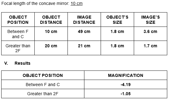
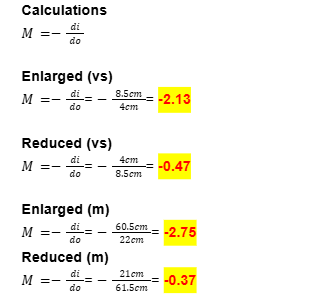
. Show your solution on the computation of magnification of the mirror.
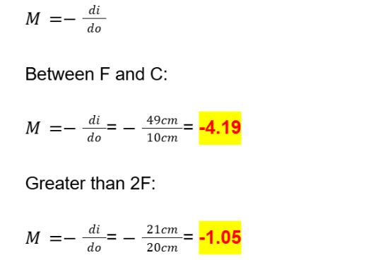
 Describe completely the image formed by procedure 4. Why is it so?  

  • The image was small and clear because the object distance was farther from the focal point of the mirror. When the object is placed beyond the center of curvature, the mirror produces a diminished, inverted, and real image, which can be easily captured on a screen. This occurs due to the convergence of light rays at a specific point after reflection.

Describe the image formed in procedure 5, 6, 7, and 8. Why is it so?  

  • The image was large, clear, but slightly blurry in some instances, as the positioning of the object or screen might not have been perfectly aligned. The image appears inverted when projected on the white screen. This is because parallel incident rays converge at the focal point after reflection, a property of concave mirrors, which are converging mirrors. This results in a magnified and real image when the object is placed between the focal point and the center of curvature.

Cite important applications of spherical mirrors.  

  • Satellite Dishes (Concave): Used to gather electromagnetic signals and reflect them onto a receiver or sensor positioned at the focal point.  

  • Rearview Mirrors (Convex): Provide a wider field of view to help drivers monitor the road behind them.  

  • Makeup or Shaving Mirrors (Concave): Magnify the image for detailed viewing, as they produce a larger, upright virtual image when the object is within the focal length.  

  • Telescope Mirrors (Concave): Collect and focus light from distant celestial objects, enabling clear magnified observations.  

  • Flashlights or Car Headlights (Concave): Reflect light to produce a concentrated beam that travels over long distances.  

  • Street Safety Mirrors (Convex): Allow drivers to see around blind corners by providing a broad field of vision.


EXPERIMENT 15: IMAGE FORMATION BY THIN LENSES


OBJECTIVES: To observe and examine the different kinds of images formed by both convex and concave lenses.


APPARATUS:

  • Convex lens

  • Concave lens

  • Lens holder

  • Meter stick

  • Cardboard screen

  • Screen holder

  • Light source

DATA AND RESULTS

How can you tell whether a lens is convex or concave just by touching it?

  • A convex lens feels thicker in the center and thinner at the edges, while a concave lens feels thinner in the center and thicker at the edges.

Where must the object be placed so that the image formed by a convex lens is virtual? How does the object distance compare with the focal length?

  • The object must be placed inside the focal length of the convex lens. The object distance must be less than the focal length.

Compare the magnification of the enlarged image and the reduced image. What do you notice?

  • The enlarged image has a higher magnification (-2.13) with a shorter object distance (4 cm), while the reduced image has a lower magnification (-0.471) with a longer object distance (8.5 cm). Magnification decreases as object distance increases.

Using the values do and di of the enlarged image, calculate the value of the focal point using the equation

1/f=1/do+1/di

How does it compare with the measured value of the focal length?

Calculated focal length: f=2.72 cm
Measured focal length: f=12.5 cm

  • The calculated focal length is much smaller, suggesting experimental error or a different lens system.


SUMMARY OF IMAGES FORMED BY MIRRORS/LENS

Mirror/Lens Image Formed

Plane Mirror

Always virtual, upright, same size, and behind the mirror.

Concave Mirror

- Far from the mirror: Real, inverted, smaller.

- Close to the mirror: Real, inverted, larger.

- At focal point: No image (light rays parallel).

- Very close: Virtual, upright, larger.

Convex Mirror

Always virtual, upright, and smaller.

Concave Lens

Always virtual, upright, and smaller.

Convex Lens

- Far from the lens: Real, inverted, smaller.

- Close to the lens: Real, inverted, larger.

- At focal point: No image (light rays parallel).

- Very close: Virtual, upright, larger.

KF

BIOPHYSICS LABORATORY- FINALS

NOTES FOR FINALS

EXPERIMENT 9: HYDROSTATIC PRESSURE

OBJECTIVES: To study the variation of pressure with depth in a liquid

APPARATUS:

  • Hollow uniform cylinder

  • hydrometer jar

  • set of masses

  • vernier caliper

  • tap water

  • brine

DATA AND RESULTS

CALCULATIONS:

No description available.

  • It is observed that the slope of the brine is relatively higher compared to the tap water. This can be interpreted as when the pressure is applied both, the brine has lesser depth compared to the tap water as it requires more pressure to increase the depth.

What can you say about the difference between the curves due to that tap water and due to brine?

  • Brine exerts higher pressure per unit height than tap water at every load level, increasing the difference as the load rises. This is likely due to the brine's greater density, resulting in a steeper pressure-load relationship.


EXPERIMENT 10: ARCHIMEDES PRINCIPLES

OBJECTIVES: To determine the buoyant force acting on a floating and on a sinking object.

APPARATUS:

  • Overflow can

  • Catch bucket

  • Metal cylinder/ metal cube

  • wooden block

  • string

  • beam balance

  • spring scale

  • water

  • alcohol

DATA AND RESULTS:

No description available.

Is the weight of the collected liquid in the catch bucket equal to the weight of the floating object? Why or why not?

  • In this experiment, the weight of liquid displaced is not significantly different from the weight of the object, with only a small percentage difference. This is because, according to Archimedes’ principle, the weight of the object floating on a liquid surface should be equal to the weight of its displaced liquid.

Is the weight of the object in air minus the weight of the object in liquid equal to the weight of the collected liquid? Why or why not?

  • The weight of an object in air minus its weight in liquid equals the buoyant force, which corresponds to the weight of the displaced liquid, not the collected liquid.

Does a floating object sink more in a liquid with low density than in a liquid with high density? Why or why not?

  • Whether an object sinks or floats depends on both the density of the object and the liquid.  An object will float on a liquid with high and low density so long as the object’s density is lesser than that of the liquid.   An object with less density will float because the buoyant force is greater than the gravitational pull on the object.


EXPERIMENT 11: MEASURING RESISTANCE (OHM’S LAW)

OBJECTIVES:

  1. To have an actual experience with resistance

  2. To learn how to use the multitester as an ohmmeter

  3. To learn how to read resistor color codes.

  4. To learn how to take safe action/s when dealing with electricity

APPARATUS:

  • Multitester

  • 5 resistors

DATA AND RESULTS

No description available.

How can one avoid getting electrocuted?

  • Avoid working near electric lines if possible. This may be inevitable, as some construction or utility workers may be brought to work near utility lines.


Cite Advantages and Disadvantages of resistor color-coding.

  • Advantages: Resistor Color Coding uses colored bands to quickly identify a resistors resistive value and its percentage of tolerance with the physical size of the resistor indicating its wattage rating.

  • Disadvantages: When a resistor is overheated, the colors change slightly. Therefore, it may be hard to distinguish between them (especially brown, orange, and red colors). It would also be difficult to use for colorblind people.

An engineer applies a potential difference of 3.80 V between the ends of a wire that is 2.50 m in length and 0.654 mm in radius. The resulting current through the wire is 17.6 A. What is the resistivity of the wire?

No description available.


EXPERIMENT 12: RESISTORS IN SERIES AND PARALLEL

OBJECTIVES:

  1. To be able to relate theoretical explanations to actual situations.

  2. To know how resistors behave when connected in series and in parallel.

APPARATUS:

  • Multimeter

  • Resistors: R1= 100Ω, R1= 200Ω, R1= 300Ω, and a third resistor of unknown value

  • Connectors

  • Trainer board

DATA AND RESULTS


EXPERIMENT 13: REFLECTION BY PLANE MIRRORS

OBJECTIVES: To determine experimentally the behavior of the image formed by a plane mirror.


APPARATUS:

  • Plane mirror on a wooden block

  • Ruler

  • Protractor

  • Pins

  • Bond paper


DATA AND RESULTS

How do the angle of incidence and the angles of reflection through points O and P in procedure 8 compare? Explain this phenomenon.

  • The law of reflection states that in an ideal setup, the angle of incidence (θI) and the angle of reflection (θR) must be equal. Based on the data in this experiment, when comparing the angle of incidence and the angles of reflection, Point O and Point P are approximately equal. For instance, at Point O, one measurement shows θI = 122° and θR = 52°, while another one shows θI = 95° and θR = 62°. The same goes at Point P, such as θI = 62° and θR = 95°. 


How do the distances of the object and the image from the mirror compare in procedure 9?

  • The distances of the object (A) and the image (A’) from the mirror are AZ = 1.45 cm and A’Z = 1.65 cm, respectively. Ideally, these distances should be equal, as the image produced by a plane mirror is virtual and located symmetrically on the opposite side of the mirror. Based on the data, while there is a small discrepancy between AZ and A’Z, they are close enough to suggest that the general principles of reflection are being demonstrated.


Light is incident on a flat surface, making an angle 10 degrees with the surface, as shown in the figure below.

  1. What is the angle of incidence?

  • θI = 90° -θsurface

  • θI = 90° -10°

  • θI = 80°

  • The angle of incidence is 80°.

  1. What is the angle of reflection?

  • θI = θR

  • θI = 80°

The law of reflection states that the angle of incidence (θI) and the angle of reflection (θR) are equal, therefore, the angle of reflection is 80°.

  1. Sketch the path of the reflected beam on the diagram.


EXPERIMENT 14: THIN SPHERICAL MIRRORS

OBJECTIVES: To study the different types of images formed by spherical mirrors.


APPARATUS:

  • Concave and convex mirrors

  • Meter stick

  • White cardboard as screen

  • Candle / light source

DATA AND RESULTS

. Show your solution on the computation of magnification of the mirror.

 Describe completely the image formed by procedure 4. Why is it so?  

  • The image was small and clear because the object distance was farther from the focal point of the mirror. When the object is placed beyond the center of curvature, the mirror produces a diminished, inverted, and real image, which can be easily captured on a screen. This occurs due to the convergence of light rays at a specific point after reflection.

Describe the image formed in procedure 5, 6, 7, and 8. Why is it so?  

  • The image was large, clear, but slightly blurry in some instances, as the positioning of the object or screen might not have been perfectly aligned. The image appears inverted when projected on the white screen. This is because parallel incident rays converge at the focal point after reflection, a property of concave mirrors, which are converging mirrors. This results in a magnified and real image when the object is placed between the focal point and the center of curvature.

Cite important applications of spherical mirrors.  

  • Satellite Dishes (Concave): Used to gather electromagnetic signals and reflect them onto a receiver or sensor positioned at the focal point.  

  • Rearview Mirrors (Convex): Provide a wider field of view to help drivers monitor the road behind them.  

  • Makeup or Shaving Mirrors (Concave): Magnify the image for detailed viewing, as they produce a larger, upright virtual image when the object is within the focal length.  

  • Telescope Mirrors (Concave): Collect and focus light from distant celestial objects, enabling clear magnified observations.  

  • Flashlights or Car Headlights (Concave): Reflect light to produce a concentrated beam that travels over long distances.  

  • Street Safety Mirrors (Convex): Allow drivers to see around blind corners by providing a broad field of vision.


EXPERIMENT 15: IMAGE FORMATION BY THIN LENSES


OBJECTIVES: To observe and examine the different kinds of images formed by both convex and concave lenses.


APPARATUS:

  • Convex lens

  • Concave lens

  • Lens holder

  • Meter stick

  • Cardboard screen

  • Screen holder

  • Light source

DATA AND RESULTS

How can you tell whether a lens is convex or concave just by touching it?

  • A convex lens feels thicker in the center and thinner at the edges, while a concave lens feels thinner in the center and thicker at the edges.

Where must the object be placed so that the image formed by a convex lens is virtual? How does the object distance compare with the focal length?

  • The object must be placed inside the focal length of the convex lens. The object distance must be less than the focal length.

Compare the magnification of the enlarged image and the reduced image. What do you notice?

  • The enlarged image has a higher magnification (-2.13) with a shorter object distance (4 cm), while the reduced image has a lower magnification (-0.471) with a longer object distance (8.5 cm). Magnification decreases as object distance increases.

Using the values do and di of the enlarged image, calculate the value of the focal point using the equation

1/f=1/do+1/di

How does it compare with the measured value of the focal length?

Calculated focal length: f=2.72 cm
Measured focal length: f=12.5 cm

  • The calculated focal length is much smaller, suggesting experimental error or a different lens system.


SUMMARY OF IMAGES FORMED BY MIRRORS/LENS

Mirror/Lens Image Formed

Plane Mirror

Always virtual, upright, same size, and behind the mirror.

Concave Mirror

- Far from the mirror: Real, inverted, smaller.

- Close to the mirror: Real, inverted, larger.

- At focal point: No image (light rays parallel).

- Very close: Virtual, upright, larger.

Convex Mirror

Always virtual, upright, and smaller.

Concave Lens

Always virtual, upright, and smaller.

Convex Lens

- Far from the lens: Real, inverted, smaller.

- Close to the lens: Real, inverted, larger.

- At focal point: No image (light rays parallel).

- Very close: Virtual, upright, larger.

robot