Protection Devices Flashcards
ower from a good battery is allowed to flow uncontrolled through a wire, such as a taillight with an unintended ground (or short circuit), the wire will become overheated and the insulation will smoke and burn. Since there’s little resistance, current flows through the wire in an overabundance. The heat generated will likely melt the wire. Obviously, battery voltage cannot be allowed to flow in an uncontrolled manner through all circuits. Circuit protection is needed, and understanding fuses, circuit breakers, fusible links and switches is a vital part of electrical fault diagnosis.
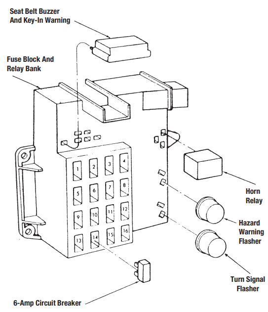
Details of a typical fuse panel.
FUSES
Most circuits in a vehicle are protected by fuses. A fuse is nothing more than a small section of electrical conductor with a known maximum current-carrying capability. If too much current is pulled through the fuse, the fuse will heat up, melt, and thus open the circuit to stop the excessive current flow. The fuse is designed to be the sacrificial part, giving its electrical life for the good of the circuit it protects. After the excessive electrical flow problem is corrected, a new fuse must be installed. Modern fuses are rated in amps by numbers - 15, 20, 30, etc. Higher-draw circuits require an increased level of circuit protection.
CIRCUIT BREAKERS
A popular circuit breaker in use today, known as a thermal unit, features coil windings wrapped around an iron core. The winding is connected in series with a current-carrying, bimetal blade. The bimetal blade terminates in a contact point that matches a stationary contact point. Normal current flow magnetizes the iron core to attract the bimetal arm. This helps hold the points closed.
Excessive current flow can be stopped when the bimetal arm overheats and curls up against magnetic pull, thus opening the breaker points to open the circuit. When current stops flowing in the circuit, the bimetal arm uncurls to close the points and close the circuit, allowing current to resume its flow.
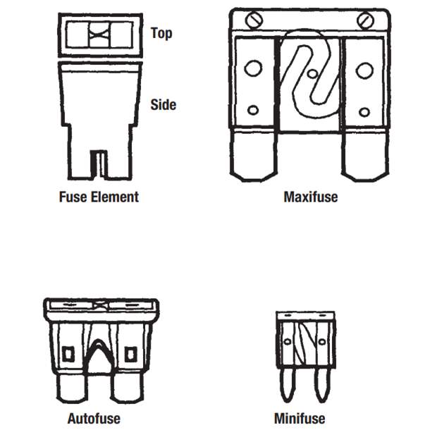
Typical automotive fuses. (Courtesy: GM Corp.)
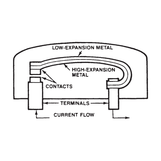
Functional view of a typical circuit breaker. (Courtesy: Ford Motor Co.)
The bimetal arm is actually two separate sections of metal welded together. One section of metal has more of an ability to expand with heat — that is, a higher coefficient of expansion — than the section to which it is welded. Since one section expands faster and farther than the metal to which it is attached, the overall effect is a curling-up action, which opens the breaker points. When the parts cool, the contacts touch once more, and current flow is restored. If too much current still flows, the breaker opens again.
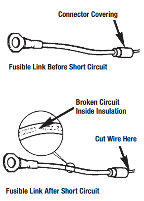
Examples of good and damaged fusible links. (Courtesy: GM Corp.)
FUSIBLE LINKS
A fusible link is a fused wire that protects a particular circuit from high currents, and may be in a harness or mounted separately, and performs the same function as the fuses in a fuse block.
Main circuits from the battery often include fusible links. If we want to protect a circuit made of 14-gauge (2.0mm) wire from possible current overload and damage, we would insert a small length of thinner (18- or 16-gauge) wire in series in the feed circuit. The fusible link size is typically two gauge sizes smaller than the wiring it protects.
A fusible link, then, is a short section (several inches or so) of smaller wire that protects a larger wire.
The lighter-gauge wire will overheat and melt when overloaded before the heavier 14-gauge wire is damaged. Thus, a damaged link may appear discolored or misshaped.
Fusible links are often identified by colored insulation — red, pink, brown, yellow, etc. The color indicates the amount of maximum circuit protection available. Several fusible links may be found inside a vehicle. For example, a fusible link at the battery terminal of the starting motor protects the complete vehicle wiring; a fusible link at the ignition terminal of the ignition switch protects the alternator field, and so on.
SWITCHES
Electrical circuits must be opened or closed on demand from the system or by the vehicle driver. Current will flow only in a closed circuit. Opening and closing a circuit is accomplished using a switch.
The simplest switch is a manual knife-blade assembly, which is little more than a movable conductor. To open a circuit, the movable conductor, often made of copper, is pulled, pushed, slid or rotated so that current can no longer flow through that circuit. A headlight switch is a mechanical switch in most installations; so are the heater switch, the courtesy light switch and others. The headlight switch is a little unusual in that it often incorporates a circuit breaker for headlight circuit protection. But it is still a simple mechanical switch. More complex switches also are used for circuits.
Switches may be of a double-throw design. This means the power coming into the switch may be directed in one of two directions, depending on the position of the switch’s two-way (or three-way) selector if of the “center off” type.
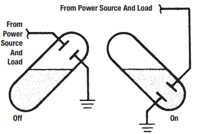
Typical Mercury switch. (Courtesy: Ford Motor Co.)
A switch also may be double-throw, double-pole. This means it has two or three positions, much like the single-pole, double-throw unit just discussed. But the double-pole version may complete or disconnect two separate circuits with one switching motion; it also may do the same when flipped in the opposite direction. This type of switch is used extensively in power windows and seats to reverse DC polarity to reverse motor direction. The switch puts the window up, down, or stops it (center off). When the switch is tripped, it makes both a power connection and a ground connection for the motor in its circuit.
Switches are operated by the movement of a diaphragm in response to pressure, such as in an oil pressure switch for a warning light.
Temperature sensitive switches usually have a bimetallic element that is heated electrically or by a component where the switch is used as a sensor. The bimetallic element consists of two kinds of metal, with different thermal expansion rates, that when attached to one another, the resulting assembly will bend in the direction of the metal that expands the least.
Mercury switches are used to detect motion. They are commonly used to turn on the hood and trunk lights when the lids are raised. The switch contains a capsule partially filled with mercury, with two electrical contacts at one end. The capsule is situated such that, when the lid is raised, the mercury flows to the end with the contacts, completing the circuit for the light.
Some switches are not hard wired to the circuit they control, but are input sensors to an electronic module. These switches are fed a reference voltage that is usually less than system voltage and return a varying voltage to the control module based on the switch’s position. For example, a headlight switch may send 5 volts to the body module when the lights are off, 3.5 volts when the running lights alone are on, and 1.7 volts when the headlights are added. The body module uses this signal to turn on the appropriate lights using drivers (internal switches) of its own. Control module drivers can complete the ground path of a circuit or provide power side voltage that may or may not be the same as system voltage at the battery. When diagnosing any circuit, be sure to read up on its proper operation and have a wiring schematic printed out and on hand.
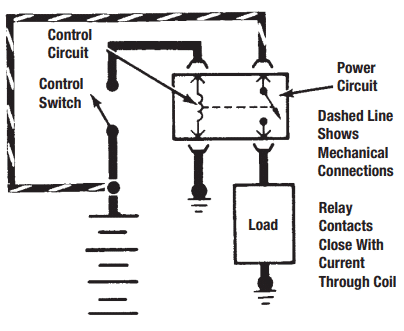
Typical relay circuit. (Courtesy: Ford Motor Co.)
RELAYS
A relay is basically a remotely operated magnetic mechanical switch. Relays allow a low control current to switch on or off higher amperage circuits. Relays may be normally off, or normally on. Some are double pole, double throw, or both. Relays may have many terminals, but in general, look for the three basic items: the hot power supply, the control ground and the power-out terminals. Most relays operate on these basic wiring terminal elements. The control voltage goes into the relay to energize the relay coil. This may be a separate feed or a common one with the main power feed.
The control circuit in one of the modules (ECM, PCM, TCM, etc.) sometimes provides a ground for the relay coil. So-called driver circuits in a module often provide a negative, or ground side, connection for the relay circuits they control. When the relay magnet energizes, the relay points close and power is allowed to go through the relay.
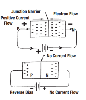
A diode is akin to an electrical switch. When voltage is connected in a forward mode, electrons will cross the junction barrier and current will start to flow. When voltage is connected in a reverse mode, no electrons flow across the junction barrier.
The relay coil is the control part of the relay, and has sufficient resistance to allow a safe current flow from the power source, through its windings, and back to ground through the ECM driver (in this example) for a complete circuit. All circuits make this circle. If the coil develops a short, it can allow too much current to flow through the driver, which can sometimes lead to replacement of the module.
A tip-off when examining a relay is sometimes found in the wire sizes. The hot power wires that drive lights, wipers and motors will usually be thicker than the control circuit wires. The smaller control circuit amperage controls the high-powered circuit and usually uses a lighter-gauge wire.
Whenever a relay is being replaced, make certain the correct part number for the application is used. Relays may often look alike but be wired for different functions or purposes. Many relays include diodes to prevent unwanted voltage spikes from reaching the parent control module. Failure to use the same relay can cause permanent damage to the module’s circuit board.
For fast and reliable switching or remote control of electrical devices, solid-state (no moving parts) transistors are often used instead of mechanical relays. On many later model vehicles, these relays are incorporated into a control module and are not serviceable separately. When troubleshooting these circuits, transistors do not tolerate test lights or low-Impedance analog meters which can overload and destroy sensitive solid-state components.
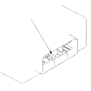
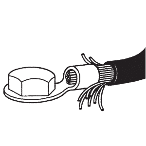
Before attaching a connector, make sure all terminals are in place and not bent. (Courtesy: Honda Motor Co., Ltd.)
Just because a terminal fastener is tight does not mean there is a good connection. There could be broken wire strands or a buildup of corrosion between the terminal and component, either of which could create additional resistance in the circuit. (Courtesy: Interstate Battery System of America)
DIODES
A diode is like an electrical check valve; a semiconductor that permits the flow of electricity in only one direction. Diodes are used to rectify the alternating current of an AC alternator and transform it into pulsating Direct Current (DC).
Diodes that have optical abilities also are important. Light-emitting diodes (LEDs) that produce red, yellow and green light are used as dashboard indictor lights, as well as in alphanumeric displays.
A diode can be checked using an ohmmeter. Put the red probes on the N-side; black on the P-side. Read the resistance, and then reverse the leads. The diode should have a high resistance in one direction only. Zener diodes use a calibrated reverse current to “clamp” circuits once they pass specified voltages.
WIRING REPAIRS
Many electrical problems are caused by damaged wiring and connectors. When troubleshooting circuits, carefully examine wires for breaks, melting, worn or damaged insulation, fraying, corrosion and oil contamination. Also, remember that even if a wire looks undamaged, it could still be broken inside the insulation. Checking for voltage drop while current is applied is a good method for testing for such faults.
Check connectors for damaged terminal housings, bent, broken or loose terminals, and corrosion. Check ring terminals for loose fasteners, corrosion or overheating.
If repairs are required, always follow the manufacturer’s recommendations listed in the service manual. Some manufacturers recommend replacing wiring harnesses for systems like the Supplemental Restraint System (SRS), rather than repairing them.
Although soldering is the preferred way to connect wires, solderless connectors can be used if properly crimped. When stripping the insulation from a wire, be careful not to cut any wire strands and only remove enough insulation to allow the wire to properly fit inside the connector. After crimping, use electrical tape or heat shrink tubing to seal the connection.
SOLDERING
Soldering is a quick, efficient method of joining metals permanently. Everyone who has to make wiring repairs should know how to solder. Electrical connections that are soldered are far less likely to come apart and will conduct electricity much better than connections that are only crimped together.
The most popular method of soldering is with an electrical soldering gun. Soldering irons are available in many sizes and wattage ratings. Irons with higher wattage ratings deliver higher temperatures and recover lost heat faster. A small soldering iron rated for no more than 50 watts is recommended, especially on electrical systems where excess heat can damage the components being soldered. Replacement of alternator pigtails requires a gun that is intended for heavy use, due to the high heat loss through the large diameter wires.
Three ingredients are necessary for successful soldering:
proper flux
good solder
sufficient heat
A soldering flux is necessary to clean the metal of tarnish, prepare it for soldering and enable the solder to spread into tiny crevices. When soldering, always use a rosin flux, or rosin core solder if available, which is non-corrosive and will not attract moisture once the job is finished. Other types of flux (acid core) will leave a residue that will attract moisture and cause wires to corrode.
Tin is a unique metal with a low melting point. In a molten state, it dissolves and easily forms alloys with many metals. Solder was formerly created by mixing tin with lead. The most common proportions were 40/60, 50/50 and 60/40, with the percentage of tin listed first. Today’s solders contain only tin, making them very difficult for a beginner to use because more heat is required to melt the solder. Always use solder that says “rosin core” on the package.
Contrary to popular belief, the purpose of the soldering iron is not to melt the solder itself, but to heat the parts being soldered to a temperature high enough to melt the solder when it touches the work. Solder usually melts between 360 and 460°F. Melting flux-cored solder on the soldering iron will usually destroy the effectiveness of the flux. Be sure to read up and practice soldering techniques before attempting automotive wiring or circuit board repairs. Use an alligator clip or needle-nose pliers when soldering leads on heat-sensitive components. Doing so acts provides a “heat-sink” to draw away heat from the component itself and prevent its possible destruction. Always use the lowest heat possible when replacing LEDs or other components on circuit boards, or repairing cracks on them with a solder bridge. Excessive heat will lift the printed circuit from the board and render it useless.