knowt logo

Electromagnetic Induction

1. Electromagnetic Induction

-Motional EMF:

  • Concept:

    • When a conductor moves through a magnetic field, it induces an electromotive force (EMF).

  • Physics:

    • Free electrons in the conductor experience a force due to the magnetic field, leading to a separation of charges and an electric field within the conductor.

  • Formula:

    • The induced EMF (ε) is given by ε=BvL, where

      • B is the magnetic field strength,

      • v is the velocity of the conductor, and

      • L is the length of the conductor perpendicular to the direction of motion.

  • Equilibrium:

    • The induced EMF continues until the electric force from the built-up charge balances the magnetic force, eε=evB.

-Magnetic Flux and Faraday’s Law

  • Magnetic Flux (Φ): Quantified as representing the total magnetic field moving through an area A at angle

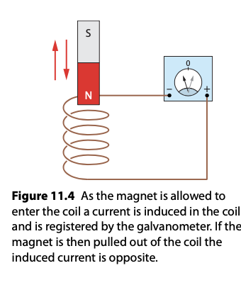
  • Faraday’s Law: The induced EMF in a circuit is equal to the negative rate of change of magnetic flux through the circuit
-Lenz’s Law:

  • The direction of the induced EMF and current is such that it opposes the change in magnetic flux that produced it, conserving energy.

  • Demonstrated by considering the direction of force on electrons due to the magnetic field and the resulting direction of current flow.

  • Applications and Implications

    • Lenz’s and Faraday’s laws are foundational for the functioning of electrical generators, transformers, and induction-based technologies.

    • The laws also provide a deeper understanding of the interplay between electricity and magnetism, showcasing the principle that changing magnetic fields can induce electrical currents.

-Transmission of Power

  • Alternating Current (AC)

    • AC is produced by an AC generator, where a coil rotating in a magnetic field induces an EMF due to electromagnetic induction.

    • AC changes direction periodically, with the EMF and current represented as sinusoidal functions over time.

  • The AC Generator

    • Converts mechanical energy into electrical energy using electromagnetic induction.

    • A coil rotates within a magnetic field, cutting through magnetic field lines, thus inducing an EMF and current.

    • The EMF (ε) Induced in the coil is proportional to the rate of change of magnetic flux, given by

      • ε=N(dΦ/dt)

        • N is the number of turns in the coil.

-Root Mean Square (RMS) Quantities
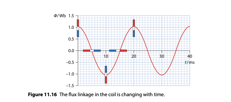
  • RMS values provide a measure of the equivalent steady DC values that would produce the same power.​

  • peak voltage and current respectively, divided by root 2, gives the respective rms values.

  • RMS values are used because power in an AC circuit depends on these average values rather than the peak values.

  • The Transformer:

    • A device that changes the voltage level of AC without changing its frequency through electromagnetic induction.

    • Consists of primary and secondary coils around a core, with the voltage change ratio determined by the ratio of turns in the coils

    • Power loss in transformers occurs mainly due to eddy currents, which are minimized by laminating the core, and magnetic hysteresis.

  • Transformers and Power Transmission:

    • Step-up transformers increase voltage, reducing current for efficient long-distance power transmission, minimising power loss (P=I2R)

    • Step-down transformers reduce voltage to safe levels for domestic and industrial use.

    • Power plants use high voltages to transmit power over long distances to reduce energy loss.

Diode Bridges and Rectification

  • Diode bridges convert AC to direct current (DC).

    • Half-wave rectification uses a single diode to allow current in only one direction, resulting in a loss of half the waveform.

    • Full-wave rectification uses a bridge rectifier to use both halves of the AC waveform, improving efficiency.

    • During one half-cycle, two diodes conduct, allowing current flow in one direction; during the opposite half-cycle, the other two diodes conduct, maintaining the direction of current flow.

2. Capacitance

  • Definition and Basic Concept:

    • Capacitance (C): The ability of a system to store charge per unit voltage, defined as C, where

      • q is the charge

      • V is the potential difference

      • Unit of capacitance is the farad (F), where 1 F = 1 C/V.

    • Capacitance of a Parallel Plate Capacitor

      • Depends on the geometry: where

        • d is the distance between plates

        • is the permittivity of the medium

        • A is the plate area.

  • Effect of Dielectric on Capacitance

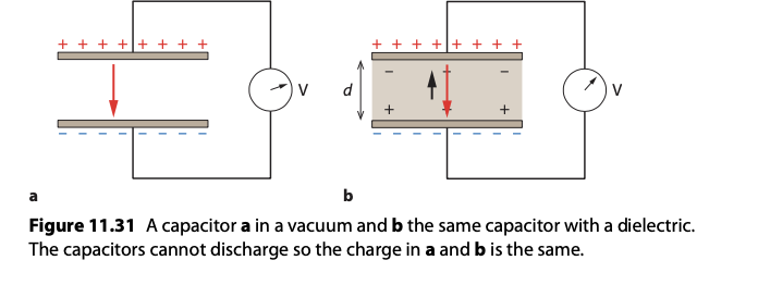
    • Inserting a dielectric material between the plates of a capacitor increases its capacitance by reducing the electric field, which allows the capacitor to store more charge for the same voltage.

    • Capacitors in Parallel and Series

      • Parallel Configuration:

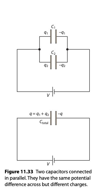
        • Capacitances add up ( Ctotal = C1+C2+C3…….)

      • Series Configuration:

        • Inverses of capacitances add up.

  • Energy Stored in a Capacitor

    • Represents the work done to charge the capacitor.

    • Charging and Discharging a Capacitor

      • Charging: When connected to a voltage source, the capacitor charges up following an exponential curve, approaching its maximum charge asymptotically.

      • Discharging: The stored energy in the capacitor is released when the circuit is closed, discharging exponentially to zero.

    • Capacitors in Rectification

      • Used in conjunction with diodes in power supply circuits to smooth the output from rectifiers.

      • During the half-cycle when the AC is in the correct direction, the capacitor charges up, and during the opposite half-cycle, it discharges, providing a more continuous DC output.

TK

Electromagnetic Induction

1. Electromagnetic Induction

-Motional EMF:

  • Concept:

    • When a conductor moves through a magnetic field, it induces an electromotive force (EMF).

  • Physics:

    • Free electrons in the conductor experience a force due to the magnetic field, leading to a separation of charges and an electric field within the conductor.

  • Formula:

    • The induced EMF (ε) is given by ε=BvL, where

      • B is the magnetic field strength,

      • v is the velocity of the conductor, and

      • L is the length of the conductor perpendicular to the direction of motion.

  • Equilibrium:

    • The induced EMF continues until the electric force from the built-up charge balances the magnetic force, eε=evB.

-Magnetic Flux and Faraday’s Law

  • Magnetic Flux (Φ): Quantified as representing the total magnetic field moving through an area A at angle

  • Faraday’s Law: The induced EMF in a circuit is equal to the negative rate of change of magnetic flux through the circuit

-Lenz’s Law:

  • The direction of the induced EMF and current is such that it opposes the change in magnetic flux that produced it, conserving energy.

  • Demonstrated by considering the direction of force on electrons due to the magnetic field and the resulting direction of current flow.

  • Applications and Implications

    • Lenz’s and Faraday’s laws are foundational for the functioning of electrical generators, transformers, and induction-based technologies.

    • The laws also provide a deeper understanding of the interplay between electricity and magnetism, showcasing the principle that changing magnetic fields can induce electrical currents.

-Transmission of Power

  • Alternating Current (AC)

    • AC is produced by an AC generator, where a coil rotating in a magnetic field induces an EMF due to electromagnetic induction.

    • AC changes direction periodically, with the EMF and current represented as sinusoidal functions over time.

  • The AC Generator

    • Converts mechanical energy into electrical energy using electromagnetic induction.

    • A coil rotates within a magnetic field, cutting through magnetic field lines, thus inducing an EMF and current.

    • The EMF (ε) Induced in the coil is proportional to the rate of change of magnetic flux, given by

      • ε=N(dΦ/dt)

        • N is the number of turns in the coil.

-Root Mean Square (RMS) Quantities

  • RMS values provide a measure of the equivalent steady DC values that would produce the same power.​

  • peak voltage and current respectively, divided by root 2, gives the respective rms values.

  • RMS values are used because power in an AC circuit depends on these average values rather than the peak values.

  • The Transformer:

    • A device that changes the voltage level of AC without changing its frequency through electromagnetic induction.

    • Consists of primary and secondary coils around a core, with the voltage change ratio determined by the ratio of turns in the coils

    • Power loss in transformers occurs mainly due to eddy currents, which are minimized by laminating the core, and magnetic hysteresis.

  • Transformers and Power Transmission:

    • Step-up transformers increase voltage, reducing current for efficient long-distance power transmission, minimising power loss (P=I2R)

    • Step-down transformers reduce voltage to safe levels for domestic and industrial use.

    • Power plants use high voltages to transmit power over long distances to reduce energy loss.

Diode Bridges and Rectification

  • Diode bridges convert AC to direct current (DC).

    • Half-wave rectification uses a single diode to allow current in only one direction, resulting in a loss of half the waveform.

    • Full-wave rectification uses a bridge rectifier to use both halves of the AC waveform, improving efficiency.

    • During one half-cycle, two diodes conduct, allowing current flow in one direction; during the opposite half-cycle, the other two diodes conduct, maintaining the direction of current flow.

2. Capacitance

  • Definition and Basic Concept:

    • Capacitance (C): The ability of a system to store charge per unit voltage, defined as C, where

      • q is the charge

      • V is the potential difference

      • Unit of capacitance is the farad (F), where 1 F = 1 C/V.

    • Capacitance of a Parallel Plate Capacitor
      • Depends on the geometry: where

        • d is the distance between plates

        • is the permittivity of the medium

        • A is the plate area.

  • Effect of Dielectric on Capacitance

    • Inserting a dielectric material between the plates of a capacitor increases its capacitance by reducing the electric field, which allows the capacitor to store more charge for the same voltage.

    • Capacitors in Parallel and Series

      • Parallel Configuration:

        • Capacitances add up ( Ctotal = C1+C2+C3…….)

      • Series Configuration:

        • Inverses of capacitances add up.

  • Energy Stored in a Capacitor

    • Represents the work done to charge the capacitor.

    • Charging and Discharging a Capacitor

      • Charging: When connected to a voltage source, the capacitor charges up following an exponential curve, approaching its maximum charge asymptotically.

      • Discharging: The stored energy in the capacitor is released when the circuit is closed, discharging exponentially to zero.

    • Capacitors in Rectification

      • Used in conjunction with diodes in power supply circuits to smooth the output from rectifiers.

      • During the half-cycle when the AC is in the correct direction, the capacitor charges up, and during the opposite half-cycle, it discharges, providing a more continuous DC output.
robot