Systems Engineering – Development, Needs & Requirements
4.1 Managing System Development
Systems engineering is an integral subset of overall project management, sharing the domain with project planning & control.
Figure 4.1 (Venn):
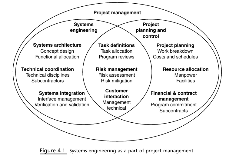
Technical guidance → Systems Engineering (SE).
Financial/contract/program guidance → Project Planning & Control.
Resource allocation & task definition → Shared areas.
Systems Engineers (SE) are responsible for converting stakeholder requirements into technical specifications that can be tested, while project management focuses on handling the project's schedule, cost, contracts, and risks.
Roles in Project & System Management
Program Manager (PM)
Oversees multiple projects to achieve long-term organisational objectives.
Responsible for strategy, portfolio governance, budgets, high-level reporting.
Project Manager
Leads day-to-day execution of a single project: schedules, milestones, staffing, conflict mediation.
Interface between PM, upper management, and technical teams.
Systems Engineer (SE)
Maintains holistic product view; defines, integrates, verifies, validates system against contract.
Advises strategy, conducts technical development, drives integration / test.
4.2 Work Breakdown Structure (WBS)
Hierarchical tree that converts total effort into successively smaller, manageable “work packages”.
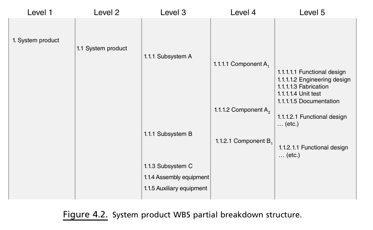
Example (Fig 4.2) shows Subsystem A → Components A1, A2 → design/fab/test work packages at Level 5.
System Support sub-branches: Supply support, Test Equipment, Transport & Handling, Documentation, Facilities, Personnel & Training.
System Testing sub-branches: Integration testing, System testing, Acceptance testing, Operational testsing & evaluation; overarching plan = TEMP (test and evaluation management plan).
Cost Control, Estimating & Critical Path Method (CPM)
WBS lowest-level work packages form cost collection points; another technique to cost control is to identify the value of the work that has been carried out as the project progresses, an approach commonly known as earned value.
Affordability assessment: examine yearly funding, manpower, risk.
Life-cycle cost analysis compares alternatives over acquisition + O&S (Operations and Support) phases.
CPM (Critical Path Method) network:
Nodes = events/milestones, edges = activities (derived from WBS).
Longest-duration path = critical path; non-critical paths have “slack”.
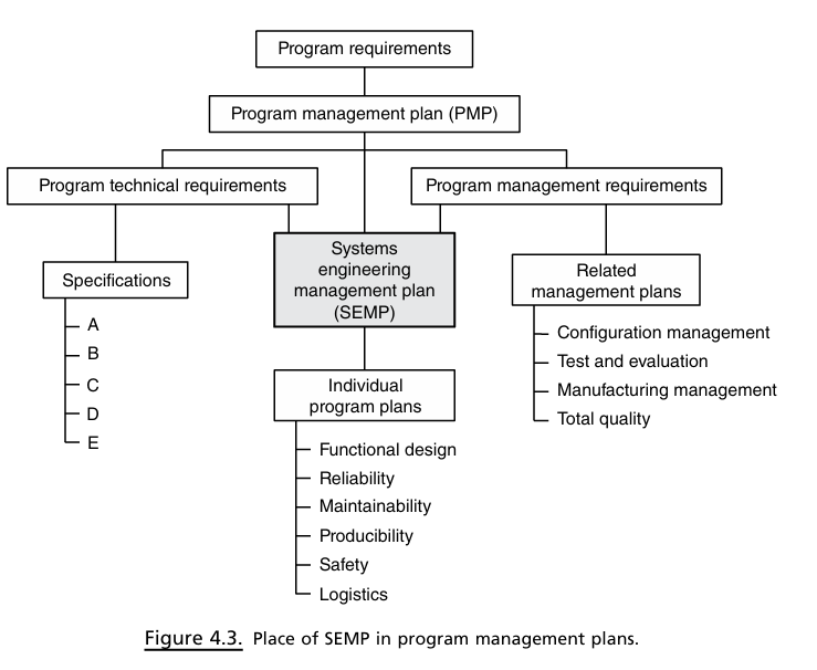
4.3 Systems Engineering Management Plan (SEMP) & SEP
SEP (Systems Engineering Plan) = government (customer) technical plan; approved at each milestone review.
SEMP (Systems Engineering Management Plan) = contractor’s plan for executing SE; “living” document.
Typical SEMP sections:
Program Planning & Control (SOWs (Statements of Work), organization, scheduling, test readiness reviews, risk management).
SE Process (operational requests, functional analysis, system analysis & trade-off strategy, system test & evaluation strategy).
Specialty Integration (RMA (Reliability, maintanability and availability), producibility engineering, safety engineering, human factors engineering, etc.).
4.4 Organisation of Systems Engineering
Prime contractor uses a matrix organization: discipline groups + project IPTs (Integrated Product Teams).
Project SE (often Deputy PM/Associate PM) owns requirements, interfaces, trades, configuration; must foster cross-team communication.
Mechanisms: task assignments (WHAT), schedules/Critical Path (WHEN), requirements/specs (WHY), interface working groups, ICDs, frequent technical meetings.
Systems Analysis Staff: develops models, simulations, trade studies, test data reduction.
System Design Team membership: SE, leads subsystem engineers, support/test/specialty & concurrent engineers, customer representative.
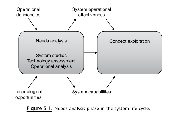
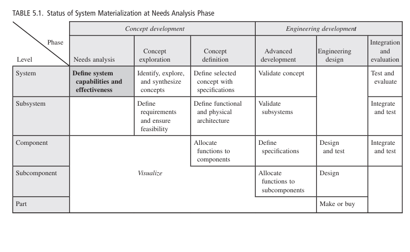
5.1 Needs Analysis Phase (Lifecycle Stage 1)
Objective: demonstrate a valid need/market AND show a feasible, affordable path to satisfy it.
Inputs: Operational deficiencies (needs-driven) OR Technological opportunities (tech-driven).
Outputs: Operational objectives, initial capabilities, feasibility evidence → feed Concept Exploration.
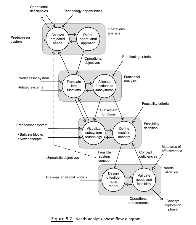
Operations across four SE-method steps:
Operations Analysis → list of operational objectives & capabilities.
Functional Analysis → initial functional requirements.
Feasibility Definition → initial physical requirements & plausible concept.
Needs Validation → MOE (Measures of Effectiveness)-based cost-effectiveness case; produce Initial Capability Document (ICD).
5.2 Systems Thinking
Holistic habit: view system in context of life-cycle, stakeholders, environment, policy, tech trends.
Anticipates emergent behaviour & unintended consequences; designs for robustness & resilience.
Useful perspectives (Kasser & Mackley): operational, functional, big-picture, structural, generic, continuum, temporal, quantitative, scientific.
Tools: Systems dynamics, causal-loop diagrams, agent-based models.
Examples:
Kerala immunisation causal-loops (household trust, media, field workers…).
Advanced Automated Automobile System scenario (sensors, roads, weather, override cases).
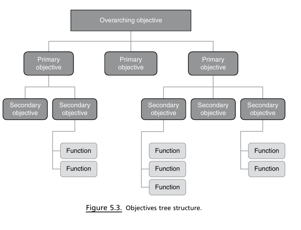
5.3 Operations Analysis & Objectives
Analyse current system deficiencies, threats, competition, tech advances.
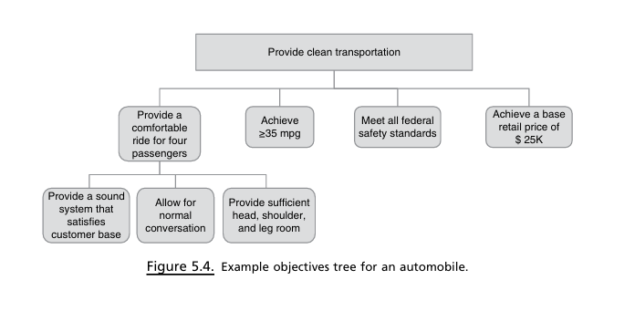
Output = Objectives Tree (Fig 5.3): overarching ⇾ primary ⇾ secondary objectives; stop decomposing when objective becomes verifiable.
Ex: “Provide clean transportation” ⇾ Comfort, Mileage, Safety, Cost (Fig 5.4).
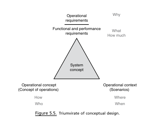
Concept of Operations (CONOPS) & Scenarios
CONOPS = narrative of HOW system will be employed: mission, relationships, information flows, constraints.
Scenarios = specific WHERE/WHEN context; five key elements: mission objectives, friendly parties, threats, environment, sequence/events.
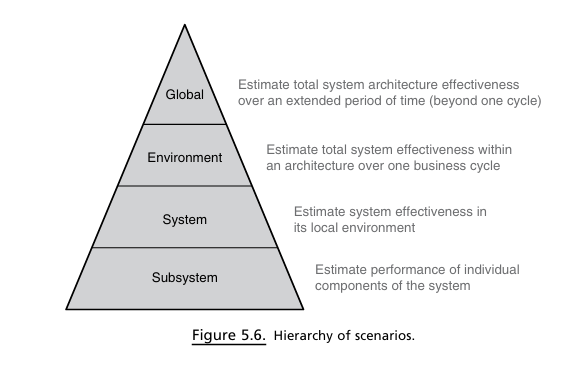
Scenario pyramid: Global ↔ System ↔ Subsystem analyses.
Life-cycle scenarios must include shipping, storage, install, ops, maintenance.
5.4 Feasibility Definition
Visualise subsystem implementation (old vs new vs COTS (Commercial Off-The-Shelf), tech readiness).
Cost analysis: compare with predecessors, include R&D, inflation, risk.
Deliverable: plausible concept + substantiation of feasibility, affordability, risks, development strategy.
5.5 Needs Validation & Effectiveness Analysis
Build operational effectiveness model (analytical/simulation) linking system performance parameters to MOEs.
Define MOEs, test scenarios, validation criteria.
Perform critical experiments or prototyping when new tech is unproven.
Principle: requirements & feasible concept must be considered simultaneously.
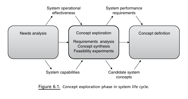
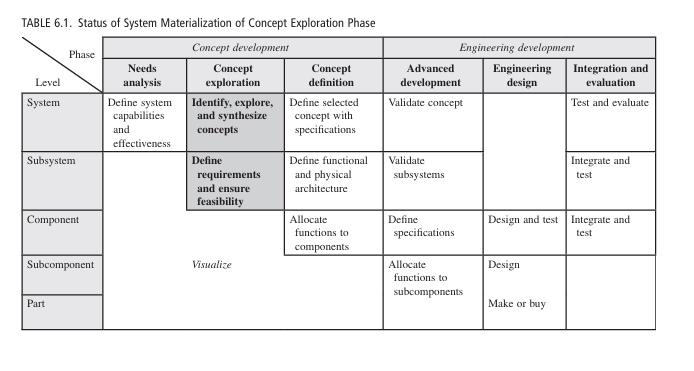
6.1 Requirements Analysis Phase (Concept Exploration)
Converts operational view → engineering view; explores multiple candidate concepts; outputs:
System performance requirements.
Subsystem architecture.
Alternative feasible concepts.
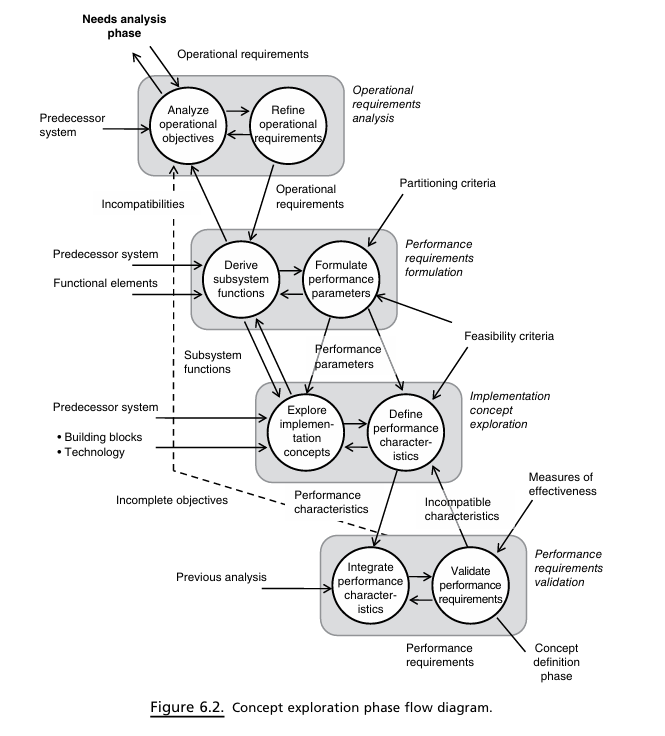
Iterative SE-method steps (Fig 6.2):
Operational Requirements Analysis → complete & consistent.
Performance Requirements Formulation → functions & parameters.
Implementation Concept Exploration → alternative tech/concepts.
Performance Requirements Validation → MOE analysis.
6.2 Requirements Development & Sources
Four typical origins:
Visionary new system for future env/threat.
Improvement of existing system (crowdsourcing feedback).
Threat-driven modification (e.g., new adversary capability).
Additional systems/interoperability (alliances, mergers).
Use extended context diagrams to discover stakeholder, logistics, maintainer, policy interfaces.
6.3 Requirements Features, Attributes, & Metrics
Feature = cohesive set of req’ts satisfying a higher-level objective (e.g., “support travel soccer team”).
SMART attributes: Specific/Simple, Measurable, Attainable, Realistic, Time-bound.
Good requirement example: “System shall transport 20 passengers within 50\,\text{mi} radius.”
Poor requirement pitfalls: vagueness (“all weather”), design solution embedded (“diesel-powered”), vendor specificity.
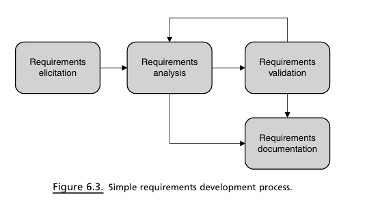
6.4 Requirements Development Process
Elicitation – interviews, studies, SMEs, effectiveness models.
Analysis – tests for traceability, redundancy, consistency, feasibility, affordability, verifiability.
Validation – customer reviews, independent analysis, scenarios.
Documentation – managed in tools (e.g., DOORS); living baseline.
Collective tests: coverage, overall feasibility, system-level verifiability.
6.5 Requirements Hierarchy
Operational Requirements – mission outcomes, stakeholder language.
System-Level Requirements – how whole system performs in environment.
Performance Requirements – engineering characteristics (functions & how well).
Component-Level Requirements & Specifications – detailed technical, design, reliability, interface.
6.6 Requirements Metrics: MOE & MOP
MOE: outcome-oriented, system-level; may be measurement, likelihood, or binary.
MOP: subsystem/attribute performance (feeds MOE).
Example: MOE = max range \text{nm} @ sea-level std day; MOP = engine SFC \frac{\text{lb fuel}}{\text{hp·hr}}.
6.7 Verification & Validation of Requirements
Integration: merge performance characteristics from alternative concepts; ensure necessary & sufficient (no inadvertent bias).
Validation: repeat effectiveness analysis with refined characteristics; confirm satisfies all ops objectives & constraints.
Resulting document should:
State WHAT & HOW WELL, not HOW.
Be verifiable by analysis/test.
Reflect full life-cycle constraints & interfaces.
Living document; updated after each milestone (e.g., SEP/SEMP revisions).
6.8 Traditional vs Agile Requirements Approaches
Traditional SE (waterfall): thorough up-front requirements baseline; strategic, but slower.
Agile/iterative: develop subsets rapidly, continuous stakeholder feedback; tactical, accommodates change, may overlook strategic context if not disciplined.
Key Takeaways & Study Reminders
SE bridges technical and managerial domains; WBS + CPM underpin cost/schedule control.
SEMP/SEP articulate “how SE will be done” & evolve with project.
Needs Analysis asks “WHY a system?”, proves value & feasibility; Systems Thinking ensures holistic view.
Concept Exploration creates performance requirements & candidate concepts; multiple iterations ensure requirements are necessary, sufficient, unbiased.
Requirements must be SMART, traceable, verifiable; organised hierarchically; measured via MOEs & MOPs.
Validation employs effectiveness modelling, scenarios, and critical experiments.
Recognise differences between TSE and Agile methods; pick appropriately for project context.
System: (Airplane)
Engineered
Complex task
Does not need other systems (except infrastructure) to do tis job
Subsystem: (Engine/radar)
Performs significant portion of system functions
Complex functionality
Servers no clear problem-solving function without other subsystems
Component: (Thrust gen/RF front-end)
Single function
Still divisible
Subcomponent: (Reactive nozzles/Amplifier)
Performs elementary function
Not logically divisible into anything except parts
Part: (Seals/transistor)
No significant function except in combination with others
Primitive, indivisible
Scope creep!!!