Topic 3
==3.1 Conceptual Modelling==
- an idea that only exists in mind or possibly on paper
- - A visualization of an idea, often created on paper or through software, in two or three dimensions:
Sketches, Drawings, Flow charts
- - The creation of a smaller or larger tangible version of an object that can be physically interacted with:
Card, Clay, Rapid prototype (3D printing), Balsa wood, Blue styrofoam
- Photorealistic CAD-based interactive models that use surface and solid modelling. They can be considered ‘digital mock-ups’:
Computer-Aided Design (CAD), Surface or Solid modelling, FEA, Data modeling
- is a form of conceptual design which involves the activity of planning and organizing people, infrastructure, communication and material components of a service in order to improve its quality and the interaction between service provider and customers
- is the process of defining the architecture, components, modules, interfaces, and data for a system to satisfy specified requirements
- The process of generating ideas and then developing them into a final product to be sold to consumers
Advantages and Disadvantages of Conceptual Modelling
| Advantages | Disadvantages |
|---|---|
| To help explain features in data setsHelp with project planningPut abstract ideas into a visual understandable form that might not be imaginable otherwisePromote communication between designer, design team members, manufacturer or clientsGauge peoples’ reaction | Make assumptions that which in reality do not work (may lack details – too simplistic, scale may distort perceptions or understandings, materials might reflect the final selection) Graphic models such as flow charts may be difficult for people to understand. |
==3.2 Graphic Modelling==
- is a visualization of an idea, often created on paper or through software. Graphical models are used to communicate with oneself and others which include design team members, the client an the manufacturer. The architect would use plans (orthographic) for the builders but perspective for the client
Examples; diagram, flow chart, rended sketch, conceptual sketch
There can also be 3D graphical Modells often done with CAD
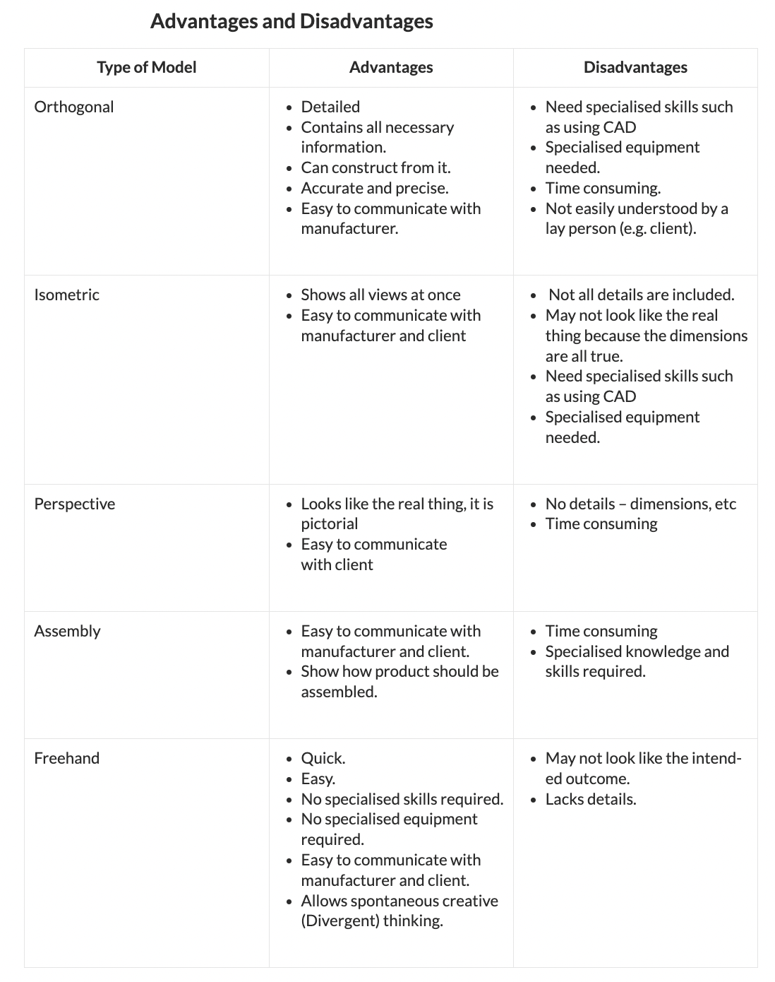
– Systems of drawings that are accurately drawn, the two main types are isometric projection (formal drawing technique) and orthographic projection (working drawing technique).
– Drawings that are bigger or smaller than the real product, but exactly in proportion with product.
– Drawings that are used to guide the production of a product, most commonly orthographical projection, section drawings, part drawings, assembly drawings and plan drawings.
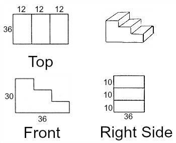
- is a means of representing three-dimensional objects in two dimensions:
- A series of flat (2D) views of an object showing it exactly as it is in shape and size i.e. constructional details.
- An orthographic drawing shows all details and dimensions and is usually used as a production/working drawing.
- It is a convergent thinking style of drawing.
- Orthographic drawings are produced at the final solution stage and are used as working drawings in the realization stage.
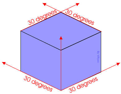
- method for visually representing three-dimensional objects in two dimensions in technical and engineering drawings. It is an axonometric projection in which the three coordinate axes appear equally foreshortened and the angle between any two of them is 120 degrees:
- An isometric drawing depicts the proposed solution in 3D showing shape and form
- They are drawn on a 30/90/30 degree axis
- More on isometric drawings (projections)
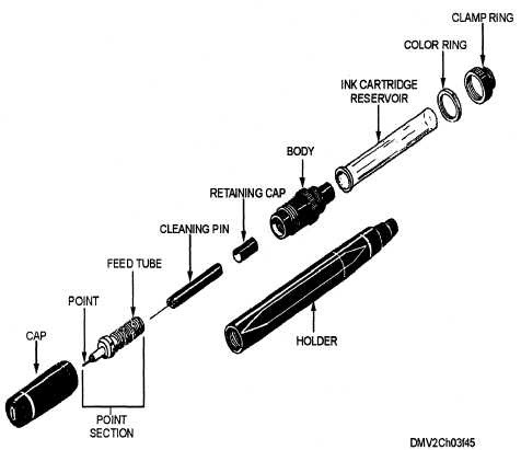
- An isometric drawing of an object with more than one component that depicts how the parts of assemblies fit together.
- The drawing is exploded to show component parts of a product and/or the sequence of assembly.
- Isometric drawings are produced at the final solution stage and are used as working drawings in the realization stage
- A set of formal drawing techniques that depicts an object as getting smaller and closer together the further away they are. The techniques are one-point perspective, two-point perspective, and three-point perspective
– A diagram that shows how components fit together to make a whole
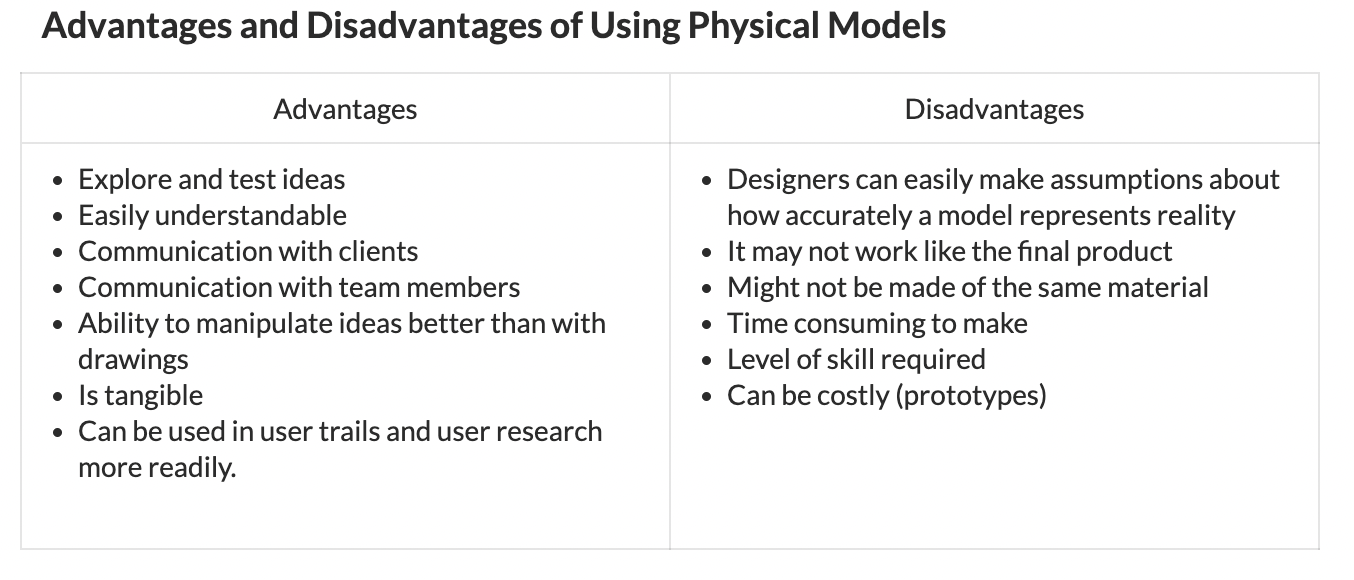
==3.3 Physical Modelling==
- A model that is either a smaller or larger physical copy of an object
- accurate physical representations of objects or features of objects.
- able to allow the design team, client or manufacturer visualise and/or manipulate (examine) the object.
- scaled down or up keeping all sizes of the features in relation to each other.
- A model developed to look and feel like the final product
- An aesethic/appearance prototype or appearance model is as its name suggests.
- It does not function or operate in any way.
- Aesthetic/appearance models are only concerned with form, color, style, texture and how the product fits in its visual environment.
- A scale or full-size representation of a product used to gain feedback from users.
- Mock-ups are used to test ideas and gather feedback from users.
- They can be either full-scale or scaled models of products
- They can have some form of functionality, which means they could be considered a prototype as well.
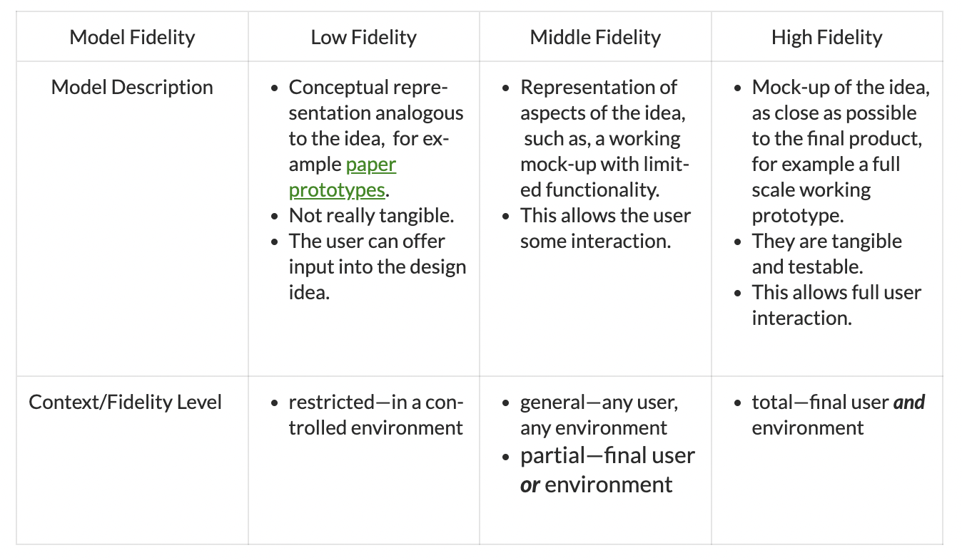
- A sample or model built to test a concept or process, or to act as an object to be replicated or learned from. Prototypes can be developed at a range of fidelity and for different contexts
- Prototypes are to test and evaluate ideas.
- A prototype can be a real working product made to real specifications that can be used throughout design development.
- It has functionality unlike that of a mock-up (minimal) or lack of it in aesthetic models.
- It is particularly useful in testing before production begins.
- Prototypes help the development team discover and issues related to manufacturing the final product.
- It also allows the development team to learn from the user through user feedback and user trials/interaction with the final prototype.
- The degree to which a prototype is exactly like the final product.
- Prototypes that are equipped with the ability to take measurements to provide accurate quantitative feedback for analysis.
- Instrumented physical models are equipped with the ability to take measurements to provide accurate quantitative feedback for analysis.
- They can be used effectively to investigate many phenomena such as fluid flows in hydraulic systems or within wind tunnels, stress within structures and user interaction with a product.
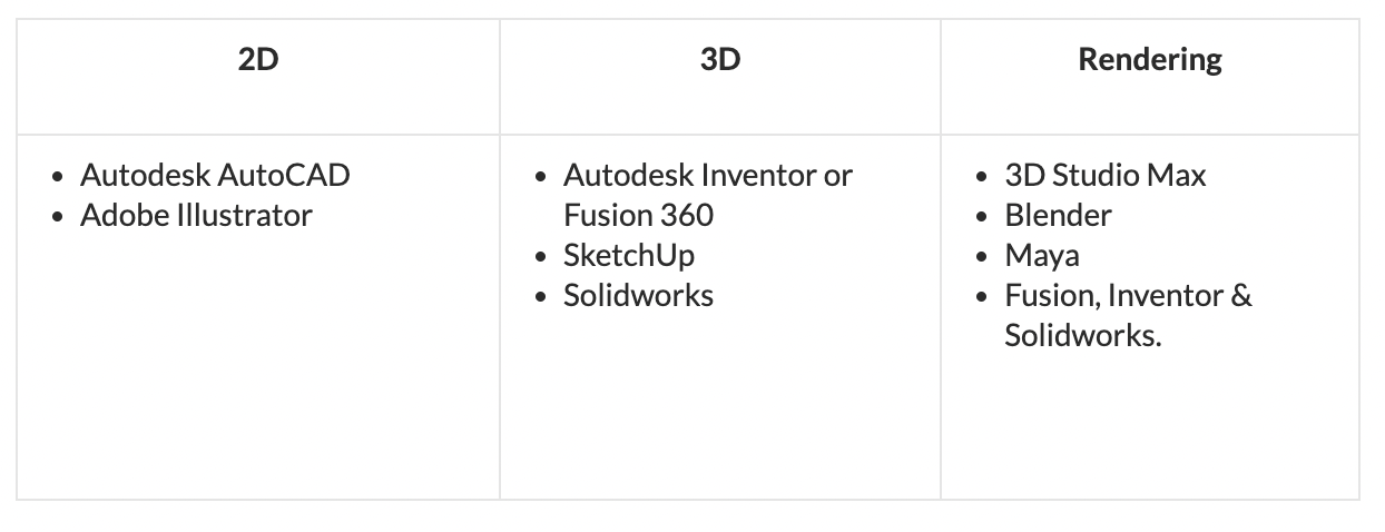
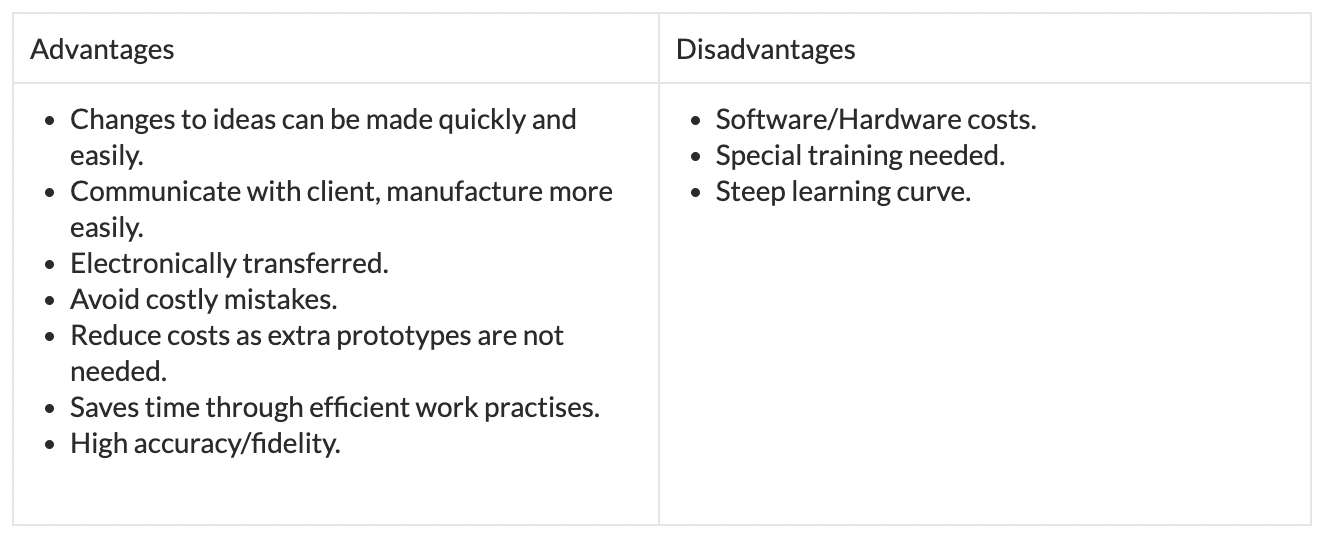
==3.4 Computer Aided Design (CAD)==
– The use of computers to aid the design process
- a particular view of a 3D model that has been converted into a realistic image.
– A realistic picture of the final model, offering some machining data. Surface models contain no data about the interior of the part.
– Solid models are clear representations of the final part. They provide a complete set of data for the product to be realized.
- The main feature of this new method is that the design originates as a concept and gradually evolves into a complete product consisting of components and sub-assemblies
- Once all parts are completed, they are brought together for the first time in the assembly.
- Is a model that determines the structure of data.
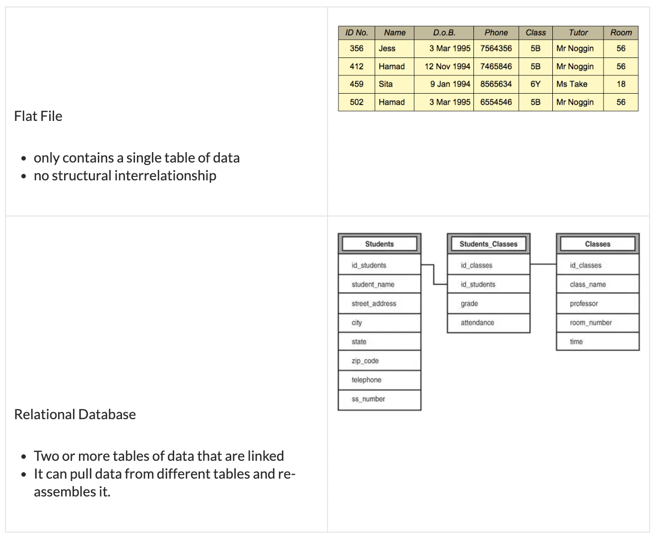
- Photorealistic CAD-based interactive models that use surface and solid modelling. They can be considered ‘digital mock-ups’.
- are computer simulations of the biomechanics of the human body. Help to predict how a human (real) will react in a variety of situation or environments (places or locations).
Haptic technology - is an emerging technology that interfaces the user via the sense of touch.
- How it works is by mechanical actuators apply forces to the user which gives them feedback.
- By simulating the physics of the user’s virtual world, it is possible to compute these forces into real time.
- Haptic technology allows the user to become part of a computer simulation and to interact with it, enabling the designer to observe the user’s performance and to design a better outcome.
- It can be used in different environments particularly ones that are dangerous to humans, remote locations or in difficult locations to train in.
How haptic technology, motion capture, VR and animation can be used to simulate design scenarios and contexts
- Compare animation and virtual reality. – Refer to different design contexts. Consider costs, client needs and development time.
- Describe haptic technology.- * Also known as force feedback technology. Haptic technology works by using mechanical actuators to apply forces to the user. * By simulating the physics of the user’s virtual world, it is possible to compute these forces into real time.
- Explain how haptic technology and motion capture have enhanced design capability.- * Haptic technology allows the user to become part of a computer simulation and to interact with it, enabling the designer to observe the user’s performance, so as to design a better outcome. * Haptic technology can also be used in situations where it may prove difficult to train in the real environment. * Haptic technology is also used in feedback devices used in home entertainment consoles. * Motion capturing a number of users’ movements will allow designers to design better ergonomic products. * Motion capture allows the designer to understand the users’ physiological requirements.
- The calculation and simulation of unknown factors in products using CAD systems. For example, simulating the stresses within a welded car part.
==3.5 Rapid Prototyping==
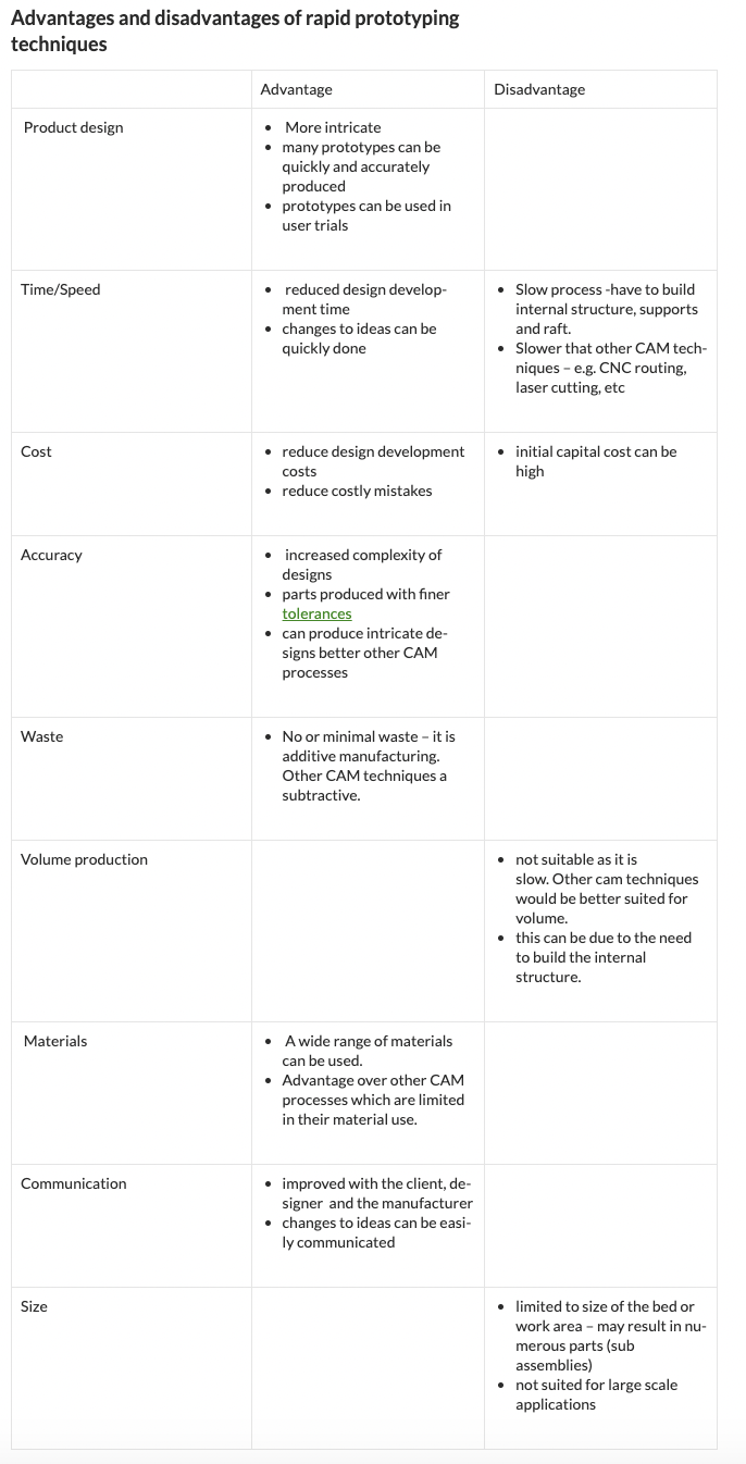
- the fast fabrication of a physical part, model or assembly using 3D computer aided design (CAD). The creation of the part, model or assembly is usually completed using additive manufacturing, or more commonly known as 3D printing
- entails a machine that produces a complete product including internal details, at a fairly quick rate.
- reduce product development time as prototypes are quickly made and can be tested
The Process:
- Using CAD software produce a full scale model
- Export or convert model in STL (Standard Triangle Language and Standard Tessellation Language).
- send to RP machine
- manufacture the item
- clean up the item
(SLA) is a 3D printing process
- that uses a vat of photosensitive resin and a vertically moving platform.
- It uses a laser beam, directed onto the surface of the photosensitive resin, to print the pattern of the current model layer by hardening the photosensitive resin.
- The platform then moves down by a layer thickness so the next layer can be printed*.*
- Also known as optical fabrication, photo-solidification, solid free-form fabrication and solid imaging.
- LOM machines take the sliced CAD data from the 3D model and cut out each layer from a roll of material, using a laser or plotter cutter. These sliced layers are glued together to form the model, which is either built on a movable platform below the machine or on pins when using card. (IB TSM 2015)
- A rapid prototyping systems that creates a 3D product by manufacture (LOM) converting it into slices, cutting the slices out and joining the slices together
An FDM machine is
- A heated extrusion nozzle (extruder) that moves through the x & y axis
- A plastic (such as ABS, PLA), metal or composite (such as30% metal, bamboo, etc fill PLA) filament is fed through he extruder
- basically a CNC robot that holds a small extrusion head. The extrusion head moves back and forth along a platform, building up a 3D model by feeding heated plastic wire through the extrusion head.
- Either the platform or extruder move through the Z axis place a layer if build material
- Controlled by CAM software.
SLS is a 3D printing process based on sintering.
- A high powered CO2 laser is used to sinter a thin layer of heat-fusible powder that gradually builds up the 3D model.
- Powders include, plastic, metal, ceramics and glass
\