
physics topic 6 (waves)
Types of waves
Waves are one of the ways in which energy may be transferred between stores. Waves can be described as oscillations, or vibrations about a rest position. For example:
sound waves cause air particles to vibrate back and forth
ripples cause water particles to vibrate up and down
The direction of these oscillations is the difference between longitudinal or transverse waves. In longitudinal waves, the vibrations are parallel to the direction of wave travel. In transverse waves, the vibrations are at right angles to the direction of wave travel.
Mechanical waves cause oscillations of particles in a solid, liquid or gas and must have a medium to travel through. Electromagnetic waves cause oscillations in electrical and magnetic fields.
Key fact
All waves transfer energy but they do not transfer matter.
Parts of a wave
Waves are described using the following terms:
rest position - the undisturbed position of particles or fields when they are not vibrating
displacement - the distance that a certain point in the medium has moved from its rest position
peak - the highest point above the rest position
trough - the lowest point below the rest position
amplitude - the maximum displacement of a point of a wave from its rest position.
wavelength - distance covered by a full cycle of the wave, usually measured from peak to peak, or trough to trough
time period - the time taken for a full cycle of the wave, usually measured from peak to peak, or trough to trough
frequency - the number of waves passing a point each second
Diagram of a wave
The time period of a wave can be calculated using the equation:
time period = 1/frequency.
The speed of a wave can be calculated using the equation: wave speed = frequency × wavelength.
Measuring the speed of sound in air
The air is made up of many tiny particles. When sound is created, the air particles vibrate and collide with each other, causing the vibrations to pass between air particles. The vibrating particles pass the sound through to a person's ear and vibrate the ear drum.
Light travels much faster than sound through air. For example, a person fires a starting pistol and raises their hand in the air at the same time. A distant observer stood 400 metres (m) away records the time between seeing the action (the light reaches the time keeper immediately) and hearing the sound (which takes more time to cover the same distance).
The speed of sound can be calculated using the equation:
speed = distance/time
This is when:
speed (v) is measured in metres per second (m/s)
distance (s) is measured in metres (m)
time (t) is measured in seconds (s)
Required practical - measuring waves in a ripple tank
Measure the frequency, wavelength and speed of waves in a ripple tank
A ripple tank can be used to measure and calculate frequency, wavelength and the speed of waves on the surface of the water. A ripple tank is a transparent shallow tray of water with a light shining down through it onto a white card below in order to clearly see the motion of the ripples created on the water’s surface. Ripples can be made by hand but to generate regular ripples it is better to use a motor.
Aim of the experiment
To measure the frequency, wavelength and speed of waves in a ripple tank.
Method
Set up the ripple tank as shown in the diagram with about 5 cm depth of water.
Adjust the height of the wooden rod so that it just touches the surface of the water.
Switch on the lamp and motor and adjust until low frequency waves can be clearly observed.
Measure the length of a number of waves then divide by the number of waves to record wavelength. It may be more practical to take a photograph of the card with the ruler and take measurements from the still picture.
Count the number of waves passing a point in ten seconds then divide by ten to record frequency.
Calculate the speed of the waves using: wave speed = frequency × wavelength.
Required practical - measuring waves in a solid
Measure the frequency, wavelength and speed of waves in a solid
To measure the frequency, wavelength and speed of waves in a string.
Method
Attach a string or cord to a vibration generator and use a 200 gram (g) hanging mass and pulley to pull the string taut as shown in the diagram. Place a wooden bridge under the string near the pulley.
Switch on the vibration generator and adjust the wooden bridge until stationary waves can be clearly observed.
Measure the length of as many half wavelengths (loops) as possible, divide by the number of half wavelengths (loops). This is half the wavelength, doubling this gives the wavelength.
The frequency is the frequency of the power supply.
Calculate the speed of the waves using: wave speed = frequency × wavelength.
Longitudinal waves
In longitudinal waves, the vibrations are parallel to the direction of wave travel.
Examples of longitudinal waves include:
sound waves
ultrasound waves
seismic P-waves
One way to remember the movement of particles in longitudinal waves is to use the 'P' sound: longitudinal waves such as seismic P-waves may be thought of as pressure or push waves as the particles move parallel to the wave.
Demonstrating longitudinal waves
Longitudinal waves show areas of compression and rarefaction:
compressions are regions of high pressure due to particles being close together
rarefactions are regions of low pressure due to particles being spread further apart
Longitudinal waves are often demonstrated by pushing and pulling a stretched slinky spring.
Transverse waves
In transverse waves, the vibrations are at right angles to the direction of wave travel.
Examples of transverse waves include:
ripples on the surface of water
vibrations in a guitar string
a Mexican wave in a sports stadium
electromagnetic waves - eg light waves, microwaves, radio waves
seismic S-waves
One way to remember the movement of particles in transverse waves is to use the 'S' sound: transverse waves such as seismic S-waves may be thought of as shake or shear waves as the particles move from side-to-side - crossing the direction of wave travel.
Demonstrating transverse waves
Transverse waves are often demonstrated by moving a rope rapidly up and down.
Electromagnetic waves
Electromagnetic waves are transverse waves. Their vibrations or oscillations are changes in electrical and magnetic fields at right angles to the direction of wave travel.
All electromagnetic waves:
transfer energy as radiation from the source of the waves to an absorber
can travel through a vacuum such as in space
travel at the same speed through a vacuum or the air
Electromagnetic waves travel at 300 million metres per second (m/s) through a vacuum.
Electromagnetic spectrum
Electromagnetic waves form a continuous spectrum of waves. This includes:
waves with a very short wavelength, high frequency and high energy
waves with a very long wavelength, low frequency and low energy
Electromagnetic waves can be separated into seven distinct groups in the spectrum.
Radio waves, microwaves, infrared and visible light
The behaviour of an electromagnetic wave in a substance depends on its frequency. The differing behaviours of different groups in the electromagnetic spectrum make them suitable for a range of uses.
Radio waves
Radio waves are used for communication such as television and radio.
Figure caption,
The electromagnetic spectrum
Radio waves - Higher
Radio waves are transmitted easily through air. They do not cause damage if absorbed by the human body, and they can be reflected to change their direction. These properties make them ideal for communications.
Radio waves can be produced by oscillations in electrical circuits. When radio waves are absorbed by a conductor, they create an alternating current. This electrical current has the same frequency as the radio waves. Information is coded into the wave before transmission, which can then be decoded when the wave is received. Television and radio systems use this principle to broadcast information.
Microwaves
Microwaves are used for cooking food and for satellite communications.
Microwaves - Higher
High frequency microwaves have frequencies which are easily absorbed by molecules in food. The internal energy of the molecules increases when they absorb microwaves, which causes heating. Microwaves pass easily through the atmosphere, so they can pass between stations on Earth and satellites in orbit.
Infrared
Infrared light is used by electrical heaters, cookers for cooking food, and by infrared cameras which detect people in the dark.
Infrared - Higher
Infrared light has frequencies which are absorbed by some chemical bonds. The internal energy of the bonds increases when they absorb infrared light, which causes heating. This makes infrared light useful for electrical heaters and for cooking food. All objects emit infrared light. The human eye cannot see this light but infrared cameras can detect it. This 'thermal imaging' is useful for detecting people in the dark.
Visible light
Visible light is the light we can see. It is used in fibre optic communications, where coded pulses of light travel through glass fibres from a source to a receiver.
Ultraviolet, EM waves in medicine and ionising radiation
Ultraviolet
We cannot see ultraviolet light but it can have hazardous effects on the human body. Ultraviolet light in sunlight can cause the skin to tan or burn. Fluorescent substances are used in energy-efficient lamps - they absorb ultraviolet light produced inside the lamp, and re-emit the energy as visible light.
Electromagnetic waves in medicine
Changes in atoms and their nuclei can cause electromagnetic waves to be generated or absorbed. Gamma rays are produced by changes in the nucleus of an atom. They are a form of nuclear radiation. High energy waves such as X-rays and gamma rays are transmitted through body tissues with very little absorption. This makes them ideal for internal imaging. X-rays are absorbed by dense structures like bones, which is why X-ray photos are used to help identify broken bones.
Ionising radiation
Ultraviolet waves, X-rays and gamma rays are types of ionising radiation. They can add or remove electrons from molecules, producing electrically charged ions. Ionisation can have hazardous effects on the body:
ultraviolet waves can cause skin to age prematurely and increase the risk of skin cancer
x-rays and gamma rays can cause the mutation of genes, which can lead to cancer
Radiation dose
Radiation dose is a measure of the risk of harm caused by exposing the body to ionising radiation. Radiation dose is measured in Sieverts (Sv). As radiation dose figures are generally small, they are usually given in millisieverts (mSv):
1000 mSv = 1 Sv
Background radiation is all around us, all the time. Sources include:
radioactive rocks in the Earth's crust
cosmic rays from space
man-made sources such as nuclear weapons fallout and nuclear accidents
The level of background radiation and dose are affected by factors such as the jobs that people do and the places where people live.
Reflection of waves
Waves - including sound and light - can be reflected at the boundary between two different materials. The reflection of sound causes echoes.
The law of reflection states that:
angle of incidence = angle of reflection
For example, if a light ray hits a surface at 32°, it will be reflected at 32°.
The angles of incidence and reflection are measured between the light ray and the normal - an imaginary line at 90° to the surface. The diagrams show a water wave being reflected at a barrier, and a light ray being reflected at a plane mirror.
Specular reflection
Reflection from a smooth, flat surface is called specular reflection. This is the type of reflection that happens with a flat mirror. The image in a mirror is:
upright
virtual
In a virtual image, the rays appear to diverge from behind the mirror, so the image appears to come from behind the mirror.
Figure caption,
A ray diagram showing how an image forms in a plane mirror
Diffuse reflection
If a surface is rough, diffuse reflection happens. Instead of forming an image, the reflected light is scattered in all directions. This may cause a distorted image of the object, as occurs with rippling water, or no image at all. Each individual reflection still obeys the law of reflection, but the different parts of the rough surface are at different angles.
Refraction of waves
Different materials have different densities. Light waves may change direction at the boundary between two transparent materials. Refraction is the change in direction of a wave at such a boundary.
It is important to be able to draw ray diagrams to show the refraction of a wave at a boundary.
Figure caption,
A ray diagram showing refraction at the boundary between air and glass
Refraction can cause optical illusions as the light waves appear to come from a different position to their actual source.
Explaining refraction - Higher
The density of a material affects the speed that a wave will be transmitted through it. In general, the denser the transparent material, the more slowly light travels through it.
Glass is denser than air, so a light ray passing from air into glass slows down. If the ray meets the boundary at an angle to the normal, it bends towards the normal.
The reverse is also true. A light ray speeds up as it passes from glass into air, and bends away from the normal by the same angle.
Image gallerySkip image gallery
1
Slide 1 of 3, Light ray hits glass block at right angles to surface. Wave slows, its wavelength decreases as it enters glass. As wave returns to air, speed and wavelength increase to original values.,
End of image gallery
Key fact
A useful way of remembering the speed and direction changes of light during refraction is ‘FAST’: Faster - Away / Slower - Towards.
Wave speed, frequency and wavelength in refraction
For a given frequency of light, the wavelength is proportional to the wave speed:
wave speed = frequency × wavelength
So if a wave slows down, its wavelength will decrease. The effect of this can be shown using wave front diagrams like the one below. The diagram shows that as a wave travels into a denser medium, such as water, it slows down and the wavelength decreases. Although the wave slows down, its frequency remains the same, due to the fact that its wavelength is shorter.
Required practical
Investigate the reflection of light by different types of surface and the refraction of light by different substances
Aim of the experiment
To investigate the reflection of light by different types of surface, and the refraction of light by different substances.
Method
Set up a ray box, slit and lens so that a narrow ray of light is produced.
Place a 30 centimetre (cm) ruler near the middle of a piece of plain A3 paper. Draw a straight line parallel to its longer sides. Use a protractor to draw a second line at right angles to this line. Label this line with an ‘N’ for ‘normal’.
Place the longest side of a rectangular acrylic polymer block against the first line. With the normal near the middle of the block, carefully draw around the block without moving it.
Use the ray box to shine a ray of light at the point where the normal meets the block. This is the incident ray.
The angle between the normal and the incident ray is called the angle of incidence. Move the ray box or paper to change the angle of incidence. The aim is to see a clear ray reflected from the surface of the block and another clear ray leaving the opposite face of the block.
Using a pencil on the paper, mark the path of:
the incident ray with a cross
the reflected ray with a cross
the ray that leaves the block with two crosses - one near the block and the other further away
Remove the block. Join the crosses to show the paths of the light rays.
Repeat steps 2 to 7 for a rectangular glass block.
Measure the angle of incidence, angle of refraction and angle of reflection for each block.
Sound waves
Sound waves are longitudinal waves. They cause particles to vibrate parallel to the direction of wave travel. The vibrations can travel through solids, liquids or gases. The speed of sound depends on the medium through which it is travelling. When travelling through air, the speed of sound is about 330 metres per second (m/s). Sound cannot travel through a vacuum because there are no particles to carry the vibrations.
The ear
The human ear detects sound. Sound waves enter the ear canal and cause the eardrum to vibrate. Three small bones transmit these vibrations to the cochlea. This produces electrical signals which pass through the auditory nerve to the brain, where they are interpreted as sound.
Properties of sound
The frequency of a sound wave is related to the pitch that is heard:
high frequency sound waves are high pitched
low frequency sound waves are low pitched
The amplitude of a sound wave is related to the volume of the sound:
high amplitude sound waves are loud
low amplitude sound waves are quiet
Oscilloscope traces showing the following sounds:
quiet, low pitch sound
loud, low pitch sound
loud, high pitch sound
The cochlea is only stimulated by a limited range of frequencies. This means that humans can only hear certain frequencies. The range of normal human hearing is 20 Hertz (Hz) to 20,000 Hz (20 kHz).
Ultrasound
Ultrasound waves have a frequency higher than the upper limit for human hearing - above 20,000 Hertz (Hz). Different species of animal have different hearing ranges. This explains why a dog can hear the ultrasound produced by a dog whistle but humans cannot.
Uses of ultrasound
Uses of ultrasound include:
breaking kidney stones
cleaning jewellery
In both of these applications, the vibrations caused by the ultrasound shake apart the dirt or kidney stones, breaking them up. The principle is the same as the opera singer's trick, where a glass may shatter if the singer makes a high-pitched sound near to the glass.
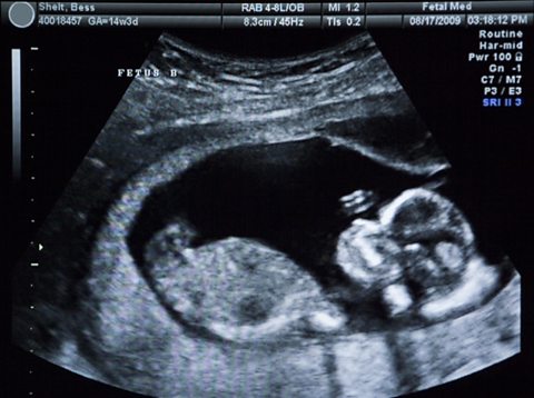
Ultrasound imaging creates a picture of something that cannot be seen directly, such as an unborn baby in the womb, or faults and defects inside manufactured parts.
These uses rely on what happens when ultrasound waves meet the boundary between two different materials. When this happens:
some of the ultrasound waves are reflected at the boundary
the time taken for the waves to leave a source and return to a detector is measured
the depth of the boundary can be determined using the speed of sound in the material and the time taken
Echo sounding
High frequency sound waves can be used to detect objects in deep water and to measure water depth. The time between a pulse of sound being transmitted and detected and the speed of sound in water can be used to calculate the distance of the reflecting surface or object. The process is very similar to ultrasound imaging. However, the sound waves used are within normal hearing range, and they are used to identify objects rather than internal structures.
This technique is applied in sonar systems used to find shipwrecks, submarines and shoals of fish. Bats and dolphins use a similar method called 'echolocation' to detect their surroundings and to find food.
Seismic waves
Seismic waves are produced by earthquakes in the Earth’s crust. They can cause damage to structures on the Earth’s surface, as well as tsunamis.
Figure caption,
The structure of the Earth
Properties of seismic waves
There are two types of seismic waves:
P-waves, which are longitudinal waves
S-waves, which are transverse waves
P-waves and S-waves have different properties. The table summarises these properties.
P-waves | S-waves | |
Type of wave | longitudinal | transverse |
Relative speed | faster | slower |
Can travel through | solids and liquids | solids only |
Investigating Earth structure using seismic waves
The study of seismic waves provides evidence for the internal structure of the Earth, which otherwise cannot be observed directly.
Seismic waves from large earthquakes are detected around the world. Their paths are curved as the waves refract due to the gradually changing density of the layers.
S-waves are not detected on the opposite side of the Earth - this suggests that the mantle has solid properties, but the outer core must be liquid.
P-waves are detected on the opposite side of the Earth. Refractions between layers cause two shadow zones where no P-waves are detected. The size and positions of these shadow zones indicate there is a solid inner core.
Convex and concave lenses
A lens is a shaped piece of transparent glass or plastic that refracts light. When light is refracted it changes direction due to the change in density as it moves from air into glass or plastic. Lenses are used in cameras, telescopes, binoculars, microscopes and corrective glasses. A lens can be convex or concave.
Convex lenses
A convex lens is thicker in the middle than it is at the edges. Parallel light rays that enter the lens converge. They come together at a point called the principal focus.
In a ray diagram, a convex lens is drawn as a vertical line with outward facing arrows to indicate the shape of the lens. The distance from the lens to the principal focus is called the focal length.
Concave lenses
A concave lens is thinner in the middle than it is at the edges. This causes parallel rays to diverge. They separate but appear to come from a principle focus on the other side of the lens.
In a ray diagram, a concave lens is drawn as a vertical line with inward facing arrows to indicate the shape of the lens.
Real and virtual images
The images formed by a lens can be:
upright or inverted (upside down compared to the object)
magnified or diminished (smaller than the object)
real or virtual
A real image is an image that can be projected onto a screen. A virtual image appears to come from behind the lens.
To draw a ray diagram:
Draw a ray from the object to the lens that is parallel to the principal axis. Once through the lens, the ray should pass through the principal focus.
Draw a ray which passes from the object through the centre of the lens.
Some ray diagrams may also show a third ray.
Convex lenses
The type of image formed by a convex lens depends on the lens used and the distance from the object to the lens.
A camera or human eye
Cameras and eyes contain convex lenses. For a distant object that is placed more than twice the focal length from the lens, the image is:
inverted
diminished
real
Figure caption,
Ray diagram for an object placed more than two focal lengths away from a convex lens
Projectors
Projectors contain convex lenses. For an object placed between one and two focal lengths from the lens, the image is:
inverted
magnified
real
Figure caption,
Ray diagram for an object placed between 2F and F from a convex lens
In a film or data projector, this image is formed on a screen. Film must be loaded into the projector upside down so the projected image is the right way up.
Magnifying glasses
A magnifying glass is a convex lens used to make an object appear much larger than it actually is. This works when the object is placed at a distance less than the focal length. The image is:
upright
magnified
virtual
Figure caption,
Ray diagram for an object placed less than one focal length from a convex lens
Only the person using the magnifying glass can see the image. The image cannot be projected onto a screen because it is a virtual image.
Concave lenses
Concave lenses always produce images that are:
upright
diminished
virtual
Peep hole lenses
Peep holes are set into doors so the occupant can identify a visitor before opening the door.
Figure caption,
Ray diagram for an object viewed through a concave lens
For an object viewed through a concave lens, light rays from the top of the object will be refracted and will diverge on the other side of the lens. These rays will appear:
from the same side of the principal axis meaning the image will be upright
further from the principal axis, so the image will be smaller than the object
Magnification
Magnification is a measure of the size of an image compared to the size of the object. Lenses and curved mirrors can produce magnified images.
Calculating magnification
The magnification produced by a lens can be calculated using the equation:
magnification = image/actual
Magnification is a ratio of two lengths, so it has no units. However, the image height and object height should both be measured in the same units, eg centimetres (cm) or millimetres (mm), but not a mixture of the two.
Colour
Within the visible light range of the electromagnetic spectrum there is a spectrum of colour. This is a continuous range of colours. In order of increasing frequency and decreasing wavelength these are given as:
red
orange
yellow
green
blue
indigo
violet
Each colour within the visible light spectrum has its own narrow band of wavelength and frequency.
Absorption of light
Waves can be absorbed at the boundary between two different materials. When waves are absorbed by a surface, the energy of the wave is transferred to the particles in the surface. This will usually increase the internal energy of the particles.
When white light shines on an opaque object, some wavelengths or colours of light are absorbed. These wavelengths are not detected by our eyes. The other wavelengths are reflected, and these are detected by our eyes.
For example, grass appears green in white light:
red, orange, yellow, blue, indigo and violet are absorbed by the grass
green light is reflected by the grass and detected by our eyes
Transmission of light
Waves can also be transmitted at the boundary between two different materials. When waves are transmitted, the wave continues through the material. Air, glass and water are common materials that are very good at transmitting light. They are transparent because light is transmitted with very little absorption. Translucent materials transmit some light but are not completely clear. Lamp shades, shower curtains and window blinds are often translucent objects.
Colour filters
When white light passes through a coloured filter, all colours are absorbed except for the colour of the filter. For example, an orange filter transmits orange light but absorbs all the other colours. If white light is shone on an orange filter, only the orange wavelengths will be observed by the human eye.
Coloured objects in coloured light
An object appears to be black if it absorbs all the wavelengths of visible light. For example, an object that appears blue in white light will appear black in red light. This is because the red light contains no blue light for the object to reflect.
Emission and absorption of infrared radiation
All bodies (objects) emit and absorb infrared radiation. They do this whatever their temperature. The hotter the body:
the more infrared radiation it gives out in a given time
the greater the proportion of emitted radiation is visible light
Black bodies
There are no known objects that are perfect at absorbing or emitting all the radiation, of every possible frequency, that may be directed at it. Some objects do, however, come close to this and these are referred to as "black bodies".
A perfect black body is a theoretical object. It would have these properties:
it would absorb all the radiation that falls on it
it would not reflect or transmit any radiation
An object that is good at absorbing radiation is also a good emitter, so a perfect black body would be the best possible emitter of radiation.
Figure caption,
Features of a perfect black body
Stars are considered to be black bodies because they are very good emitters of most wavelengths in the electromagnetic spectrum. This suggests that stars also absorb most wavelengths. Whilst there are a few wavelengths that stars do not absorb or emit, this figure is very low, so they can be treated as black bodies. Planets and black holes are also treated as nearly perfect black bodies.
Poor absorbers and emitters
White and shiny silvery surfaces are the worst absorbers, as they reflect all visible light wavelengths. Poor absorbers are also poor emitters, and do not emit radiation as quickly as darker colours. Radiators in homes are usually painted white so that the infrared radiation is emitted gradually.
Required practical
Investigate how the amount of infrared radiation absorbed or radiated by a surface depends on the nature of that surface
There are different ways to investigate the amount of infrared radiation absorbed or radiated by a surface. It is important to:
use appropriate apparatus to measure and record temperature accurately
make observations regarding the effects of electromagnetic waves on different substances
The method described here uses a Leslie cube. This is a metal cube with four different types of surface. It is filled with hot water to increase its temperature.
Aim of the experiment
To investigate how the amount of infrared radiation absorbed or radiated by a surface depends on the nature of that surface.
Method
Place a Leslie cube on a heat-resistant mat. Fill it, almost to the top, with boiling water and replace the lid.
Leave for one minute. This is to enable the surfaces to heat up to the temperature of the water.
Use the infrared detector to measure the intensity of infrared radiation emitted from each surface, or the temperature of the surface. Make sure that the detector is the same distance from each surface for each reading.
The Earth's temperature - Higher
The temperature of a body is linked to the balance between the amount of radiation absorbed and emitted.
Rate of absorption | Temperature of the body |
Greater than the rate of emission | Increasing |
Equal to the rate of emission | Constant |
Less than the rate of emission | Decreasing |
Factors affecting the Earth’s temperature
The temperature of the Earth depends on many factors including the concentration of greenhouse gases such as water vapour, methane and carbon dioxide.
The Earth’s temperature also depends on the rates at which light radiation and infrared radiation are:
absorbed by the Earth’s surface and atmosphere
emitted by the Earth’s surface and atmosphere
When visible light and high frequency infrared radiation are absorbed by the surface of the Earth, the planet’s internal energy increases and the surface gets hotter. Some of this energy is transferred to the atmosphere by conduction and convection.
The Earth also radiates lower frequency infrared radiation. Some of this infrared radiation is transmitted through the atmosphere back out into space, and some is absorbed by greenhouse gases in the atmosphere. The greenhouse gases emit infrared radiation in all directions - some out into space and some back towards Earth, which is then reabsorbed.
The greenhouse effect
The ‘greenhouse effect’ caused by naturally occurring greenhouse gases, such as water vapour, stabilises the surface temperature of Earth. This allows the planet to support life.
However, human activities such as deforestation and the burning of fossil fuels are releasing additional carbon dioxide. This causes more infrared radiation to be ‘trapped’ and reabsorbed by the Earth’s surface. This enhanced greenhouse effect is causing global temperatures to increase, leading to climate change.
physics topic 6 (waves)
Types of waves
Waves are one of the ways in which energy may be transferred between stores. Waves can be described as oscillations, or vibrations about a rest position. For example:
sound waves cause air particles to vibrate back and forth
ripples cause water particles to vibrate up and down
The direction of these oscillations is the difference between longitudinal or transverse waves. In longitudinal waves, the vibrations are parallel to the direction of wave travel. In transverse waves, the vibrations are at right angles to the direction of wave travel.
Mechanical waves cause oscillations of particles in a solid, liquid or gas and must have a medium to travel through. Electromagnetic waves cause oscillations in electrical and magnetic fields.
Key fact
All waves transfer energy but they do not transfer matter.
Parts of a wave
Waves are described using the following terms:
rest position - the undisturbed position of particles or fields when they are not vibrating
displacement - the distance that a certain point in the medium has moved from its rest position
peak - the highest point above the rest position
trough - the lowest point below the rest position
amplitude - the maximum displacement of a point of a wave from its rest position.
wavelength - distance covered by a full cycle of the wave, usually measured from peak to peak, or trough to trough
time period - the time taken for a full cycle of the wave, usually measured from peak to peak, or trough to trough
frequency - the number of waves passing a point each second
Diagram of a wave
The time period of a wave can be calculated using the equation:
time period = 1/frequency.
The speed of a wave can be calculated using the equation: wave speed = frequency × wavelength.
Measuring the speed of sound in air
The air is made up of many tiny particles. When sound is created, the air particles vibrate and collide with each other, causing the vibrations to pass between air particles. The vibrating particles pass the sound through to a person's ear and vibrate the ear drum.
Light travels much faster than sound through air. For example, a person fires a starting pistol and raises their hand in the air at the same time. A distant observer stood 400 metres (m) away records the time between seeing the action (the light reaches the time keeper immediately) and hearing the sound (which takes more time to cover the same distance).
The speed of sound can be calculated using the equation:
speed = distance/time
This is when:
speed (v) is measured in metres per second (m/s)
distance (s) is measured in metres (m)
time (t) is measured in seconds (s)
Required practical - measuring waves in a ripple tank
Measure the frequency, wavelength and speed of waves in a ripple tank
A ripple tank can be used to measure and calculate frequency, wavelength and the speed of waves on the surface of the water. A ripple tank is a transparent shallow tray of water with a light shining down through it onto a white card below in order to clearly see the motion of the ripples created on the water’s surface. Ripples can be made by hand but to generate regular ripples it is better to use a motor.
Aim of the experiment
To measure the frequency, wavelength and speed of waves in a ripple tank.
Method
Set up the ripple tank as shown in the diagram with about 5 cm depth of water.
Adjust the height of the wooden rod so that it just touches the surface of the water.
Switch on the lamp and motor and adjust until low frequency waves can be clearly observed.
Measure the length of a number of waves then divide by the number of waves to record wavelength. It may be more practical to take a photograph of the card with the ruler and take measurements from the still picture.
Count the number of waves passing a point in ten seconds then divide by ten to record frequency.
Calculate the speed of the waves using: wave speed = frequency × wavelength.
Required practical - measuring waves in a solid
Measure the frequency, wavelength and speed of waves in a solid
To measure the frequency, wavelength and speed of waves in a string.
Method
Attach a string or cord to a vibration generator and use a 200 gram (g) hanging mass and pulley to pull the string taut as shown in the diagram. Place a wooden bridge under the string near the pulley.
Switch on the vibration generator and adjust the wooden bridge until stationary waves can be clearly observed.
Measure the length of as many half wavelengths (loops) as possible, divide by the number of half wavelengths (loops). This is half the wavelength, doubling this gives the wavelength.
The frequency is the frequency of the power supply.
Calculate the speed of the waves using: wave speed = frequency × wavelength.
Longitudinal waves
In longitudinal waves, the vibrations are parallel to the direction of wave travel.
Examples of longitudinal waves include:
sound waves
ultrasound waves
seismic P-waves
One way to remember the movement of particles in longitudinal waves is to use the 'P' sound: longitudinal waves such as seismic P-waves may be thought of as pressure or push waves as the particles move parallel to the wave.
Demonstrating longitudinal waves
Longitudinal waves show areas of compression and rarefaction:
compressions are regions of high pressure due to particles being close together
rarefactions are regions of low pressure due to particles being spread further apart
Longitudinal waves are often demonstrated by pushing and pulling a stretched slinky spring.
Transverse waves
In transverse waves, the vibrations are at right angles to the direction of wave travel.
Examples of transverse waves include:
ripples on the surface of water
vibrations in a guitar string
a Mexican wave in a sports stadium
electromagnetic waves - eg light waves, microwaves, radio waves
seismic S-waves
One way to remember the movement of particles in transverse waves is to use the 'S' sound: transverse waves such as seismic S-waves may be thought of as shake or shear waves as the particles move from side-to-side - crossing the direction of wave travel.
Demonstrating transverse waves
Transverse waves are often demonstrated by moving a rope rapidly up and down.
Electromagnetic waves
Electromagnetic waves are transverse waves. Their vibrations or oscillations are changes in electrical and magnetic fields at right angles to the direction of wave travel.
All electromagnetic waves:
transfer energy as radiation from the source of the waves to an absorber
can travel through a vacuum such as in space
travel at the same speed through a vacuum or the air
Electromagnetic waves travel at 300 million metres per second (m/s) through a vacuum.
Electromagnetic spectrum
Electromagnetic waves form a continuous spectrum of waves. This includes:
waves with a very short wavelength, high frequency and high energy
waves with a very long wavelength, low frequency and low energy
Electromagnetic waves can be separated into seven distinct groups in the spectrum.
The behaviour of an electromagnetic wave in a substance depends on its frequency. The differing behaviours of different groups in the electromagnetic spectrum make them suitable for a range of uses.
Radio waves
Radio waves are used for communication such as television and radio.
Figure caption,
The electromagnetic spectrum
Radio waves - Higher
Radio waves are transmitted easily through air. They do not cause damage if absorbed by the human body, and they can be reflected to change their direction. These properties make them ideal for communications.
Radio waves can be produced by oscillations in electrical circuits. When radio waves are absorbed by a conductor, they create an alternating current. This electrical current has the same frequency as the radio waves. Information is coded into the wave before transmission, which can then be decoded when the wave is received. Television and radio systems use this principle to broadcast information.
Microwaves
Microwaves are used for cooking food and for satellite communications.
Microwaves - Higher
High frequency microwaves have frequencies which are easily absorbed by molecules in food. The internal energy of the molecules increases when they absorb microwaves, which causes heating. Microwaves pass easily through the atmosphere, so they can pass between stations on Earth and satellites in orbit.
Infrared
Infrared light is used by electrical heaters, cookers for cooking food, and by infrared cameras which detect people in the dark.
Infrared - Higher
Infrared light has frequencies which are absorbed by some chemical bonds. The internal energy of the bonds increases when they absorb infrared light, which causes heating. This makes infrared light useful for electrical heaters and for cooking food. All objects emit infrared light. The human eye cannot see this light but infrared cameras can detect it. This 'thermal imaging' is useful for detecting people in the dark.
Visible light
Visible light is the light we can see. It is used in fibre optic communications, where coded pulses of light travel through glass fibres from a source to a receiver.
Ultraviolet, EM waves in medicine and ionising radiation
Ultraviolet
We cannot see ultraviolet light but it can have hazardous effects on the human body. Ultraviolet light in sunlight can cause the skin to tan or burn. Fluorescent substances are used in energy-efficient lamps - they absorb ultraviolet light produced inside the lamp, and re-emit the energy as visible light.
Electromagnetic waves in medicine
Changes in atoms and their nuclei can cause electromagnetic waves to be generated or absorbed. Gamma rays are produced by changes in the nucleus of an atom. They are a form of nuclear radiation. High energy waves such as X-rays and gamma rays are transmitted through body tissues with very little absorption. This makes them ideal for internal imaging. X-rays are absorbed by dense structures like bones, which is why X-ray photos are used to help identify broken bones.
Ionising radiation
Ultraviolet waves, X-rays and gamma rays are types of ionising radiation. They can add or remove electrons from molecules, producing electrically charged ions. Ionisation can have hazardous effects on the body:
ultraviolet waves can cause skin to age prematurely and increase the risk of skin cancer
x-rays and gamma rays can cause the mutation of genes, which can lead to cancer
Radiation dose
Radiation dose is a measure of the risk of harm caused by exposing the body to ionising radiation. Radiation dose is measured in Sieverts (Sv). As radiation dose figures are generally small, they are usually given in millisieverts (mSv):
1000 mSv = 1 Sv
Background radiation is all around us, all the time. Sources include:
radioactive rocks in the Earth's crust
cosmic rays from space
man-made sources such as nuclear weapons fallout and nuclear accidents
The level of background radiation and dose are affected by factors such as the jobs that people do and the places where people live.
Reflection of waves
Waves - including sound and light - can be reflected at the boundary between two different materials. The reflection of sound causes echoes.
The law of reflection states that:
angle of incidence = angle of reflection
For example, if a light ray hits a surface at 32°, it will be reflected at 32°.
The angles of incidence and reflection are measured between the light ray and the normal - an imaginary line at 90° to the surface. The diagrams show a water wave being reflected at a barrier, and a light ray being reflected at a plane mirror.
Specular reflection
Reflection from a smooth, flat surface is called specular reflection. This is the type of reflection that happens with a flat mirror. The image in a mirror is:
upright
virtual
In a virtual image, the rays appear to diverge from behind the mirror, so the image appears to come from behind the mirror.
Figure caption,
A ray diagram showing how an image forms in a plane mirror
Diffuse reflection
If a surface is rough, diffuse reflection happens. Instead of forming an image, the reflected light is scattered in all directions. This may cause a distorted image of the object, as occurs with rippling water, or no image at all. Each individual reflection still obeys the law of reflection, but the different parts of the rough surface are at different angles.
Refraction of waves
Different materials have different densities. Light waves may change direction at the boundary between two transparent materials. Refraction is the change in direction of a wave at such a boundary.
It is important to be able to draw ray diagrams to show the refraction of a wave at a boundary.
Figure caption,
A ray diagram showing refraction at the boundary between air and glass
Refraction can cause optical illusions as the light waves appear to come from a different position to their actual source.
Explaining refraction - Higher
The density of a material affects the speed that a wave will be transmitted through it. In general, the denser the transparent material, the more slowly light travels through it.
Glass is denser than air, so a light ray passing from air into glass slows down. If the ray meets the boundary at an angle to the normal, it bends towards the normal.
The reverse is also true. A light ray speeds up as it passes from glass into air, and bends away from the normal by the same angle.
Image gallerySkip image gallery
1
Slide 1 of 3, Light ray hits glass block at right angles to surface. Wave slows, its wavelength decreases as it enters glass. As wave returns to air, speed and wavelength increase to original values.,
End of image gallery
Key fact
A useful way of remembering the speed and direction changes of light during refraction is ‘FAST’: Faster - Away / Slower - Towards.
Wave speed, frequency and wavelength in refraction
For a given frequency of light, the wavelength is proportional to the wave speed:
wave speed = frequency × wavelength
So if a wave slows down, its wavelength will decrease. The effect of this can be shown using wave front diagrams like the one below. The diagram shows that as a wave travels into a denser medium, such as water, it slows down and the wavelength decreases. Although the wave slows down, its frequency remains the same, due to the fact that its wavelength is shorter.
Required practical
Investigate the reflection of light by different types of surface and the refraction of light by different substances
Aim of the experiment
To investigate the reflection of light by different types of surface, and the refraction of light by different substances.
Method
Set up a ray box, slit and lens so that a narrow ray of light is produced.
Place a 30 centimetre (cm) ruler near the middle of a piece of plain A3 paper. Draw a straight line parallel to its longer sides. Use a protractor to draw a second line at right angles to this line. Label this line with an ‘N’ for ‘normal’.
Place the longest side of a rectangular acrylic polymer block against the first line. With the normal near the middle of the block, carefully draw around the block without moving it.
Use the ray box to shine a ray of light at the point where the normal meets the block. This is the incident ray.
The angle between the normal and the incident ray is called the angle of incidence. Move the ray box or paper to change the angle of incidence. The aim is to see a clear ray reflected from the surface of the block and another clear ray leaving the opposite face of the block.
Using a pencil on the paper, mark the path of:
the incident ray with a cross
the reflected ray with a cross
the ray that leaves the block with two crosses - one near the block and the other further away
Remove the block. Join the crosses to show the paths of the light rays.
Repeat steps 2 to 7 for a rectangular glass block.
Measure the angle of incidence, angle of refraction and angle of reflection for each block.
Sound waves
Sound waves are longitudinal waves. They cause particles to vibrate parallel to the direction of wave travel. The vibrations can travel through solids, liquids or gases. The speed of sound depends on the medium through which it is travelling. When travelling through air, the speed of sound is about 330 metres per second (m/s). Sound cannot travel through a vacuum because there are no particles to carry the vibrations.
The ear
The human ear detects sound. Sound waves enter the ear canal and cause the eardrum to vibrate. Three small bones transmit these vibrations to the cochlea. This produces electrical signals which pass through the auditory nerve to the brain, where they are interpreted as sound.
Properties of sound
The frequency of a sound wave is related to the pitch that is heard:
high frequency sound waves are high pitched
low frequency sound waves are low pitched
The amplitude of a sound wave is related to the volume of the sound:
high amplitude sound waves are loud
low amplitude sound waves are quiet
Oscilloscope traces showing the following sounds:
quiet, low pitch sound
loud, low pitch sound
loud, high pitch sound
The cochlea is only stimulated by a limited range of frequencies. This means that humans can only hear certain frequencies. The range of normal human hearing is 20 Hertz (Hz) to 20,000 Hz (20 kHz).
Ultrasound
Ultrasound waves have a frequency higher than the upper limit for human hearing - above 20,000 Hertz (Hz). Different species of animal have different hearing ranges. This explains why a dog can hear the ultrasound produced by a dog whistle but humans cannot.
Uses of ultrasound
Uses of ultrasound include:
breaking kidney stones
cleaning jewellery
In both of these applications, the vibrations caused by the ultrasound shake apart the dirt or kidney stones, breaking them up. The principle is the same as the opera singer's trick, where a glass may shatter if the singer makes a high-pitched sound near to the glass.
Ultrasound imaging creates a picture of something that cannot be seen directly, such as an unborn baby in the womb, or faults and defects inside manufactured parts.
These uses rely on what happens when ultrasound waves meet the boundary between two different materials. When this happens:
some of the ultrasound waves are reflected at the boundary
the time taken for the waves to leave a source and return to a detector is measured
the depth of the boundary can be determined using the speed of sound in the material and the time taken
Echo sounding
High frequency sound waves can be used to detect objects in deep water and to measure water depth. The time between a pulse of sound being transmitted and detected and the speed of sound in water can be used to calculate the distance of the reflecting surface or object. The process is very similar to ultrasound imaging. However, the sound waves used are within normal hearing range, and they are used to identify objects rather than internal structures.
This technique is applied in sonar systems used to find shipwrecks, submarines and shoals of fish. Bats and dolphins use a similar method called 'echolocation' to detect their surroundings and to find food.
Seismic waves
Seismic waves are produced by earthquakes in the Earth’s crust. They can cause damage to structures on the Earth’s surface, as well as tsunamis.
Figure caption,
The structure of the Earth
Properties of seismic waves
There are two types of seismic waves:
P-waves, which are longitudinal waves
S-waves, which are transverse waves
P-waves and S-waves have different properties. The table summarises these properties.
P-waves | S-waves | |
Type of wave | longitudinal | transverse |
Relative speed | faster | slower |
Can travel through | solids and liquids | solids only |
Investigating Earth structure using seismic waves
The study of seismic waves provides evidence for the internal structure of the Earth, which otherwise cannot be observed directly.
Seismic waves from large earthquakes are detected around the world. Their paths are curved as the waves refract due to the gradually changing density of the layers.
S-waves are not detected on the opposite side of the Earth - this suggests that the mantle has solid properties, but the outer core must be liquid.
P-waves are detected on the opposite side of the Earth. Refractions between layers cause two shadow zones where no P-waves are detected. The size and positions of these shadow zones indicate there is a solid inner core.
Convex and concave lenses
A lens is a shaped piece of transparent glass or plastic that refracts light. When light is refracted it changes direction due to the change in density as it moves from air into glass or plastic. Lenses are used in cameras, telescopes, binoculars, microscopes and corrective glasses. A lens can be convex or concave.
Convex lenses
A convex lens is thicker in the middle than it is at the edges. Parallel light rays that enter the lens converge. They come together at a point called the principal focus.
In a ray diagram, a convex lens is drawn as a vertical line with outward facing arrows to indicate the shape of the lens. The distance from the lens to the principal focus is called the focal length.
Concave lenses
A concave lens is thinner in the middle than it is at the edges. This causes parallel rays to diverge. They separate but appear to come from a principle focus on the other side of the lens.
In a ray diagram, a concave lens is drawn as a vertical line with inward facing arrows to indicate the shape of the lens.
Real and virtual images
The images formed by a lens can be:
upright or inverted (upside down compared to the object)
magnified or diminished (smaller than the object)
real or virtual
A real image is an image that can be projected onto a screen. A virtual image appears to come from behind the lens.
To draw a ray diagram:
Draw a ray from the object to the lens that is parallel to the principal axis. Once through the lens, the ray should pass through the principal focus.
Draw a ray which passes from the object through the centre of the lens.
Some ray diagrams may also show a third ray.
Convex lenses
The type of image formed by a convex lens depends on the lens used and the distance from the object to the lens.
A camera or human eye
Cameras and eyes contain convex lenses. For a distant object that is placed more than twice the focal length from the lens, the image is:
inverted
diminished
real
Figure caption,
Ray diagram for an object placed more than two focal lengths away from a convex lens
Projectors
Projectors contain convex lenses. For an object placed between one and two focal lengths from the lens, the image is:
inverted
magnified
real
Figure caption,
Ray diagram for an object placed between 2F and F from a convex lens
In a film or data projector, this image is formed on a screen. Film must be loaded into the projector upside down so the projected image is the right way up.
Magnifying glasses
A magnifying glass is a convex lens used to make an object appear much larger than it actually is. This works when the object is placed at a distance less than the focal length. The image is:
upright
magnified
virtual
Figure caption,
Ray diagram for an object placed less than one focal length from a convex lens
Only the person using the magnifying glass can see the image. The image cannot be projected onto a screen because it is a virtual image.
Concave lenses
Concave lenses always produce images that are:
upright
diminished
virtual
Peep hole lenses
Peep holes are set into doors so the occupant can identify a visitor before opening the door.
Figure caption,
Ray diagram for an object viewed through a concave lens
For an object viewed through a concave lens, light rays from the top of the object will be refracted and will diverge on the other side of the lens. These rays will appear:
from the same side of the principal axis meaning the image will be upright
further from the principal axis, so the image will be smaller than the object
Magnification
Magnification is a measure of the size of an image compared to the size of the object. Lenses and curved mirrors can produce magnified images.
Calculating magnification
The magnification produced by a lens can be calculated using the equation:
magnification = image/actual
Magnification is a ratio of two lengths, so it has no units. However, the image height and object height should both be measured in the same units, eg centimetres (cm) or millimetres (mm), but not a mixture of the two.
Colour
Within the visible light range of the electromagnetic spectrum there is a spectrum of colour. This is a continuous range of colours. In order of increasing frequency and decreasing wavelength these are given as:
red
orange
yellow
green
blue
indigo
violet
Each colour within the visible light spectrum has its own narrow band of wavelength and frequency.
Absorption of light
Waves can be absorbed at the boundary between two different materials. When waves are absorbed by a surface, the energy of the wave is transferred to the particles in the surface. This will usually increase the internal energy of the particles.
When white light shines on an opaque object, some wavelengths or colours of light are absorbed. These wavelengths are not detected by our eyes. The other wavelengths are reflected, and these are detected by our eyes.
For example, grass appears green in white light:
red, orange, yellow, blue, indigo and violet are absorbed by the grass
green light is reflected by the grass and detected by our eyes
Transmission of light
Waves can also be transmitted at the boundary between two different materials. When waves are transmitted, the wave continues through the material. Air, glass and water are common materials that are very good at transmitting light. They are transparent because light is transmitted with very little absorption. Translucent materials transmit some light but are not completely clear. Lamp shades, shower curtains and window blinds are often translucent objects.
Colour filters
When white light passes through a coloured filter, all colours are absorbed except for the colour of the filter. For example, an orange filter transmits orange light but absorbs all the other colours. If white light is shone on an orange filter, only the orange wavelengths will be observed by the human eye.
Coloured objects in coloured light
An object appears to be black if it absorbs all the wavelengths of visible light. For example, an object that appears blue in white light will appear black in red light. This is because the red light contains no blue light for the object to reflect.
Emission and absorption of infrared radiation
All bodies (objects) emit and absorb infrared radiation. They do this whatever their temperature. The hotter the body:
the more infrared radiation it gives out in a given time
the greater the proportion of emitted radiation is visible light
Black bodies
There are no known objects that are perfect at absorbing or emitting all the radiation, of every possible frequency, that may be directed at it. Some objects do, however, come close to this and these are referred to as "black bodies".
A perfect black body is a theoretical object. It would have these properties:
it would absorb all the radiation that falls on it
it would not reflect or transmit any radiation
An object that is good at absorbing radiation is also a good emitter, so a perfect black body would be the best possible emitter of radiation.
Figure caption,
Features of a perfect black body
Stars are considered to be black bodies because they are very good emitters of most wavelengths in the electromagnetic spectrum. This suggests that stars also absorb most wavelengths. Whilst there are a few wavelengths that stars do not absorb or emit, this figure is very low, so they can be treated as black bodies. Planets and black holes are also treated as nearly perfect black bodies.
Poor absorbers and emitters
White and shiny silvery surfaces are the worst absorbers, as they reflect all visible light wavelengths. Poor absorbers are also poor emitters, and do not emit radiation as quickly as darker colours. Radiators in homes are usually painted white so that the infrared radiation is emitted gradually.
Required practical
Investigate how the amount of infrared radiation absorbed or radiated by a surface depends on the nature of that surface
There are different ways to investigate the amount of infrared radiation absorbed or radiated by a surface. It is important to:
use appropriate apparatus to measure and record temperature accurately
make observations regarding the effects of electromagnetic waves on different substances
The method described here uses a Leslie cube. This is a metal cube with four different types of surface. It is filled with hot water to increase its temperature.
Aim of the experiment
To investigate how the amount of infrared radiation absorbed or radiated by a surface depends on the nature of that surface.
Method
Place a Leslie cube on a heat-resistant mat. Fill it, almost to the top, with boiling water and replace the lid.
Leave for one minute. This is to enable the surfaces to heat up to the temperature of the water.
Use the infrared detector to measure the intensity of infrared radiation emitted from each surface, or the temperature of the surface. Make sure that the detector is the same distance from each surface for each reading.
The Earth's temperature - Higher
The temperature of a body is linked to the balance between the amount of radiation absorbed and emitted.
Rate of absorption | Temperature of the body |
Greater than the rate of emission | Increasing |
Equal to the rate of emission | Constant |
Less than the rate of emission | Decreasing |
Factors affecting the Earth’s temperature
The temperature of the Earth depends on many factors including the concentration of greenhouse gases such as water vapour, methane and carbon dioxide.
The Earth’s temperature also depends on the rates at which light radiation and infrared radiation are:
absorbed by the Earth’s surface and atmosphere
emitted by the Earth’s surface and atmosphere
When visible light and high frequency infrared radiation are absorbed by the surface of the Earth, the planet’s internal energy increases and the surface gets hotter. Some of this energy is transferred to the atmosphere by conduction and convection.
The Earth also radiates lower frequency infrared radiation. Some of this infrared radiation is transmitted through the atmosphere back out into space, and some is absorbed by greenhouse gases in the atmosphere. The greenhouse gases emit infrared radiation in all directions - some out into space and some back towards Earth, which is then reabsorbed.
The greenhouse effect
The ‘greenhouse effect’ caused by naturally occurring greenhouse gases, such as water vapour, stabilises the surface temperature of Earth. This allows the planet to support life.
However, human activities such as deforestation and the burning of fossil fuels are releasing additional carbon dioxide. This causes more infrared radiation to be ‘trapped’ and reabsorbed by the Earth’s surface. This enhanced greenhouse effect is causing global temperatures to increase, leading to climate change.