CHAPTER 11 (1): PHASORS AND COMPLEX NUMBERS
Chapter 11: Phasors and Complex Numbers (Part 1)
Introduction to Phasors
Definition: A phasor is a vector with a constant magnitude that rotates at a constant angular velocity.
Usefulness:
Graphic representation of sine waves in terms of magnitude and phase angle.
Analysis of AC circuits with sinusoidal sources.
Objectives of Part 1
Understand how a phasor represents a sine wave.
Draw phasor diagrams for single and multiple sine waves.
Write angular and time domain expressions for sine waves.
Phasor Diagrams
Characteristics:
Abstract representations of quantities with both magnitude and direction.
Magnitude represents amplitude.
Direction corresponds to phase angle.
Sinusoidal Representations:
AC waveforms can be illustrated using phasor diagrams.
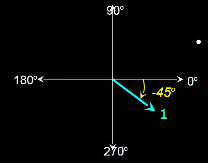
Example of Phasor Representation
Visualize with angles:
Magnitude and phase angles illustrated.
Example phasors:
Phasor with magnitude = 2, phase angle = 45°.
Phasor with magnitude = 3, phase angle = 180°.
Phasor with magnitude = 1, phase angle = -45°.
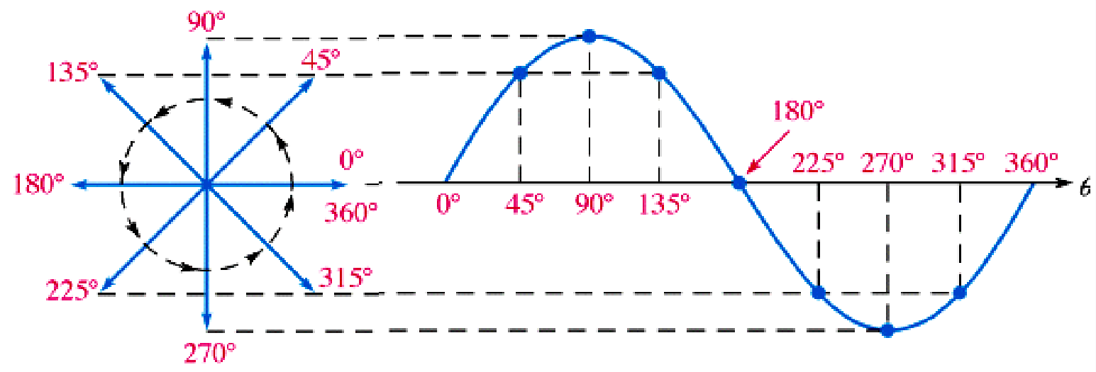
Sine Wave Representation with Phasors
Full cycle of sine wave: Represented by a phasor rotating 360°.
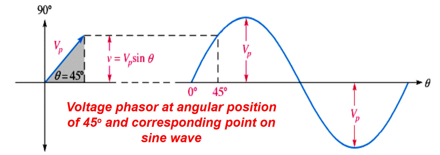
Instantaneous Value: Given by the vertical distance from the phasor tip to the horizontal axis.
Phasor Position and Instantaneous Value Relationship:
Vertical distance indicates the sine wave’s instantaneous value at any point.
Positive and Negative Angles
Phasor angles can be expressed:
Positive angles: Counter-clockwise from 0°
Negative angles: Clockwise from 0°
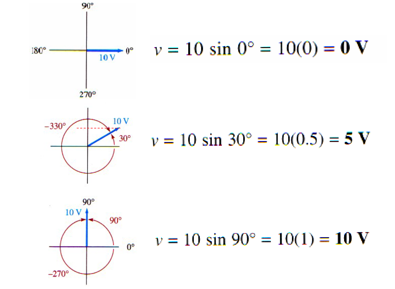
Examples of Phasor Analysis
Example calculation of instantaneous value for different phase angles.
Formula used: Instantaneous value = VP * sin(θ).
Phasors for Multiple Sine Waves (can be more than 2)
Phasor diagrams can illustrate the relationships between multiple sine waves of the same frequency:
A fixed position phasor represents a complete sine wave.
Constant phase angle between sine waves throughout cycles.
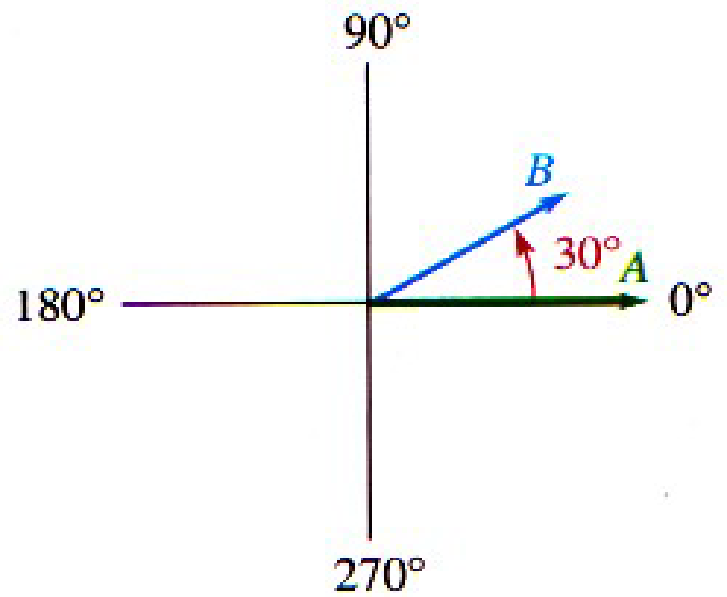
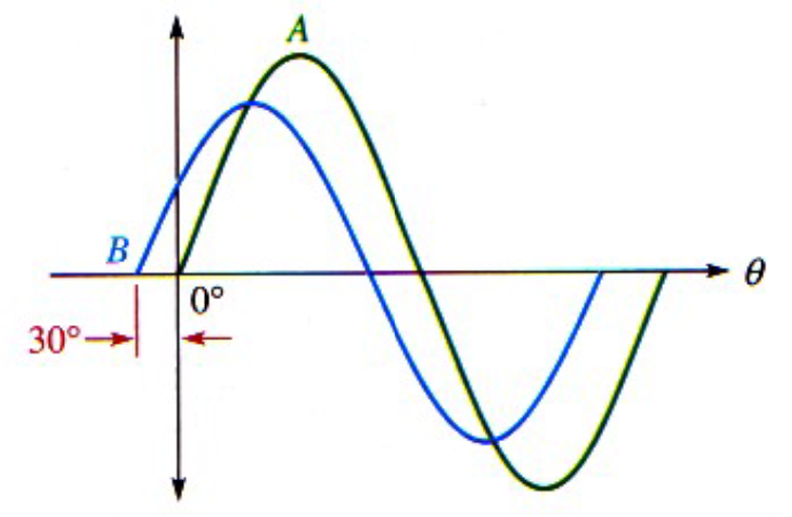
Understanding Phase Relationships
Example: Wave B leads Wave A by 30° with a smaller amplitude indicated by the phasor lengths.
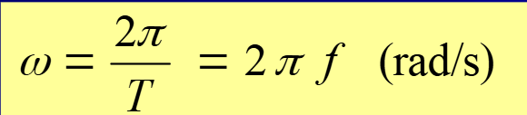
Angular Velocity of Phasors
Cycle Representation: One cycle represented by rotation through 2π radians (360°).
Time Relationship: Time to complete one cycle is the period (T) of the sine wave.
Angular Velocity (ω): Related to the frequency of the phasor.
Formula:
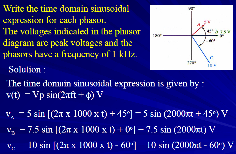
General Expressions for Sine Waves
Instantaneous Voltage: (
Formula:
v(θ) = Vp sin(θ) — angular domain expression
v(t) = Vp sin(2πft) — time domain expression
Examples of Time Domain Expressions:
Specific values calculated from phasor diagrams and frequencies given.
RMS vs Peak Values
Phasors often represented in RMS values for AC voltage or current in circuit analysis.
Notation to clarify that RMS values are used unless specified otherwise.
Summary of Phasors
Phasor diagrams effectively represent sine waves:
Angular position indicates the sine wave angle relative to a reference;
Length of phasor indicates amplitude.
Demonstrates phase relationships across multiple sinusoidal quantities.
Time domain expression: v(t) = Vp sin(2πft + Φ).