Quiz 3 POWPLANT - Reviewer
PPT 7: ACCESSORY SECTION & PROPELLER REDUCTION GEARS
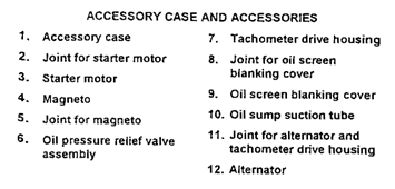
Accessory Section
Material: Cast construction, usually aluminum alloy or magnesium.
Construction: Often cast in one piece with mounting provisions for accessories like magnetos, carburetors, fuel and oil pumps, vacuum pumps, starter, generator, tachometer drive, etc.
Drive Shafts: Mounted in suitable drive arrangements that are carried out to the accessory mounting pads. Arranged to give proper drive speed to magnetos, pumps, and other accessories.
Carburetor
Function: Device that mixes air and fuel to achieve the proper fuel-air ratio for combustion engines.
Types:
Float-type: Fuel delivery based on float mechanism.
Pressure-type: Fuel delivery under pressure via a fuel pump.
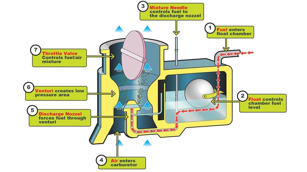
Float-Type Carburetor
Airflow: Air flows through a filter, passes through a venturi creating low pressure, forcing fuel through the main jet, and mixes with the airstream.
Float Mechanism: Controls the fuel level in the float chamber, regulating fuel entering the carburetor based on float position.
Float Chamber: Contains fuel, and a needle attached to the float controls fuel entry by opening/closing a valve.
Fuel Regulation: As the float rises, the needle valve closes the fuel opening and shuts off the fuel flow to the carburetor. The needle valve opens again when the engine requires additional fuel.
Throttle Valve Function: The pilot controls the throttle, adjusting the flow of the fuel-air mixture into the engine.
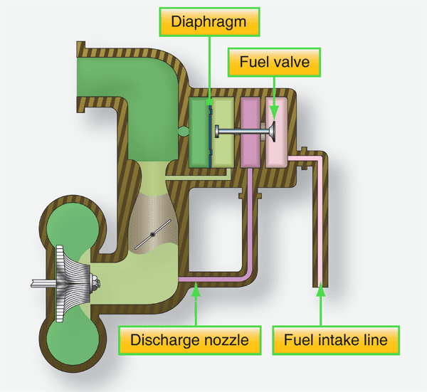
Pressure-Type Carburetor
Fuel Delivery: Discharges fuel into the airstream at a pressure well above atmospheric pressure., improving vaporization and permitting the discharge of fuel.
With the discharge nozzle in this position, fuel vaporization takes place after the air has passed through the throttle valve minimizing temperature drops.
Stability: Performs well even under rapid maneuvers or rough conditions since fuel chambers remain filled under all operating conditions.
Pressure Differential: Air pressure on the right of the diaphragm is lowered because of the drop in pressure at the venturi throat.
As a result, the diaphragm moves to the right, opening the fuel valve, allowing fuel to be sprayed into the airstream.
The distance the fuel valve opens is determined by the difference between the two pressures acting on the diaphragm. This difference is directly proportional to the airflow through the carburetor. Thus, the volume of airflow determines the rate of fuel discharge.
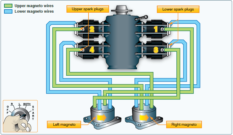
Magnetos
Function: Uses a permanent magnet to generate electricity independent of the aircraft's electrical system.
Voltage: Produces a high voltage to jump a spark at the spark plug gap.
Operation: Begins when the starter engages and continues as long as the crankshaft rotates.
Ignition System: Dual system with two magnetos, separate sets of wires, and spark plugs, each firing one spark plug in every cylinder.
Reliability: Increases reliability; if one magneto or one spark plug fails, the engine continues to run with a slight power reduction.
Combustion: Dual spark plugs improve combustion efficiency and a higher power output.
Starter Motor
Function: Rotates the engine to start it.
Engagement: engages the aircraft flywheel, rotating the engine fast enough for it to start and continue running independently.
Alternator
Function: supply electric current for the aircraft’s electrical system and charges the battery.
Battery: Stores energy for engine starting and as a backup power source if the alternator fails.
Accessory Gear Trains
Gear Types: Spur-type and bevel-type gears are used.
Spur Gears: Typically drive heavily loaded accessories, requiring least play in the gear train.
Bevel Gears: Allow angular positioning of short stub shafts to accessory mounting pads.
Engine Use in opposed, reciprocating engines: Simple arrangements are used.
Propeller Reduction Gears
Purpose: Allows the propeller to turn slower than the engine, optimizing efficiency. This allows an engine to turn at a relatively fast speed and a propeller to turn at a more efficient slower speed.
Gear Types: Includes spur gears, planetary gears, or combinations.
Engine Power: Determined by piston pressure and the number of power strokes in a given period
Remember: the faster an engine turns, the more power it produces; however, this same rule does not apply to propellers.
Propeller Speed must be slower than engine speed for efficiency, as high-speed propeller tips lose efficiency as they approach the speed of sound.
Reduction Gear Systems: Allows the engine to operate at high speed while keeping the propeller at a more efficient, lower speed.
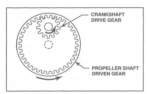
Spur Gears
Tooth Alignment: Teeth cut straight across the circumference, available as external or internal.
Basic Reduction System: Two external-tooth spur gears, one small on the crankshaft, and one large on the propeller shaft.
Amount of Reduction: Determined by the size difference between gears. The larger the gear, the slower the propeller turns. For example, if the drive gear has 25 teeth and the driven gear has 50 teeth, a ratio of 1:2 exists and the propeller turns at one half the crankshaft speed.
Propeller Rotation: Using two external gears causes the propeller to turn in the opposite direction to the crankshaft.
Off-center propeller shafts: act like gyroscopes, placing significant torsional loads on the engine case.
Use of internal-tooth spur gear on the propeller shaft and an external-tooth spur gear on the crankshaft: allows the propeller to turn in the same direction as the engine keeping the propeller shaft more closely aligned with the crankshaft.
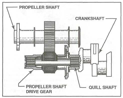
Quill Shaft
Material: Hardened steel, splined on both ends.
Function: Absorbs torsional vibration between two gears or shafts. It minimizes torsional vibration between the propeller shaft and the crankshaft.
Application: Used when the propeller shaft is not perfectly aligned with the crankshaft to reduce vibration.
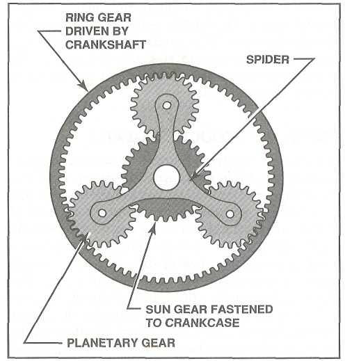
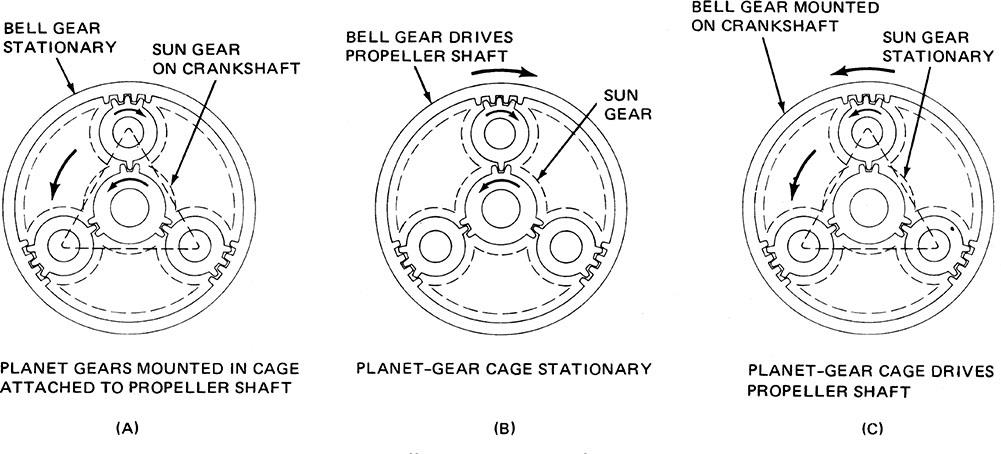
Planetary Gears
Purpose: Keeps the alignment of the propeller and crankshaft to reduce vibration. Transmits power with minimal weight and space while maintaining the propeller's rotation direction.
Components: sun gear, planetary gears, ring/bell gear.
Installation: Crankshaft drives either the sun or ring gear depending on the installation.
Use: Found in horizontally opposed engines, radial engines, and turboprop engines.
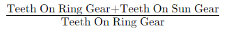
Example: With 72 teeth on the ring gear and 36 teeth on the sun gear, the ratio is 1.5 to 1, traditionally expressed as a 3-to-2 reduction.
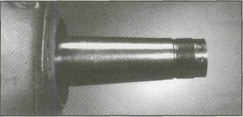
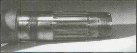
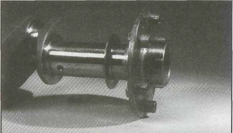
Propeller Shaft
Function: carries a propeller at its end and transmits power from engine to propeller.
Tapered Propeller Shaft: Tapers towards the end of the shaft; used in early low-powered engines.
Splined Propeller Shaft: Has rectangular grooves (splines) with a master spline (twice the size of spline) which minimizes vibration, used in most high-powered radial engines.
Flanged Propeller Shaft: Modern design with a flange forged directly onto the end of crankshaft and a propeller is bolted to the flange, with additional support from a short shaft and studs. Used in most modern horizontally opposed aircraft engines.
PPT 8: CARNOT CYCLE AND OTTO CYCLE
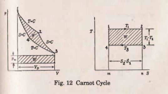
Carnot Cycle
Carnot Cycle: A powerful and efficient heat cycle.
Processes: Consists of two isothermal and two adiabatic processes.
Considered as an Ideal Cycle: No wasteful processes like friction, no heat conduction, and reversible processes. It involves no change in entropy.
Theoretical Thermodynamic Cycle
Inventor: Nicolas Léonard Sadi Carnot (French Engineer).
Year: 1824.
Contribution: Founder of thermodynamics, first recognized the work-heat relationship.
Common Assumptions of Carnot Cycle
Quasi-Equilibrium: Isothermal expansions and compressions.
No Heat Losses in pipes and components.
No Friction thus no pressure drops, and has negligible kinetic and potential energy changes.
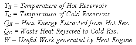
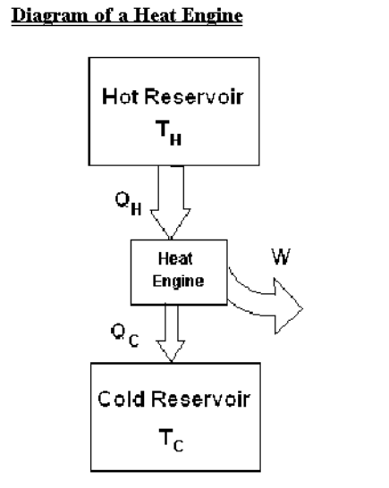
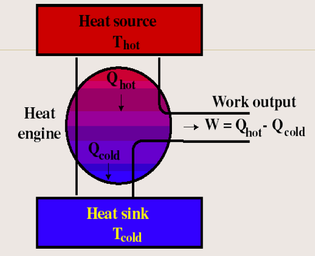
Parts of a Heat Engine
Source (Hot Reservoir): High temperature material with infinite thermal capacity. Provides heat without changing its temperature.
Sink (Cold Reservoir): Low temperature material with infinite thermal capacity. Absorbs heat without changing its temperature.
Working Substance (Ideal gas): Converts heat energy into work, typically an ideal gas in a cylinder with a frictionless piston. The lower side of the cylinder will be thermally conducting.
Insulating Stand: insulates the working substance from thermal contact with the surroundings during adiabatic processes.
Carnot Cycle
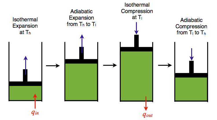
Carnot Cycle: devised an ideal cycle with four thermodynamic processes.
Thermodynamic Process
Isothermal Expansion
Adiabatic Expansion
Isothermal Compression
Adiabatic Compression
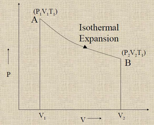
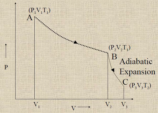
Isothermal Expansion
Process:
The working substance is kept in contact with the source.
The piston of the cylinder is moved outwards.
The gas expands at constant temperature.
The amount of heat(Q1) is absorbed from the source to make the temperature constant.
The volume increases and pressure decreases.
Result: Volume increases, pressure decreases.
Represented by curve AB in the p-V diagram.
Adiabatic Expansion
Process:
The lower conducting side of the cylinder is kept in contact with the insulating stand.
The piston of the cylinder is moved outwards.
The gas expands such that no heat enters the system or leaves from it.
The volume increases and pressure decreases.
The temperature is decreased from T1 to T2.
Result: Volume increases, pressure decreases. Temperature decreases from T1 to T2.
Represented by curve BC in the p-V diagram.
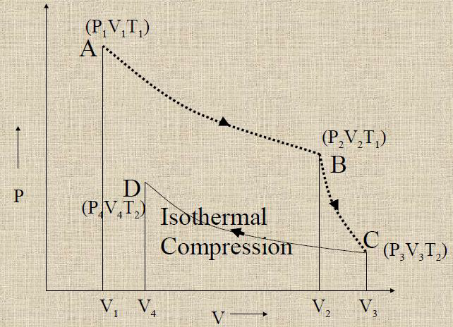
Isothermal Compression
Process:
The cylinder is kept in contact with the sink.
The piston of the cylinder is moved inwards.
The gas is compressed at constant temperature.
The excess heat produced(Q2) will flow to the sink to make the temperature constant.
Result: Volume decreases, pressure increases.
Represented by curve CD in the p-V diagram.
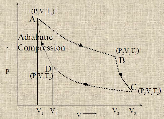
Adiabatic Compression
Process:
The cylinder is kept in contact with the insulating stand.
The piston of the cylinder is moved inwards.
The gas is compressed such that no heat enters the system or leaves from it.
Result: Volume decreases, pressure increases. Temperature Increases from T2 to T1.
Represented by curve DA in the p-V diagram.
Carnot Cycle P-V Diagram
Phases:
1-2. Isothermal Expansion
2-3. Isentropic Expansion
3-4. Isothermal Compression
4-1. Isentropic Compression
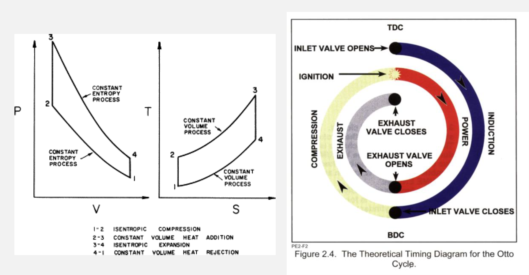
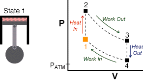
Otto Cycle
Otto Cycle: Used by spark ignition internal combustion engines (2-stroke or 4-stroke cycles).
Process:
Ingest fuel-air mixture
Compress it
cause it to react, thus effectively adding heat through converting chemical energy into thermal energy
Expand
Eject combustion products
History
Inventor: Nikolaus August Otto (German Engineer).
Year: 1876.
First Engine: Four-stroke engine - stationary engine using coal gas-air mixture.
Significance: Common cycle in automobile engines nowadays. It is a typical spark ignition piston engine.
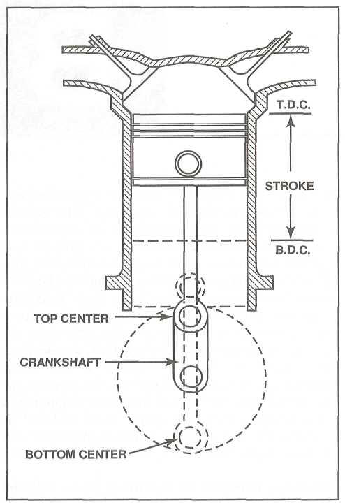
Definition of Terms
Stroke: Distance piston moves in the cylinder.
Top Dead Center (TDC): Piston at top of the stroke.
Bottom Dead Center (BDC): Piston at bottom of the stroke.
Isentropic Compression
Compression Stroke: Gas is compressed adiabatically from phase 2 to phase 3, as the piston moves from bottom dead center to top dead center.
Compression Ratio: Volume ratio (V2/V3).

Isochoric Compression
Ignition Phase: Heat transfer to air while the piston is at rest
at Top Dead Center. (Phase 3 to Phase 4)
Explosion Ratio: Pressure ratio (P4/P3).
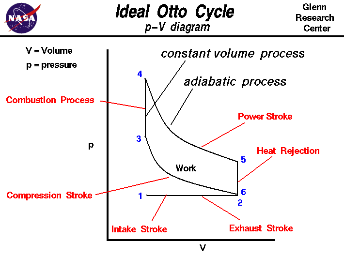
Isentropic Expansion
Power Stroke: Gas expands adiabatically. (Phase 4 to Phase 5)
Isentropic Expansion Ratio: Volume ratio (V5/V4), equals the compression ratio for Otto cycle.

Slide 33: Isochoric Decompression
Exhaust Stroke: Constant volume process with heat rejection while the piston is at the bottom dead center. (Phase 5 to Phase 6)
The working gas pressures drops instantaneously from phase 5 to phase 6. The exhaust valve opens at phase 5.
Exhaust Valve: Opens at the end of this phase, venting gases to the atmosphere.

Otto Cycle
Work Done: ON gas during isentropic compression (2–3), BY gas during isentropic expansion (4–5).
Net Work: Difference in work on and by which corresponds to the area enclosed by the cycle curve.