AC Analysis BJT and JFET
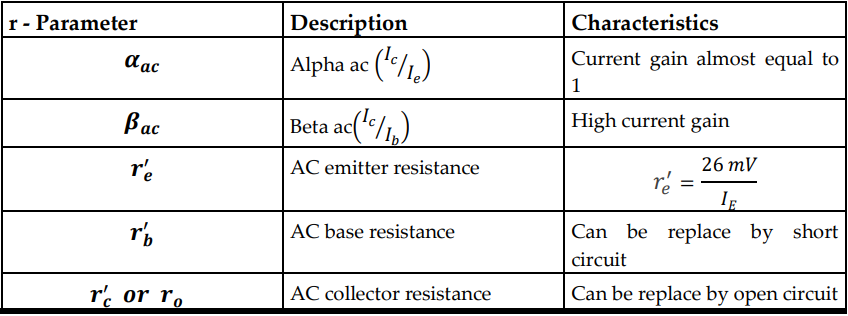
Small Signal Analysis of BJT
An amplifier must be operated at linear region to provide an exact replica of the input signal. This is called Linear Amplifier. One design consideration in small signal analysis is that the transistor must be carefully bias at the center of the AC load line.
1. Common – Emitter
✓ The input is placed at the base and the output is taken at the collector.
✓ Emitter terminal is “common” to the input and output side.
✓ The input a signal is coupled by a capacitor. The output collector terminal has also a capacitor before any load can be connected. The purpose of having a capacitor coupling at the input and output side is to preserve the DC bias operating point.
2. Common – Collector
✓ Also known as “Emitter Follower Circuit”
✓ Input signal is connected at the base and output is taken at the emitter.
✓ Collector is common at the input and output side of the circuit.
✓ There is no phase inversion at the output signal.
✓ High current gain but low voltage gain (Av is almost equal to 1)
✓ Power gain (Ap) is approximately equal to current gain (Ai)
3. Common – Base
✓ Input signal is connected at the emitter and output is taken at the collector.
✓ Base is common at the input and output side of the circuit.
✓ There is no phase inversion at the output signal.
✓ High voltage gain but low current gain (Ai is almost equal to 1)
Multi – Stage Amplifier
The multi – stage amplifier or can be also called “cascaded amplifier”. This type of configuration is used to further increase the gain of the input signal.
Power Amplifiers
Power amplifiers are called large signal amplifiers because it requires large amount of power compare to a small signal amplifier. The power amplifier has a different design consideration to that of the small signal amplifier. In small signal amplifier, the replication of the input signal is very important. However, in large signal amplifier, the main concern is the amount of power and efficiency of the amplifier circuit.
Classes of Amplifier
1. Class A
✓ Q – point is biased at the center of the load line.
✓ The transistor is on during the full input cycle.
✓ Efficiency is up to 25%.
2. Class B
✓ Q – point is biased at the cut – off.
✓ It is uses as push – pull amplifier where two class B transistors are used.
✓ The output of the two transistor is combined at the load.
✓ The transistor is on during only half of the input cycle and turns off at the next half.
✓ It experiences cross over distortion.
✓ Efficiency is up to 50%.
3. Class AB Push – Pull Amplifier
✓ Q – point is biased just above the cut – off.
✓ Two diodes D1 and D2 are used to bias the base – emitter junctions of the
transistor Q1 and Q2. This keep the two transistors slightly on even there are
no input signal.
✓ Efficiency is maximum at 78%.
4. Class C
✓ It is biased below the cut – off.
✓ The transistor only conducts less than 1800 of the input signal as show in
figure 4.8e.
✓ Efficiency is up to 99.99%
✓ Power dissipation and efficiency:
FET Small Signal Model
The major aspect of the FET small signal analysis is that the drain current is controlled by the amount of voltage at the gate to source.
1. Common – Source
✓ The input is placed at the gate and the output is taken at the drain.
✓ Source terminal is “common” to the input and output side.
✓ Output voltage signal has 1800 phase inversion
✓ Power gain (Ap) is equal to the product of current gain and voltage gain.
2. Common – Drain
✓ Also known as “Source Follower Circuit”
✓ Input signal is connected at the gate and output is taken at the source.
✓ Drain is common at the input and output side of the circuit.
✓ There is no phase inversion at the output signal.
✓ High current gain but low voltage gain (Av is almost equal to 1)
✓ Power gain (Ap) is approximately equal to current gain (Ai)
6. Common – Gate
✓ Input signal is connected at the source and output is taken at the drain.
✓ Gate is common at the input and output side of the circuit.
✓ There is no phase inversion at the output signal.
✓ High voltage gain but low current gain (Ai is almost equal to 1)