DC Machines
We don’t normally use DC Machines nowadays
There are two key features of DC machine one is the commutator and the other is the control
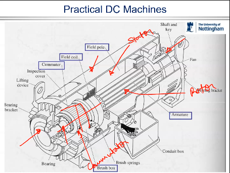
Ideally, a commutator is a big cylinder with strips of
copper.
On it with insulation going in between.
So these strips are electrically isolated from each other.
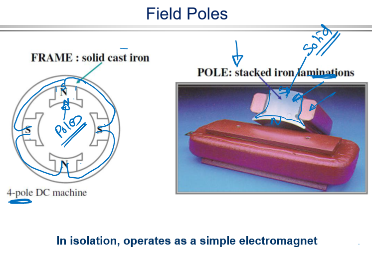
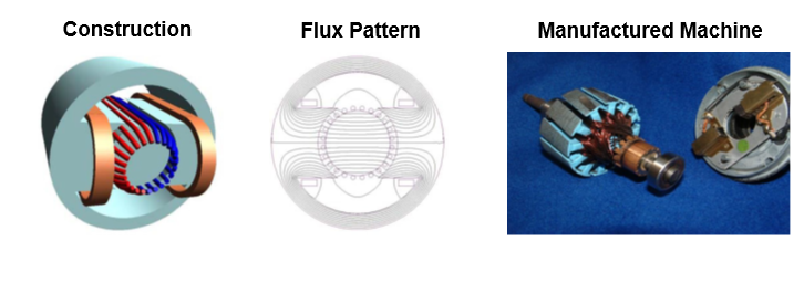
Field Poles
The Rotor in the DC machine is called armature
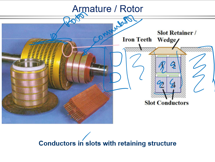
The DC machine in its simplest form has 2 windings
Field Winding - Which is Generally the stator of the machine. This provides the excitation flux, the B in the torque equation. This winding has a low volt-amp product
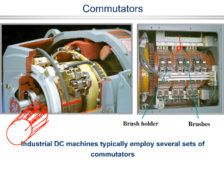
Armature winding - Generally the rotor of the machine , provides the I in the torque equation. The coils of the armature winding are connected to the machines terminal’s via the commutator . Current is transferred via brushes —>You transfer the electricity because the brush is pressing on. The brushes are generally made of carbon, which is a good conductor of electricity in that sense. So you will have a carbon brushes. But looking at the system, the first thing comes to my mind is that it's not an ideal system. Why? Because mechanical systems rubbing against each other, there will be wear and tear. There will be lots of issues around it. The Commutator ensures orthogonal field and torque producing current in the armature winding . This winding has a high volt-amp product and is responsible for energy conversion
What is Special about DC Machines
DC machines are the simplest form of electrical machine in terms of understanding machine operation and in terms of modelling it mathematically. This helps us to understand the concepts of electrical machine operation and is often used as the basis of AC electrical machines control. –d-q axis vector control - Decoupling
For control purposes, the field current can be maintained constant consequently having a constant field. Torque is then directly proportional to the armature current ia.
In an ideal machine we would want the field and armature current to be independently controlled -the DC machine comes very close to this
Physically it is easy to demonstrate the switching and electronic commutation – The Commutator
Commutation and Commutator
What is commutation?
Switching on and off of the current (or changing direction or current) in the section/winding(armature/within the rotor) of the machine is called commutation
Why do we need commutation?
DC machine commutation aims to keep direction of current and direction of field orthogonal to produce a unidirectional peak torque
How can it be achieved?
By using commutator – video shows the importance of the commutator in achieving
Role of Commutator
The commutator plays a very important role in DC machines as it ensures the correct direction of the current under each pole to have a net positive torque produced
As the rotor with its armature winding rotates, the conductors in the slots move from being under one pole (say a north pole) to the next (which will then be a south) – and thus the sign of B changes!
Consequently the direction of I in the conductors must change so that the direction of force and torque remain the same.
This process of changing current direction is called COMMUTATION
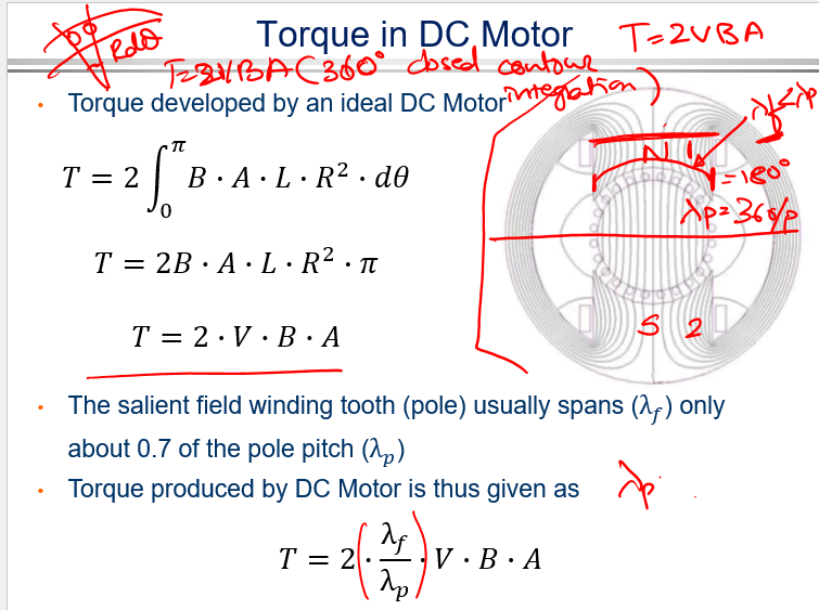
Torque in DC Motor

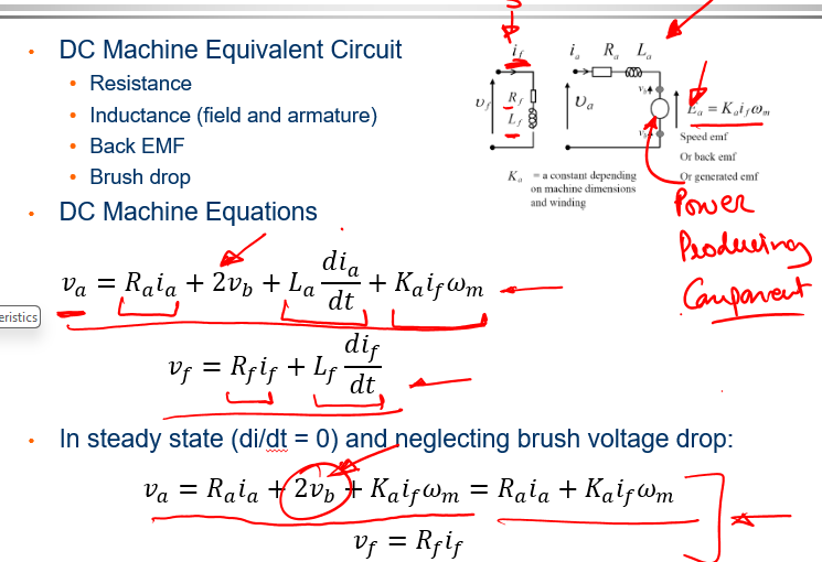
Equivalent Circuit
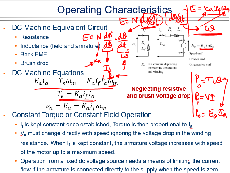
Application Torque Speed Characteristics
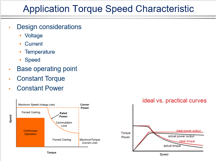
When you have control over voltage, you can manipulate it to create various characteristics in electrical machines. One classic characteristic you might encounter is the torque-speed characteristic of a variable drive system. As you increase the voltage, you must ensure it doesn't exceed the rated value; otherwise, it can lead to short circuits, insulation failure, and severe damage to the machine. Similarly, current should not exceed the rated value, as it can result in excessive losses and potential burnout. In a variable speed system, control typically involves maintaining a constant torque region by adjusting the current while varying the voltage from zero to its maximum value. Once the rated voltage is reached, further adjustments shift to maintaining a constant power region.
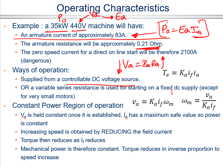
This characteristic, which is often found in variable speed applications, differs from the torque-speed characteristic of a DC machine. The DC machine characteristic, which involves plotting torque versus speed and current versus speed, is derived from specific equations: \(V_A = I_A R_A + E\), \(P_f = I_f R_f\), \(E_A = k_A I_f \omega_m\), and \(k_T = k_A I_A I_f\). To understand these characteristics simply, consider two key points: at the starting point, with zero speed, both current and torque are extremely high because torque is proportional to \(I_A\). As the machine begins to rotate, back EMF builds up, reducing the current until it reaches a rated speed where the current stabilizes and the torque either remains constant, intersects, or levels off. This general behavior outlines the torque-speed characteristic of a dedicated DC machine, and it stems from the aforementioned equations, so encountering such a characteristic should not be surprising.