Waves
Equations
v = λf
Frequency in hertz (Hz)
f = 1 / t
wave speed = wave length * frequency
n = sin( i ) / sin( r )
sin( c ) = 1 / n
Transverse / Longitudinal Waves
Waves can exist as one of two types:
Transverse
Longitudinal
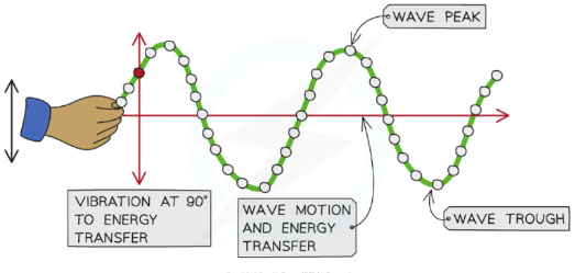
Transverse Waves
Transverse waves are defined as:
Waves that vibrate or oscillate perpendicular to the direction of energy transfer
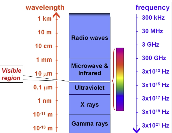
The electromagnetic spectrum is composed of transverse waves
Transverse waves do not need a medium to travel
Longitudinal Waves
Longitudinal waves are defined as:
Waves where the points along its length vibrate parallel to the direction of energy transfer
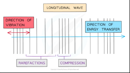 Longitudinal Waves need a medium to travel through
Properties of both wave types
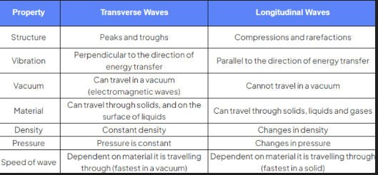 Describing Wave Motion
Amplitude
Amplitude is defined as:
The distance from the undisturbed position to the peak or trough of a wave
It is given the symbol A and is measured in metres (m)
Amplitude is the maximum or minimum displacement from the undisturbed position
Wavelength
Wavelength is defined as
The distance from one point on the wave to the same point on the next wave.
In a transverse wave:
The wavelength can be measured from one peak to the next peak
In a longitudinal wave
The wavelength can be measured from the centre of one compression to the centre of the next
The wavelength is given the symbol λ (lambda) and is measured in metres (m)
The distance along a wave is typically put on the x-axis of a wave diagram
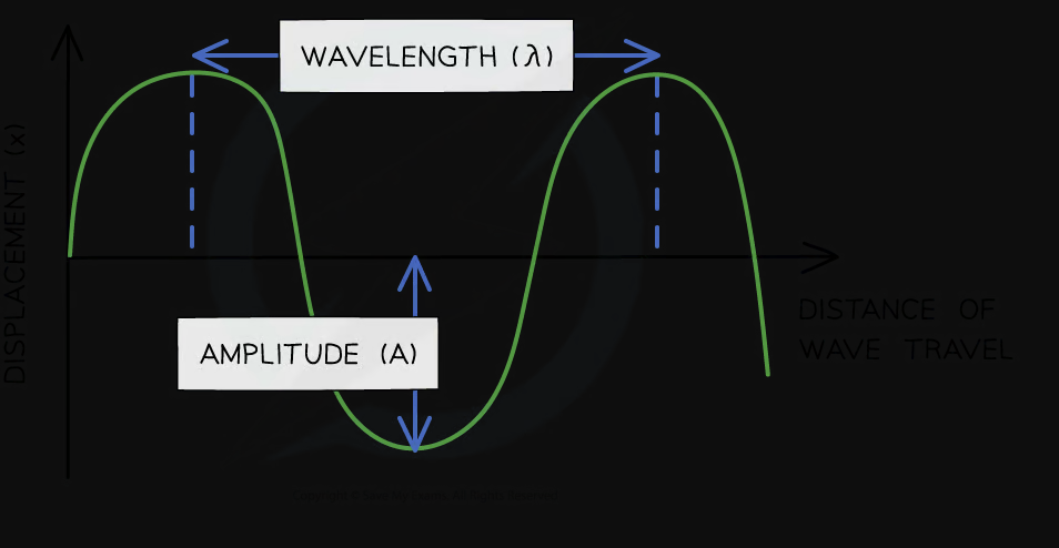
Diagram showing the amplitude and wavelength of a wave
Frequency
Frequency is defined as:
The number of waves passing a point in a second
Frequency is given the symbol f and is measured in Hertz (Hz)
Time Period
The time period (or sometimes just 'period') of a wave is defined as:
The time taken for a single wave to pass a point
The time period is given the symbol T and is measured in seconds (s)
Wavefront
Wavefronts are a useful way of picturing waves from above: each wavefront is used to represent a single wave
The image below illustrates how wavefronts are visualised:
The arrow shows the direction the wave is moving and is sometimes called a ray
The space between each wavefront represents the wavelength
When the wavefronts are close together, this represents a wave with a short wavelength
When the wavefronts are far apart, this represents a wave with a long wavelength
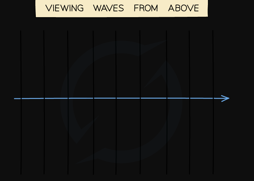
Diagram showing a wave moving to the right, drawn as a series of wavefronts\
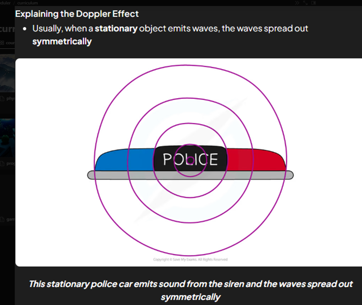
The Doppler Effect
The Doppler Effect is defined as:
The apparent change in wavelength and frequency of a wave emitted by a moving source
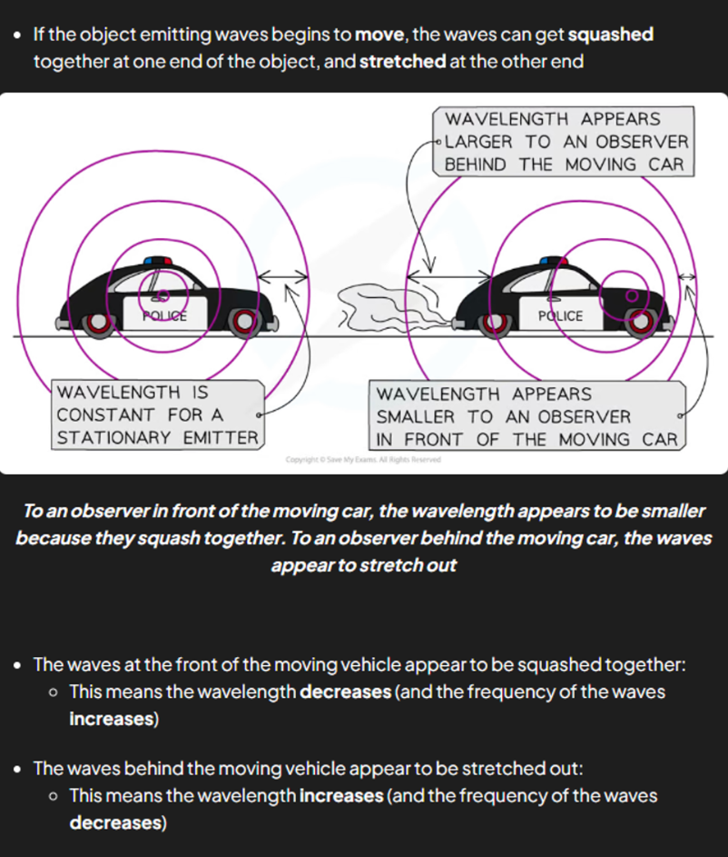
The wavefronts are closer together
The wavelength is shorter, therefore the frequency is higher ( they are inversely proportional)
Wave speed is the same
This is the doppler effect
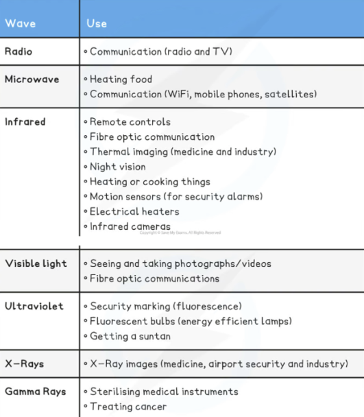
Applications of EM Waves
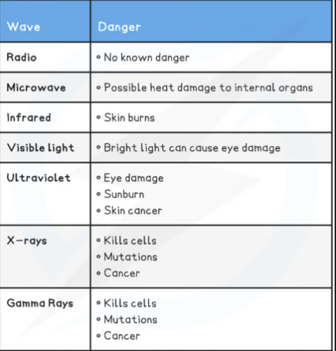
Dangers of EM Waves
All waves, whether transverse or longitudinal, can be reflected and refracted
Reflection occurs when:
Reflection and Refraction
F aster
A way
S lower
T owards
Reflection occurs when
A wave hits a boundary between two media and does not pass through, but instead stays in the original medium

An identical image of the tree is seen in the water due to reflection
Refraction occurs when:
A wave passes a boundary between two different transparent media and undergoes a change in direction

Waves can change direction when moving between materials with different densities
The Law of Reflection
Angles are measured between the wave direction (ray) and a line at 90 degrees to the boundary
The angle of the wave approaching the boundary is called the angle of incidence (i)
The angle of the wave leaving the boundary is called the angle of reflection (r)
The angles are the same, so the law of reflection can be written:
Angle of incidence (i) = Angle of reflection (r)

Angle of incidence and angle of reflection
Ray Diagrams
Reflection Ray Diagrams
Angles are measured between the wave direction (ray) and a line at 90 degrees to the boundary
The angle of the wave approaching the boundary is called the angle of incidence (i)
The angle of the wave leaving the boundary is called the angle of reflection (r)
The law of reflection states that these angles are the same

Ray diagram of reflection of a wave at a mirror
When drawing a ray diagram an arrow is used to show the direction the wave is travelling
An incident ray has an arrow pointing towards the boundary
A reflected ray has an arrow pointing away from the boundary
The angles of incidence and reflection are usually labelled i and r respectively and measured from the normal
Total Internal Reflection
Sometimes, when light is moving from a denser medium towards a less dense one, instead of being refracted, all of the light is reflected
This phenomenon is called total internal reflection
Total internal reflection (TIR) occurs when:
The angle of incidence is greater than the critical angle and the incident material is denser than the second material
Therefore, the two conditions for total internal reflection are:
The angle of incidence > the critical angle
The incident material is denser than the second material

Critical angle and total internal reflection
Total internal reflection is utilised in:
Optical fibres eg. endoscopes
Prisms eg. periscopes
Oscilloscopes
An oscilloscope is a device that can be used to study a rapidly changing signal, such as:
A sound wave
An alternating current

Oscilloscopes have lots of dials and buttons, but their main purpose is to display and measure changing signals like sound waves and alternating current
When a microphone is connected to an oscilloscope, the (longitudinal) sound wave is displayed as though it were a transverse wave on the screen
The time base (like the 'x-axis') is used to measure the time period of the wave

A sound wave is displayed as though it were a transverse wave on the screen of the oscilloscope. The time base can be used to measure a full time period of the wave cycle
The height of the wave (measured from the centre of the screen) is related to the amplitude of the sound
The number of entire waves that appear on the screen is related to the frequency of the wave
If the frequency of the sound wave increases, more waves are displayed on screen
Measure the speed of sound
Use a signal generator with a loudspeaker to produce a sound with a constant frequency
Attach two microphones to a dual channel oscilloscope
Start with the microphones together and move them until the waves are lined up on the screen.
Distance between the microphones is the wavelength
Use f = 1 / t and the oscilloscope to find the frequency
Use v = wl * f to find the speed of sound