Lateral Cephalometrics in Orthodontics
Orthodontic Radiographs
Radiographic Assessment
Radiographs – if appropriate must be justified
For the teeth, bone levels and skeletal pattern
Cephalometric
First: Class II
Second: Class III
Images assess the skeletal pattern and the underlying dentition
Lateral Cephalogram
Used in diagnosis and treatment planning
Allows assessment of AP and vertical skeletal pattern
Incisor positions and angulation
Monitor the progress of treatment
Antero-posterior
Movement of the incisors
Growth modification
Superimpositions
Used in Diagnosis and Treatment Planning
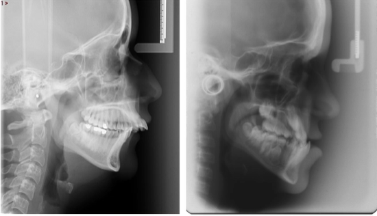
Profile image
Lateral cephalogram
Cephalometrics
Cephalometric landmarks/points are located
Cephalometric planes and relationships are then established using the cephalometric points
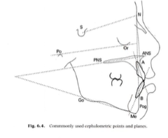
Cephalometric Points
Sella (S) – midpoint of sella turcica (pituitary fossa)
Nasion (N) – most anterior point on frontonasal suture
A point (A) – point of deepest concavity anteriorly on the maxillary alveolus
B point (B) - point of deepest concavity anteriorly of the mandibular symphysis
Orbitale (O) – most inferior, anterior point of the infraorbital rim
Porion (Po) – uppermost outermost point on the bony external auditory meatus
Anterior nasal spine (ANS) – the tip of the anterior nasal spine
Posterior nasal spine (PNS) – the tip of the posterior nasal spine
Gonion (Go) – most posterior, inferior point on the angle of the symphysis
Menton (Me) – most inferior point on the mandibular symphysis
Cephalometric Planes and Relationships
SN line – line connecting the midpoint of sella turcica with nasion, is taken to resemble the cranial base
Frankfort Plane – the line joining porion and orbitale
Mandibular Plane – line joining gonion and menton
Maxillary Plane – the line joining the anterior nasal spine with the posterior nasal spine
Functional Occlusal Plane – the line drawn between cusp tips of permanent molars and premolars (or deciduous molars in mixed dentition)
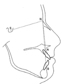
Anteroposterior relationship
SNA – this angle represents the relative A-P position of the maxilla to the cranial base
SNB – this angle represents the relative A-P position of the mandible to the cranial base
Cephalometric
Subtract SNA and SNB to get the ANB angle
ANB – this angle represents the relative A-P position of the maxilla to the mandible and can be used to determine the skeletal class
ANB 2-40 Class I
ANB >40 Class II
ANB <20 Class III
Eastman Correction
Eastman Analysis assumes cranial base (SN) is a reliable basis for comparison
Variation in position N can affect SNA and SNB
Correction made due to varying positions of nasion
Provided SN-MP angle b/n5-110
SNA inc, for every 0 SNA >81, subtract 0.50 from ANB
SNA dec, for every 0 SNA <81, add 0.50 to ANB
Alternative avoid cranial base, or in conjunction with use wits analysis and ballards conversion
Cephalometrics
Upper incisor to maxillary plane angle (UI/Max) – the angle between the maxillary plane and the axis of maxillary incisors
Average 1090 +/- 6
Lower incisor to mandibular plane angle (LI/Mand) – the angle between mandibular plane and mandibular incisors
Average 930 +/- 6
UI/Max and LI/Mand plane angles are used to determine incisal position and if incisors are average inclination, proclined and retroclined
Vertical skeletal relationship
Maxillary – mandibular plane angle (MMPA) angle formed between maxillary plane and mandibular plane
Average MMPA 270 +/4
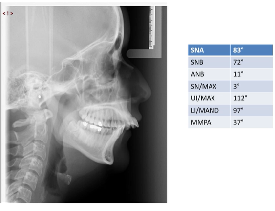
Therefore this patient has:
A skeletal II pattern.
Eastman correction cannot be done.
Upper incisors are within normal limits
Lower incisors are proclaimed
Average LI/MAND is 93o and MMPA of 27o = 1200 total
>120o = proclaimed
<120o = retroclined
Wits Analysis
Compares maxilla and mandible with Functional occlusal plane
FOP – Line drawn b/n cusp tips of the molars and premolars
Wits appraisal and application – Jacobson 1975
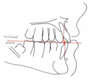
To this function, a perpendicular line is drawn from A point to B point.
The difference then when we extract Ao – Bo gives a value for the Wits analysis