Final Review
Chapter 3 Slides 53-85
Overview of TCP
Point-to-point
One sender, one receiver
Reliable, in order byte stream
Pipelined
Dynamic window size
Full duplex data
bi-directional data flow in same connection
MSS: maximum segment size
Connection oriented
Handshaking before data exchange
TCP Segment Structure
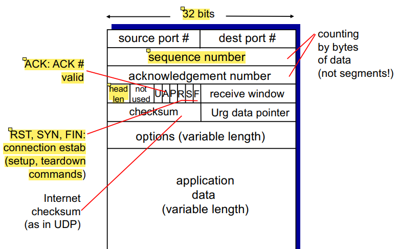
variable length header, so we must specify its length in head len
much more overhead than UDP
A = ACK valid. Checks validity of ACK number, used for piggybacking
Because bi-directional data flow (data can flow both ways), allows the piggybacking of ackowledgements
If client sends something
If server has data to send, it’ll also sent it with the ACK to combine them, rather than separating them
RST,SYN,FIN, used for connection establishment and management
TCP Sequence Numbers and ACKS
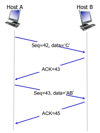
Sequence numbers
Number of first byte in segments data
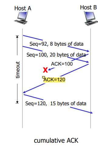
Ackowledgements
Seq # of next expected byte to receive
Cumulative ACKs!
Handling out-of-order segments is up to implementor to decide
TCP Round Trip Time, Timeout
SampleRTT = measured time from segment transmission until ACK receipt, ignores retransmissions
EstimatedRTT = (1 - a) * EstimatedRTT + a * SampleRTTTypical value, a = 0.125
For our timeout interval, we give a safety margin on top of EstimatedRTT just in case! Which depends on the typical derivation between Sample (actual) and Esimated (average)
DevRTT = (1-B) * DevRTT + B * |SampleRTT - EstimatedRTT|Typically, B = 0.25
TimeoutInterval = EstimatedRTT + 4 * DevRTTTCP Sender Events
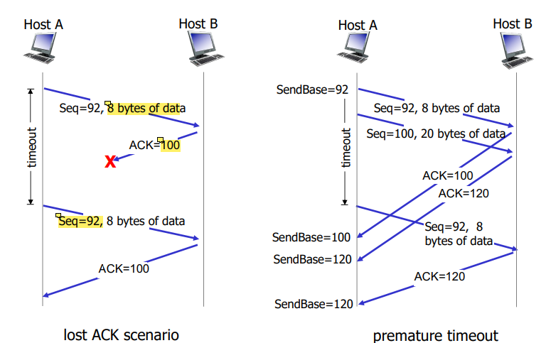
Data received from application:
Create segment with sequence number
Sequence number is byte stream number of first data byte in segment
Start timer if not already running
Time is essentially for oldest unACKed segment
Timeout = TimeOutInterval
Timeout
Retransmit segment that caused timeout
Restart timer
ACK Received
If ACK ackowledges previously unACKed segments
Update what is known to be ACKed
start timer if there are still unACKED segments
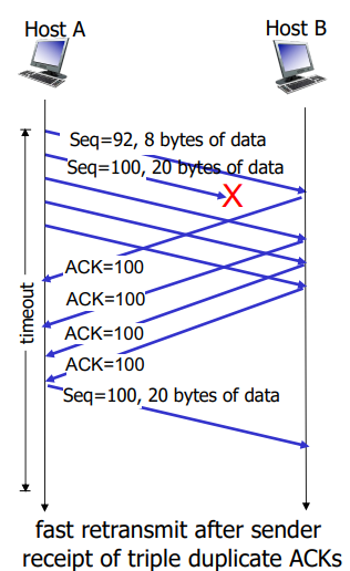
TCP Fast Retransmit
If sender receives 4 ACKs for the same data, resend unACKed segment with the smallest sequence number
Likely that segment was lost, so don’t wait for timeout
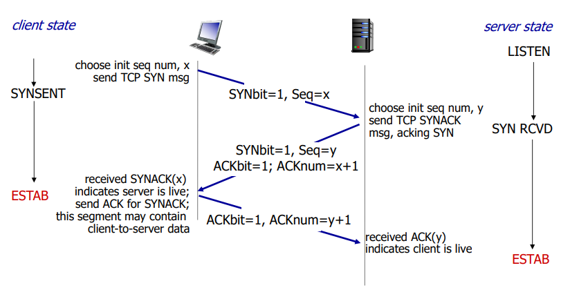
TCP 3 Way Handshake
TCP Closing a Connection
Client and server each close their side of the connection
Send TCP segment with FIN bit = 1
Respond to received FIN with ACK
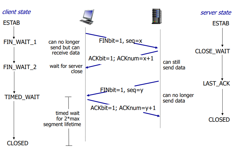
Timed wait is 2 * max segment lifetime!
Once the FIN bit is sent, that side can no longer send data but can receive data
Network Congestion
Too many sources sending too much data too fast for network to ahndle
Manifestations:
Lost packets (buffer overflow at routers)
Long delays (qeueing in router buffers)
Solution:
Ask sources to reduce their sending rate!
TCP Congestion Control: Additive Increase, Multiplicative Decrease
Sender increases transmission rate (window size), proving for usable bandwidth until loss occurs
Additive increase = increase cwnd by 1 MSS every RTT until loss detected
Multiplicative decrease = cut cwnd in half after loss
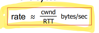
Sent (Not yet ACKed) packets = LastByteSent - LastByteACKedTCP Slow Start
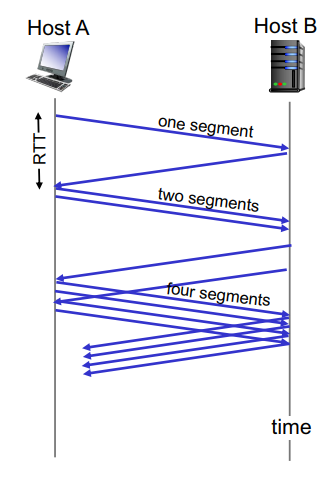
When conneciton begins, increase rate exponentially fast
Initially, cwnd = 1 MSS
Double cwnd every RTT
TCP: Detecting and reacting to loss
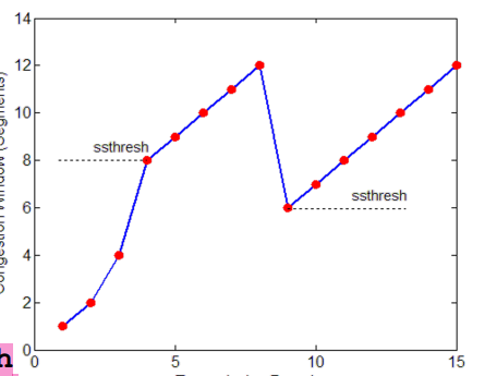
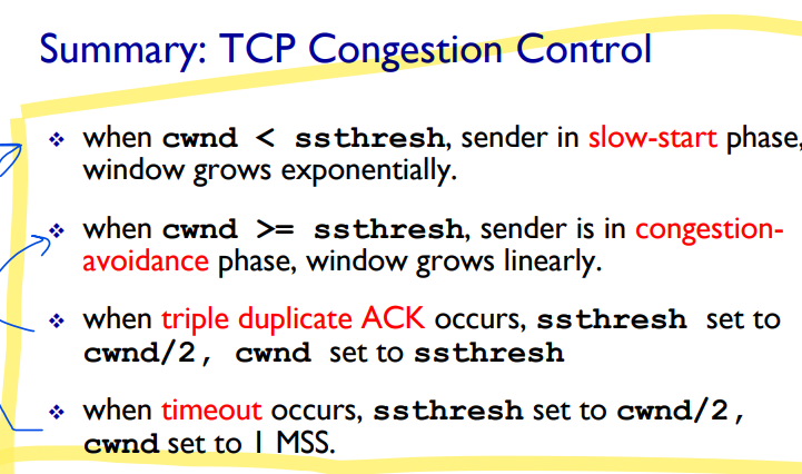
Loss indicated by timeout:
cwnd set to 1 MSS
Window then grows exponentially (as in slow start) to a threshold, then grows linearly
Loss indicated by 3 duplicate ACKs
cwnd is cut in half, then grows linearly
When does exponential increase switch to linear? When CWND reaches ssthresh (slow start thresh)
ssthresh is variable, on loss event, it is set to ½ of cwnd just before the loss event
TCP Throughput
avg TCP throughput = 3/4 (W/RTT) bytes/secTCP Fairness
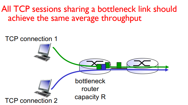
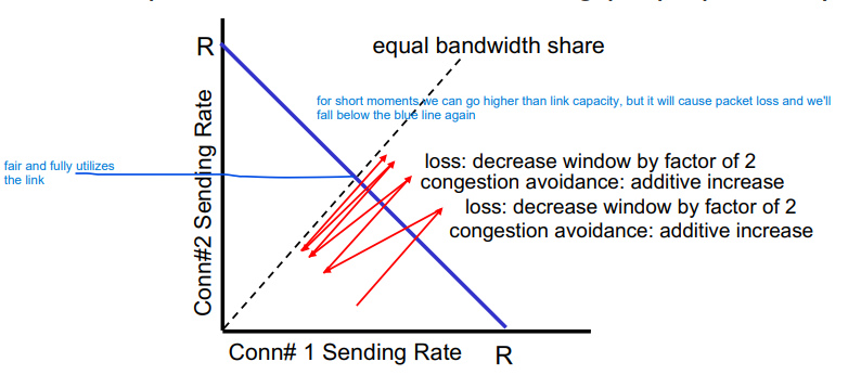
Fairness goal: If K TCP sessions share the same bottleneck link of bandwidth R, each should get 1/K of the link bandwidth
Why is TCP fair?
additive increase gives slope of 1 as throughput increases
multiplicative decrease decreases throughput proportionally
More on Fairness
Multimedia apps often do not use TCP
Don’t want rate throttled by congestion control
Instead use UDP
Send audio/video at constant rate, tolerate packet los
Application can open multiple parallel connections between two hosts
Web browsers do this
e.g Link of rate R with 9 existing connections
new app asks for 1 TCP gets 1/10 of link capacity
new app asks for 11 TCPs gets 11/20 ~ ½ link capacity
Chapter 4
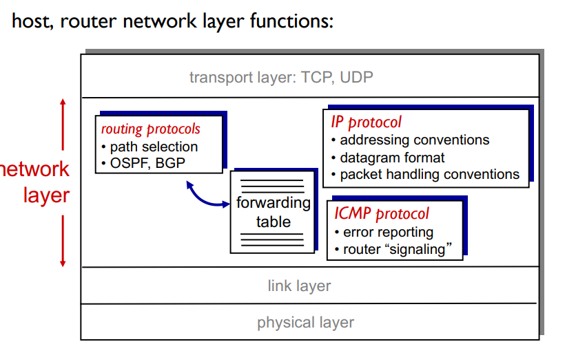
Network Layer
transports segment from sending to receiving host
On sending side encapsulates segments into datagrams
On receiving side, delivers segments to transport layer
Network layer protocols in every host, router
Router examines header fields in all IP datagrams passing through it (let’s it figure out wherre to send it via IP address)
Two key network-layer functions
Forwarding: Move packets from router’s input to appropriate router output
Like the process of getting through a single interchange
Routing: determine route taken by packets from source to des0tination
Process of planning trip from source to destination
Network layer: Data plane and control plane
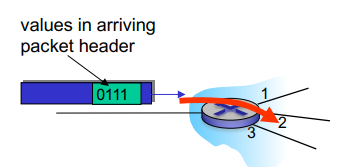
Data Plane:
local, per-router function
determines how datagram arriving on router input port is forwarded to router output port
forwarding functionality!
Control Plane:
Network-wide logic
Determines how datagram is routed among routers along end-end path from source host to destination host
Two control-plane approaches
Traditional routing algorithms = implemented in routers
Software-defined networking = implemented in (remote) servers
Traditional Approach: Per Router Control Plane
Individual routing algorithm components in each and every router interact in the control plane
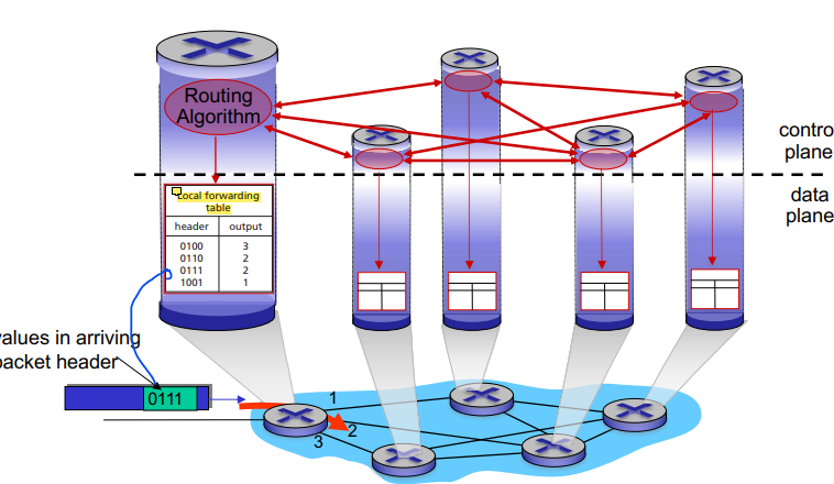
Each row of the local forwarding table has 2 values
For every possible destination - the proper outgoing link of the router
Header = destination, adress, output = proper link
Each router implmeents both the data and control plane within themselves!
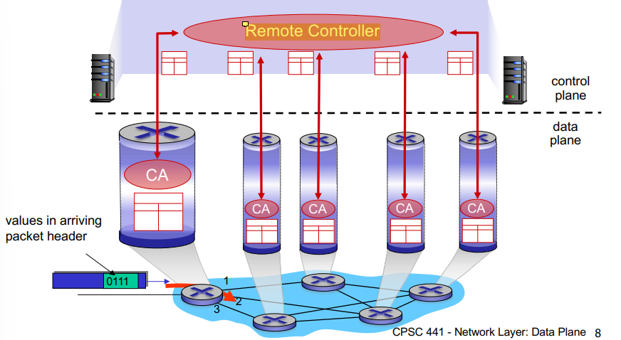
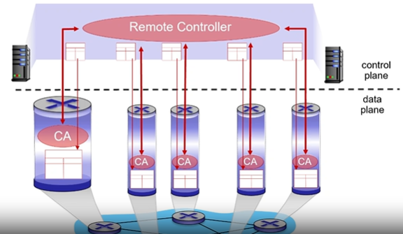
Logically Centralized Control Plane (Non Traditional) (SDN)
A distinct (typically remote) controller interacts with the local control agents (CA’s)
The remote controller talks to each router, computes forwarding tables, and sends the tables to the routers so they can do their local forwarding
Routers not involved in control plane operations
Overview of Router Architecture
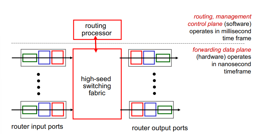
Input Port Functions:
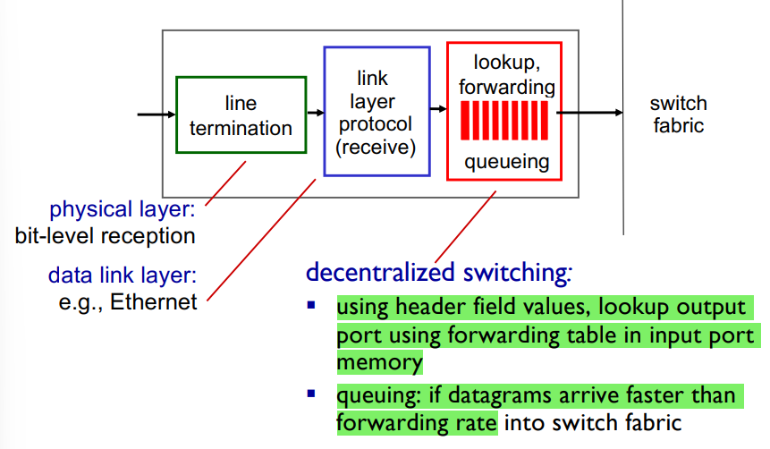
First part implements the physical layer
Bit reception, sends to link layer
Link layer: Receives, then delivers datagrams to third module
Third module = Does table look up
Receives datagrams
Uses their header values to lookup the outgoing port in the forwarding tabke
Then it writes a datagram with the outgoing port
Switching fabric reads this info and sends to the proper port
Approaches to looking up in the forwarding table:
Destination based forwarding = forward based only on destination IP address (traditional)
Generalized forwarding = forward based on any set of header field valyes (SDN)L
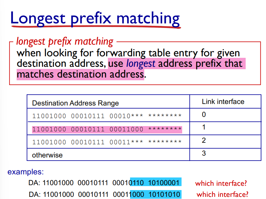
When looking things up in the forwarding table, we use the longest address prefix that matches the destination address
Switching Fabrics
Transfer packet from input buffer to appropriate output buffer
Switching rate = rate at which packets can be transferred from inputs to outputs
Switching Fabric Capacity = # port * capacity of each portThree types of switching fabrics
Memory
Use a computer to emulate router function, reads packets from incoming port, looks up address, sends to outgoing
Not for serious networking
Bus
Only one transfer at a time
Usually in lower capacity switches
One bus connection all input and output ports
Crossbar
Multiple transfers can happen simultaneously
Higher end routers with high capacity
Many buses in parallel (as long as they’re all coming from diff input ports and going to different output ports)

Output Ports
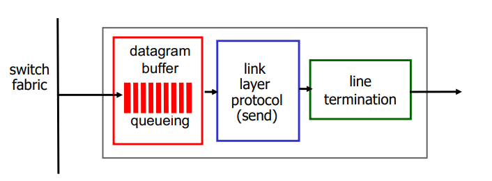
Buffering required when datagrams arrive from fabric faster than the transmission rate
Datagram (packets) can be lost due to congestion, lack of buffers
Scheduling discipline choose among queued datagrams for transmission
Priority scheduling = who gets best performance, network neutrality
By default, it’s FIFO (first in first out)
How much buffering?
RFC 3439 rule of thumb: average buffering equal to a typical RTT times link capacity C
Avg buffer AKA Delay-Bandwidth Product = Max cwnd = C * RTT
avg buffering = typical RTT x link capacityE.g 250 msec RTT, C = 10 Gbps link capacity
Buffer = 0.25 sec * 10 Gbps = 2.5 Gbit buffer!
The Internet Network Layer
IP Datagram Format
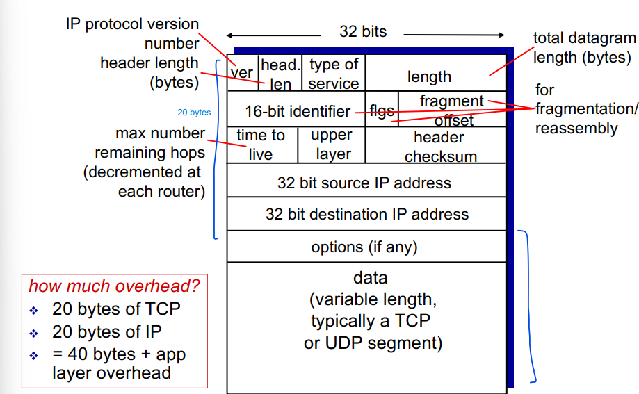
20 byte TCP
20 byte IP
Total overhead = 40 bytes + app layer overhead
Time To Live = Counter that decrements by 1 each time the datagram passes through a router
Upper layer = if its a TCP or UDP segment
The fragmentation stuff is used when one datagram is fragmented into several smaller ones
IP Fragmentation, reassembly
Network links have MTU (max transfer unit) = the largest possible link level frame
Different link types, different MTUs
Large IP datagrams are divided (fragmented) within net
One datagram becomes several datagrams
They are reassembled only at the final destination
IP header bits are used to identify and order related fragments
IP Addressing: Introduction
IP Address = a 32 bit identifier associated with each host or router interface
Interface: A connection between host/router and physical link
Routers typically have multiple interfaces
Host typically has one or two interfaces
IP Addresses associated with each interface
IP Addresses are written in dotted decimal notation:

Subnets:
Device interfaces that can physically reach each other without passing through an intervening router
IP Addresses have structure:
Subnet part = devices in same subnet have common high order bits
Host part = Remaining low order bits
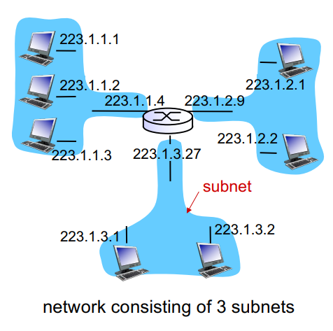
How are interfaces in a subnet connected?
Ethernet switches or wifi base stations
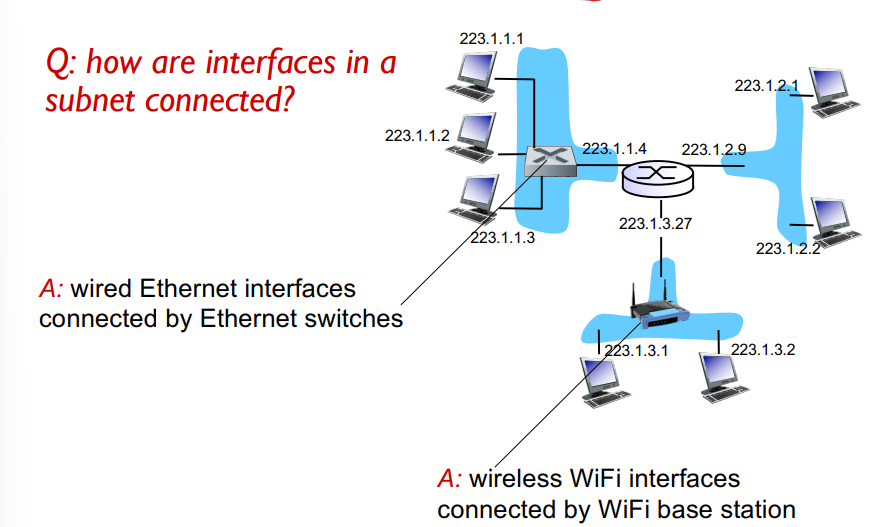
Recipe for Subnets
to determine the subnets, detach each interface from its host or router, creating islands of isolated networks
Each isolated network is called a subnet!

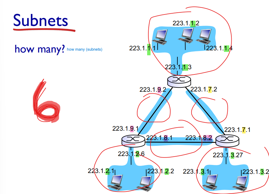
IP Addressing: CIDR
CIDR = Classless InterDomain Routing
Subnet portion of address is arbitrary length
Address format: a.b.c.d/x where x is the # bits in the subnet portion of the address!

How does a host get an IP address?
Hard-coded by sysadmin in config file in the past, but now:
DHCP: Dynamic Host Configuration Protocol: Dynamically get address from a server
DHCP: Dynamic Host Configuration Protocol
Goal = host dynamically obtains IP address from network server when it joins network
Can renew its lease on address in use
Allows reuse of addresses (only hold address while connected/on)
Support for mobile users who join/leave network
Is an application layer portocol
client server architecture
uses UDP for transport
client port = 68, server port = 67
Subnet address specifies a range of addresses we can assign within that subset
192.162.1.0 means we can assign from there to 192.168.1.255
DHCP: What else can it do?
Can return more than just allocated IP address on subnet:
Address of first hop router for client
The gateway router, so we can communicate with hosts outside of the network
name and IP address of DNS server
network mask (indicating network versus host portion of address)
DHCP: Example
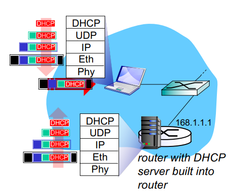
Connecting laptop needs its
IP address
addr of first hop router
address of DNS server,
uses DHCP
DHCP request encapsulated in UDP, encapsulated in IP, encapsulated in Ethernet
Ethernet frame broadcasts on LAN
This means its broadcasted to everyone in the network, including the DHCP server
DHCP receives it, looks at range of IP addresses it has, finds an available one, and returns it
Ethernet de-encapsulated to IP, UDP, and eventually DHCP
DHCP server formulates DHCP ACK containing
Clients IP address
IP address of first hop router for client
Name and IP address of DNS server
Encapsulating of DHCP server, forwarded to client
Client no knows all the info it wanted
IP Addresses: How does the network get the subnet part of IP address?
It gets allocated a portion of its provider ISPs address space

32 bits in an IP address
The ISP block is 20 bits (specified in green)
So ISP has 2^12 IP addresses left (32-20)
We can further divide those 12 into subnets
Each organizations IP addr has 23 bits (specified)
the next 3 bits are for subnets (23-20). So each organization is thus given 2^9 IP addresses
IP Addressing: How does an ISP get block of addresses?
ICANN: Internet Corporation for Assigned Names and Numbers
Allocates addresses
Manages DNS
assigns domain names, resolves disputes
NAT: Network Address Translation
In the local network:
Datagrams with source or destination in this network have 10.0.0.0/24 for source, destination
All datagrams LEAVING the local network have the same single source NAT IP address, 138.76.29.7 in the example below, but different port numbers
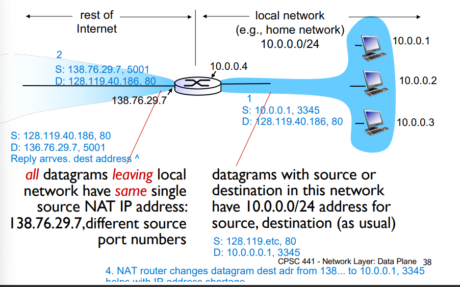
Motivation: local network uses just one IP address as far as the outside world is concerned
Range of addresses not needed from ISP: just one IP address for all devices
Can change addresses of devices in local network without notifying the outside world
can change ISP without changing addresses of devices in local network
devices inside local net not explicitly addressible or visible by outside world (good for security!)
NAT: Network Address Translation
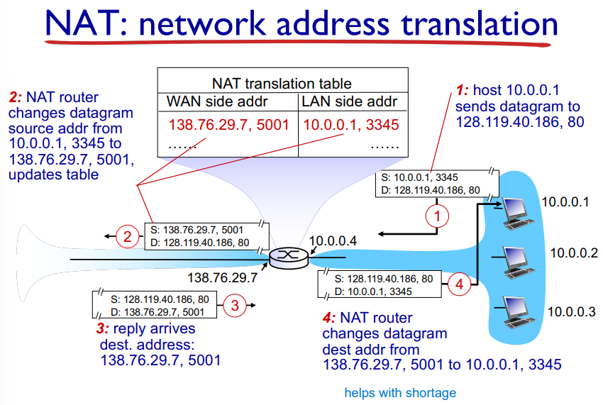
Host A sends datagram to outside destination B
Datagram reaches NAT router, which changes the source address A to A’, and updates this in the NAT table
Reply arrives with destination address A’
The NAT router changes the datagram destination address from A’ to A by using the NAT table!
IPv6 Motivation:
The 32 bit address space of IPv4 is soon to be completely allocated!
128 bit addresses in IPv6
Additional motivation: header format helps speed up processing/forwarding
fixed-length 40 byte header rather than variable length (takes time to check how long a header is) makes routers faster
No fragmentation allowed
Checksum is removed to reduce processing time at each hop (Has to be recalculated with each hop of the datagram since TTL field is updated)
IPv6 Datagram Format
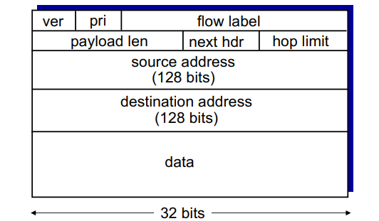
much simpler
version = ver
pri = priority of the datagram
* flow label = sequence of packets can be labeled by the source to be part of the same “flow”
payload length
next header = next header protocol
hop limit = TTL (the number of hops a datagram is allowed to do)
Transition from IPv4 to IPv6
Not all routers can be upgraded simultaneously
How will network operate with mixed IPv4 and IPv6 routers?
Possible solution = tunneling
IPv6 datagram carried as payload in IPv4 datagram among IPv4 routers
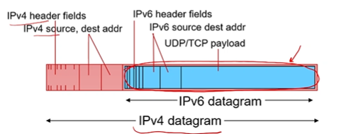
Tunneling: Continued
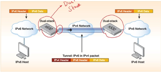
Dual stack routers, as they must understand both IPv4 and IPv6
Create a tunnel over the IPv4 network
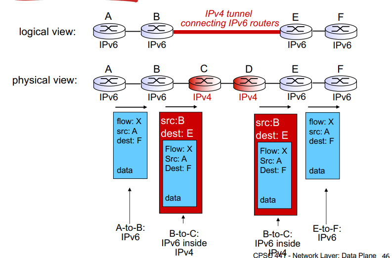
First transfer: src A, destination is final destination
Next router encapsulates this and sets the destination to the next available IPv6 router
Goes through the tunnel
Next IPv6 router opens the datagram to see the IPv6 datagram with destination final destination
Sends to final destination as normal!
Chapter 5
Routing: Determines route taken by packets from source to destination (control plane)
Two approaches to structuring network control plane:
Per router control (traditional)
Logically centralized control (software defined networking)
Per-Router Control Plane
Individual routing algorithm components in each and every router interact with each other in control plane to compute forwarding tables
Distributed implementation of routing algorithms
Logically Centralized Control Plane
A distinct (typically remote) controller interacts with local control agents (CA's) in routers to computer forwarding tables
Routing Protocol
Goal: Determine good paths from sending host to receiving host, through network of routers
Good = least cost, fastest, least congested
Graph Abstractions of Networks
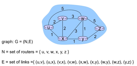
Abstract away subnets, only include their router! (gateway router connects the subnet to the rest of the network)
Every link has an associated cost! E.g from u to w we see it is 5
Cost can come from bandwidth or congestion
Routing Algorithm Classification
Global or decentralized information
Global:
All routers have complete topology, link cost info
“link state” algorithms
Decentralized
Router knows physically connected neighbors, link costs to neighbors
Iterative process of computation, exchange of info with neighbors
“Distance vector” algorithms
Static or dynamic?
Static:
Routes change slowly over time
Dynamic:
Routes change more quickly
Periodic update
In response to link cost changes
Dijkstra’s Algorithm
A link state algorithm (Global), all nodes have the same info
Computes least cost paths from one node to all other nodes, making forwarding tables for that node
Iterative: after k iterations, knows least cost paths to k destinations
Complexity = O(n²) with O(nlogn) possible
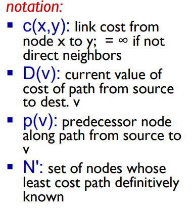
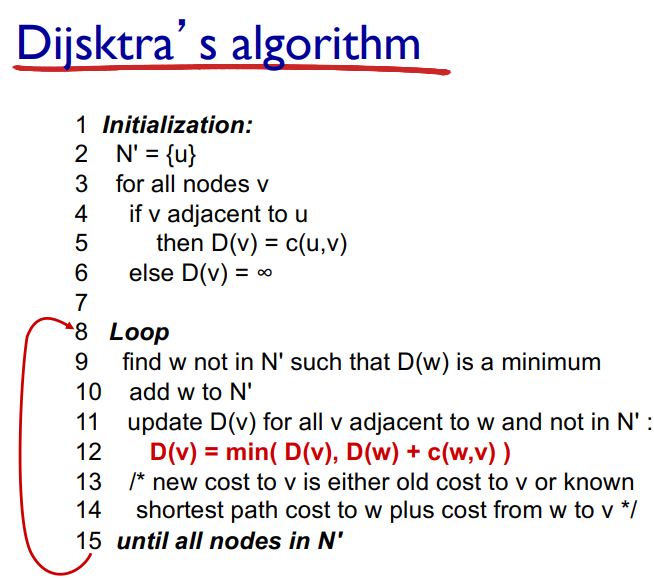
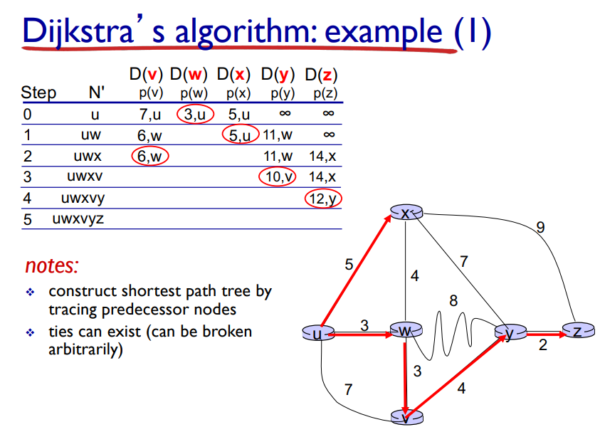
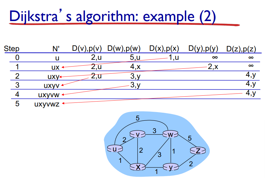
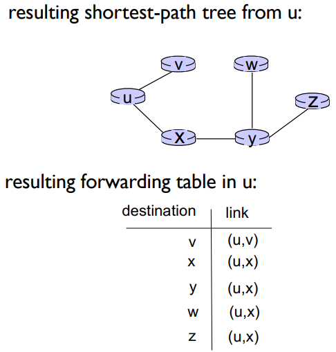
Notation: Link = first “turn” you take from the beginning
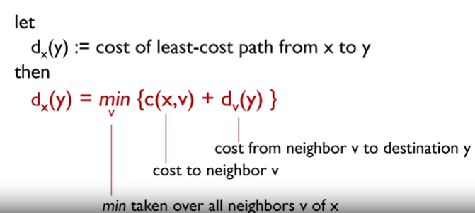
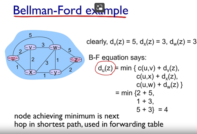
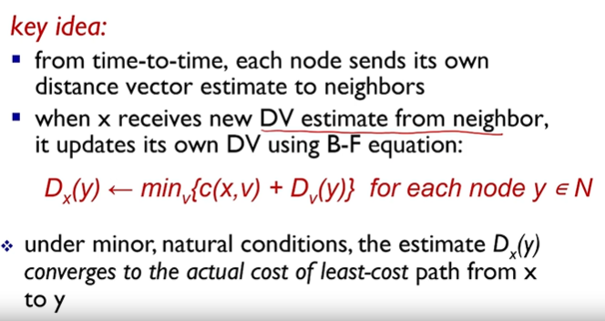
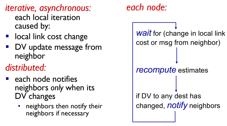
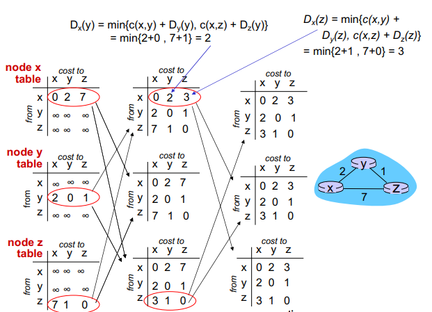
Distance Vector Routing Algorithm - Bellman-Ford equation (dynamic programing)
Finish video and get up to slide 27, brain was not bothered to focus on this one
Comparison of LS and DV algorithms
Message complexity:
LS = each node broadcasts link information to every other node
DV = exchange between neighbors only, but over several rounds
Speed of convergence
LS = very fast (O n log n)
DV = generally slower than LS
Robustness: what happens if router malfunctions
LS
Node can advertise incorrect link cost
Each node computes only its own table
More robust
DV
DV node can advertise incorrect path cost
Each node’s table used by others, so the error propagates
Making Routing Scalable
So far we’ve done idealized routing
All routers identical
Flat network
Scale: with millions of destinations
Routing table exchange would swamp links!
Very long time to compute routes
Administrative autonomy
Internet = network of networks
Each network admin may want to control routing in its own network
Internet Approach to Scalable Routing
Aggregate routers into regions known as “autonomous systems” aka “routing domains”
Instra-AS routing
Routing among hosts, routers, in the same AS “network”
all routers in AS must run the same intra-domain protocol
gateway router at the edge of its own AS has links to other routers in other AS’s
Inter-AS routing
Routing among AS’s
gateways perform inter domain routing, as well as instra domain routing
Gateways must run both instra-domain and inter-domain protocol
Forwarding Tables in Interconnected ASes
The forwarding table uses both inter and instra-AS routing algorithms
If the destination is with the AS, use intra
if the destination is outside of AS, use instra AND inter
Inter-AS Tasks

If a router in AS1 needs to reach another router in AS1 (e.g 1a to 1b):
The AS already has the forwarding table within itselves, and just uses intra-AS routing to get there
If a router in AS1 needs to reach a router outside of AS1:
AS1 must:
learn which destinations are reachable through AS2 and AS3 (since we have two gatway routers from AS1 in this case to these AS’es)
Propogate this reachability info to all the routers in AS1 using inter-AS routing
Intra-AS Routing
Also known as interior gateway protocol (IGP)
Most common intra-AS routing protocols:
RIP = Routing Information Protocol
Distance Vector Routing
IGRP = Interior Gateway Routing Protocol
OSPF = Open Shortest Path First
IS-IS protocol essentially the same as OSPF
Widely used in practice
Link State
OSPF (Open Shortest Path First)
Open = publicly available
Uses Link-State algorithm
all info about link states are broadcasyed!
route computation using Dijkstra’s algorithm
Router floods OSPF link state advertisements to all other routers in entire AS (broadcasting link state info)
Carried in OSPF messages directly over IP (using network layer stuff even though its in the network layer!)
link-state: for each attached link
Internet inter-AS routing: BGP
BGP (Border Gateway Protocol) = the inter-domain routing protocol of the Internet
Like the glue
BGP provides each AS a means to:
eBGP: obtain subnet reachability information from neighboring ASes
runs in external systems
iBGP: propagate reachability information to all AS-internal routers
runs in internal systems
determine “good” routes to other networks based on reachability information and policy
“allows subnet to advertise its existence to the rest of the internet: “I am here
eBGP, iBGP connections
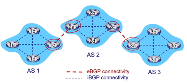
gateway routers run both eBGP and iBGP protocols
internal routers just run iBGP
BGP Basics
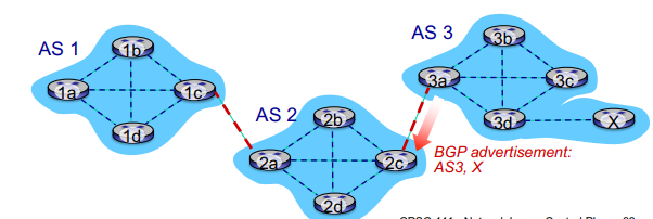
BGP session = two BGP routers exchange BGP messages over TCP connection
advertising paths to different destination network prefixes (BGP is a “path vector” protocol)
Paths are in the format of a list of AS’s that we have to pass through, e.g AS1,AS2,AS3
when AS3 gate router 3a advertises path AS3,X to AS2 gatway router 2c
AS3 promises to AS2 it will forward datagrams towards X
Basically by saying AS3,X AS3 is saying if you give me something, I can get it to X
Path attributes and BGP routes
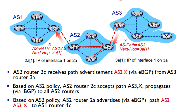
Advertised prefix includes BGP attributes
prefix + attributes = “route”
two important attributes
AS-PATH = list of ASes through which prefix advertisement has passed (the route to get back to AS3 i believe)
NEXT-HOP = gateway router that advertised the route
E.g 3a[1]
Helpful example:
BGP Path Advertisement: Multiple Paths!
A gateway router may learn multiple paths to a destination
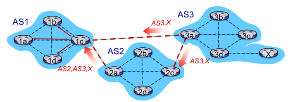
In the example above, AS1 knows AS2,AS3,X is a path AND AS3,X is a path
Based on policy, AS1 gateway router 1c chooses path AS3,X and advertises the path within AS1 via iBGP
BGP, OSPF, forwarding table entries: How does the router set forwarding table entry to distant prefix?
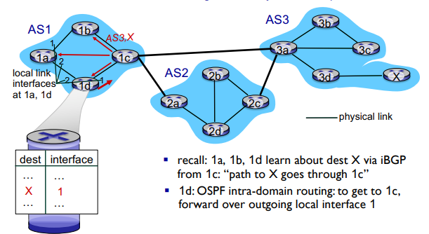
You just put the forwarding that that router would take to get to the gateway router to the AS it needs to go through to get to X
BGP Route Selection
Router may learn about more than one route to destination AS, selects route based on
local policy
shortest AS-PATH
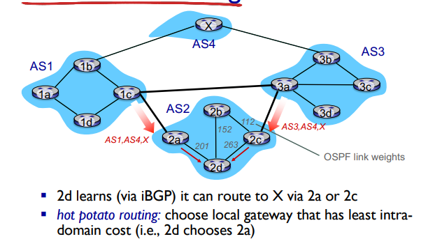
closest NEXT-HOP router: host potato routing
Least intra-domain costs
additional criteria
Hot Potato Routing
ICMP: Internet Control Message Protocol
used by hosts and routers to communicate network level information
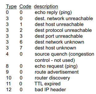
error reporting, unreachable host, network port, protocol
network-layer “above” IP:
ICMP messages are carried in IP datagrams
ICMP message = type, code + first 8 bytes of IP datagram causing error
Chapter 6: Link Layer
Terminology
Hosts and routers = nodes
Communication channels that connect adjacent nodes along communication path: Links
Wired links
Wireless links
Link layer packets = frames
Each encapsulates a datagram
Data-link layer has responsibility of transferring datagram from one node to a physically adjacent node over a link
Link Layer Context
datagram transferred by different link protocols over different links
E.g ethernet on one link, 802.11 on another link
Each link protocol provides different services
E.g may or may not provide rdt over link
Link Layer Services
Framing:
Encapsulates datagram into frame, adding header
channel access if shared medium
“MAC” addresses used in frame headers to identify source, destination
Reliable delivery between adjacent nodes
We already know how to do this (Stop and wait, etc)
Only some nodes do this
Seldom used on low bit error links like fiber
Wireless links however, have high error rates
Link Access:
No problem on point to point links
Multiple access control for shared links
Flow Control:
Pacing between adjacent sending and receiving nodes
Not to overflow receiver
Error Detection:
Errors caused by signal attenuation, noise
Receiver detects presence of errors:
Signals sender for retransmission or drops frame
Error Correction:
Receiver identifies and corrects bit errors without resorting to retransmission
Half-duplex and Full-duplex
With half duplex, nodes at both ends of link can retransmit, but not at the same time
Where is the link layer implemented
In each and every node
Link layer implemented in “adapter” (aka network interface card NIC) or on a chip
Implements link and physical layer
Attaches to system’s bus
Combination of hardware, software, firmware
Adapters Communicating
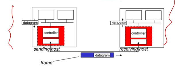
Two NIC’s/ adapters
Sending side:
Encapsulates datagram in frame
Adds error checking bits, rdt, flow control, etc
Receiving side:
Looks for errors, rdt, flow control, etc
Extracts datagram, passes to upper layer at receiving side
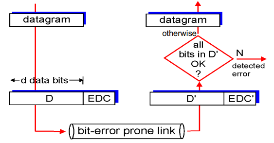
Error Detection
EDC = Error Detection and Correction bits (redundancy)
D = Data protected by error checking, may include header fields
Error detection not 100% reliable!
May miss some errors
Larger EDC field yields better detection and correction
Parity Checking
Single Bit Parity
Detects single bit errors
Only used in cases that there are very few errors in transmission
One redundancy (parity) bit added
Two types:
Even parity = decide parity bit so total number of ones is even
Odd parity = decide parity bit so total number of ones is odd
Then we just check if the result has even/odd ones at the end for errors
Not perfect obviously, there might be two+ errors that make ti even, we can only detect any odd number of bit errors
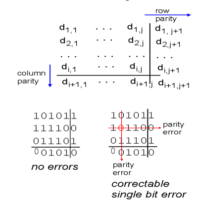
Two Dimension Bit Parity
Detects and CORRECTS single bit errors
Represent our data as an array of rows (as close to square as possible)
Give each row and every column a parity bit
Allows us to pinpoint and correct thee location of the error
Checksum review
Sender
Treat segment contents as sequence of 16 bit integers
checksum = 1’s complement of segments contents
Sender puts checksum value into UDP checksum field
Receiver
Compute checksum of received segment
Check if computed checksum = checksum field value
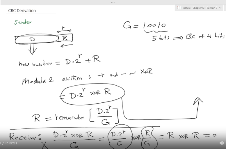
Cyclic redundancy check
More powerful error detection
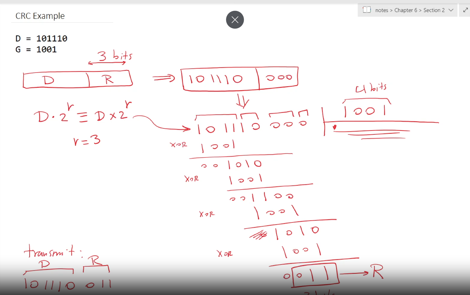
View data bits, D, as a binary number
choose r+1 bit pattern (generator), G
goal: choose r CRC bits, R, such that
<D,R> exactly divisible by G
receiver knows G, divides <D,R> by G. If non zero remainder, error detected!
Can detect all burst errors up to r bits
Widely used

Multiple Access Links, Protocols
Two types of “links”
Point to point
PPP for dial up access
Point to point link between ethernet switch and host
Broadcast 9shared wire or medium)
Upstream HFC
802.11 wireless LAN
Multiple access protocols
Single shared broadcast channel
two or more simultaneous transmissions by nodes: interference
Collision of node receives two or more signals at the same time
Multiple access protocols
Prevents multiple nodes from transmitting simultaneously over the shared broadcast channel
Determines how nodes share channel and when they can transmit
Challenging, because communication about channel sharing uses the channel itself!
An ideal multiple access protocol
Given = broadcast channel of rate R bps
Desired:
when M nodes are active, each can transmit at average rate R/M (fair sharing)
when only one node is active it can send at rate R (fully capacity, efficiency)
fully decentralized
No special node to coordinate transmissions
No synchronization of clocks, slots
Simple!
MAC protocols: taxonomy
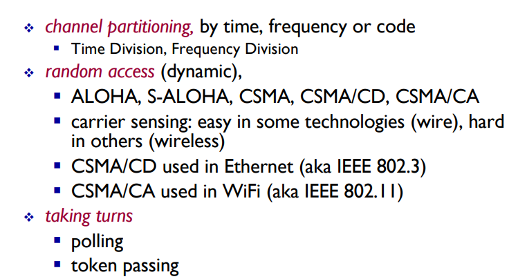
Three broad classes
channel partitioning
divides channel into smaller “pieces” (time slot, frequency")
allocate piece to node for exclusive use
No collision!
Random access
Channel not divided, allow collisions
“recover” from collisions
Taking turns
Nodes take turns, but nodes with more to send can take longer turns
Channel Partitioning MAC protocols: TDMA
TDMA = time division multiple access
Each station gets fixed length slot (length = packet trans time) in each round
unused slots go idle
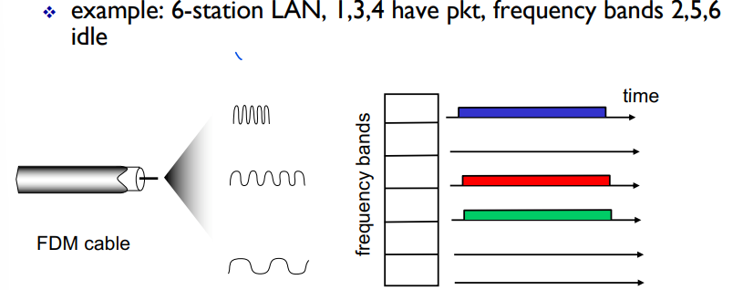
E.g 6 station LAN, 1,3,4 have pkt, slots 2,5,6 idle

Channel partitioning MAC protocols: FDMA
FDMA = frequency division multiple access
Each sectrum divided into frequency bands
Each station gets assigned fixed frequency band
unused transmission time in frequency bands go idle
Random Access Protocols
When node has packet to send
Transmit at full channel data rate R
no prior coordination among nodes
Two or more transmitting nodes => Collision
Random access MAC protocol specifies
Detecting collisions
Recovering from collisions (e.g via delayed transmission - random delay which prevents sending at the same time)
Examples of random access MAC protocols
Slotted ALOHA
ALOHA
CSMA, CSMA/CD, CSMA/CA
ALOHA
Very simple
A user transmits at will (random access)
If two or more messages overlap in time, there is a collision
Sender waits for roundtrip time plus a fixed delay
Lack of ACK = collision
After a collision, colliding stations retransmit the packet, but they stagger their attempts randomly to reduce the chance of repeated collisions
Slotted ALOHA
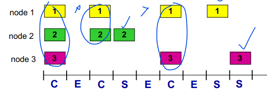
Assumptions:
All frames same size
time divided into equal size slots (time to transmit 1 frame)
Nodes start to transmit only at slot beginning
Nodes are synchronized
If 2 or more nodes transmit in slot, all nodes detect collision
Operation:
When node obtains fresh frame, transmits in next slot
If no collision: node can send new frame in next slot
If collision: Node retransmits frame in each subsequent slot with probability p until success
Pros:
Single active node can continuously transmit at full rate of channel
highly decentralized, only slots in nodes need to be in sync
simpel
Cons:
Collisions waste slots
idl slots
nodes may be able to detect collision in less time to transmit packet
clock synchroniztion
Slotted ALOHA: Efficiency
Efficiency = # of successful time slots / total number of time slots

= Probability a given ts is successful

E = efficiency of slotted ALOHA
R = capacity of shared channel
Suppose: N nodes with many frames to send, each transmits in slot with probability P
Prob that given node has success in a slot = P(1-P)^N-1
prob that any node has a success = NP(1-P)^N-1
Max efficiency: find p that maximizes that ^
for many nodes, take limit of NP*(1-P*)N-1 as N goes to infinity gives:
Max effiency = 1/e = 0.37 = Max effiency of 37%!!!
Pure (unslotted) ALOHA
Unslotted ALOHA = simpler, no synchronization
When frame arrives, transmit immediately
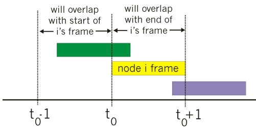
Collision probability increases:
Frame sent at t0 collides with other frames sent in [t0-1, t0+1]
ALOHA Effiency = 0.18 = 18% = worse than Slotted ALOHA!!!
CSMA (carrier sense multiple access)
CSMA = listen before transmit
If channel sensed idle: transmit entire frame
If channel sensed busy: defer transmission
Human analogy = don’t interupt others!
CSMA Collisions
Collisions can still occur:
Propagation delay means two nodes may not hear eachother’s transmission
Collision = entire packet transmision time wasted!
CSMA/CD (Collision detection)
CSMA/CD = carrier sensing, deferral as in CSMA
Collisions detected within short time
colliding transmissions aborted, reducing channel wastage!
Collision detection:
Easy in wired LANs: measure signal strengths, compare transmitted, received signals
Difficult in wireless LANs: received signal strength overwhelmed by local transmission length
CSMA/CD Effiency
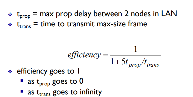
Better than ALOHA! And simple and cheap and decentralized!
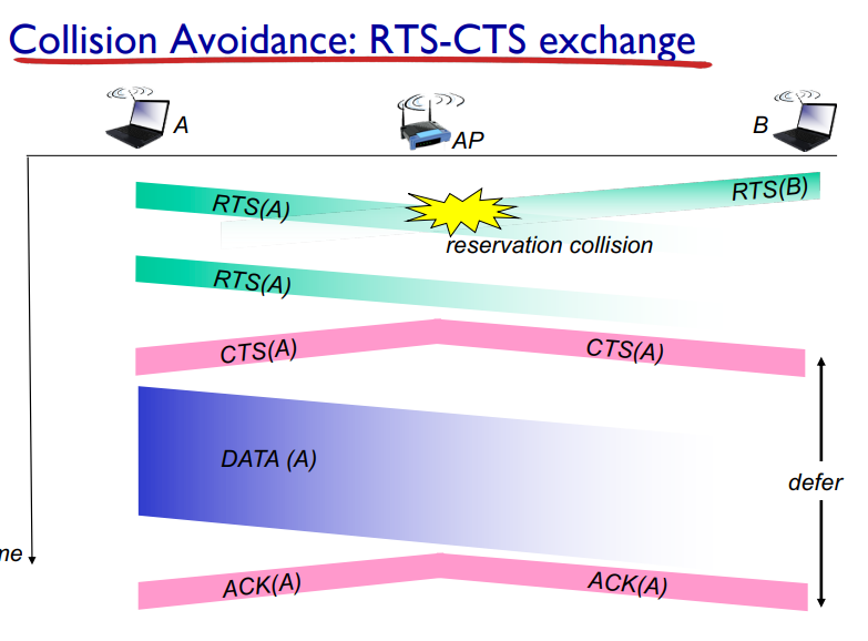
CSMA/CA (Collision Avoidance)
allows sender to reserve channnel rather than random access of data frames: avoid collisions of long data frames
Sender first transmits small request to send (RTS) packets to receiver using CSMA
RTSs may still collide with eachother (but they’re short)
Receiver broadcasts clear to send CTS in response to RTS
CTS heard by all nodes
Sender transmits data frame
other nodes defer transmissions
Avoid data frame collisions using small reservation packeets!
Taking Turns MAC Protocols
Channel partitioning MAC protocols
Share channel efficiently and fairly at high load
Inefficient at low load, delay in channel access, 1/N bandwidth allocated even if only 1 active node!
Random access MAC protocols
Efficient at low load: single node can fully utilize channel
High load; collision overhead
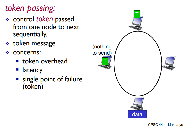
Taking turns protocols
Best of both worlds!
Taking Turns MAC protocol
Polling
Master node “invites” slave nodes to transmit in term
typically used with ‘dumb” slave devices
Concerns:
Polling overhead
Latency
Single point of failure (master)
Used in bluetooth networks
Summary of MAC protocols
MAC Addresses and ARP
32 Bit IP address
Network layer address for interface
Used for forwarding
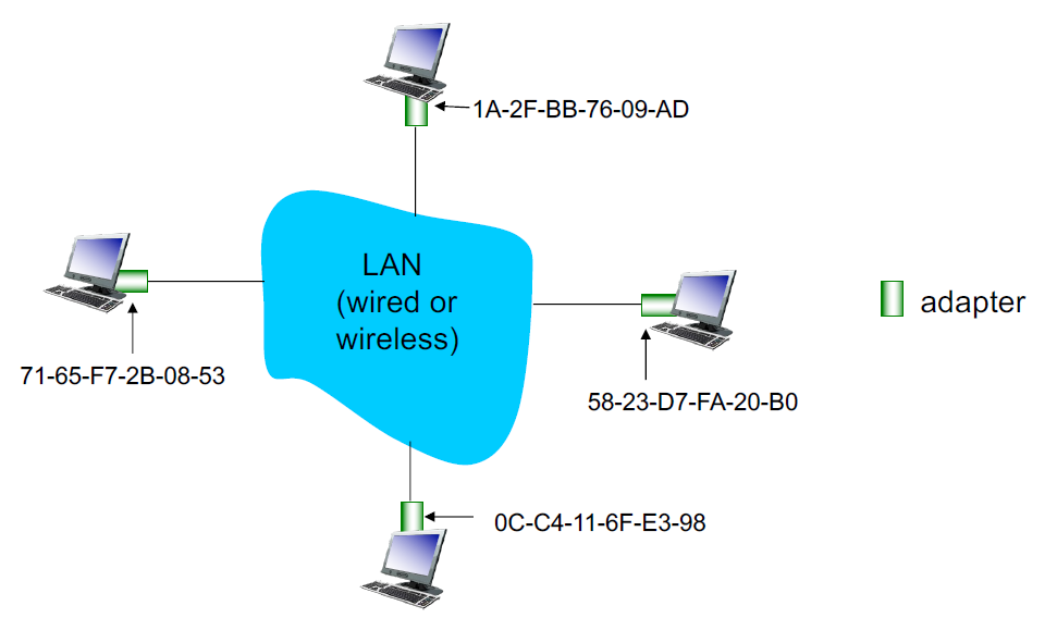
MAC (or LAN or Physical or Ethernet) address
Used “locally” to get frame from one interface to another physically-connected interface (same network in IP addressing sense)
48 bit MAC address burned into NIC ROM
Each adapter on LAN has a unique LAN address
LAN addresses (more)
MAC/LAN address allocation administerd by IEEE
manufacturer buys portion of MAC address space (to assure uniqueness)
Anology
MAC address = like social insurance number
IP address = like postal address
MAC flat address → portiability
Can move LAN card from one LAN to another
IP heirarchical address not portable
address depends on IP subnet to which node is attached
ARP: Address Resolution Protocol
How to determine an interface’s MAC address knowing its IP address?
ARP table = each IP node (host, router) on LAN has a table
IP/MAC address mappings for some LAN nodes <IP address; MAC address; TTL>
TTL = Time To Live = time after which address mapping will be forgotten
ARP Protocol: Same LAN
A wants to send datagram to B
B’s MAC address not in A’s ARP table
A broadcasts ARP query packet, containing B’s IP address
dest MAC address = FF-FF-FF-FF-FF-FF (the broadcast MAC address)
all nodes on LAN receive ARP query
B receives ARP packet, replies to A with its (B’s) MAC address
Frame sent to A’s MAC address (unicast)
A caches (saves) IP-to-MAC address pair in its ARP table until the info times out
Soft state =info that times out unless refreshed
ARP is “plug and play”
Nodes create their ARP tables without intervention from net admin
Addressing: routing to another LAN
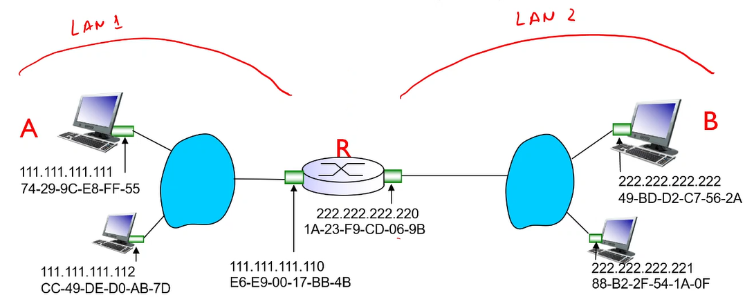
walkthrough : send datagram from A to B via R
Focus on addressing - at IP (datagram) and MAC layer (frame)
Assume A knows B’s IP address
assume A knows IP address of first hop router, R (DHCP, otherwise, this address would have to be manually configured)
assume A knows R’s MAC address (local ARP)
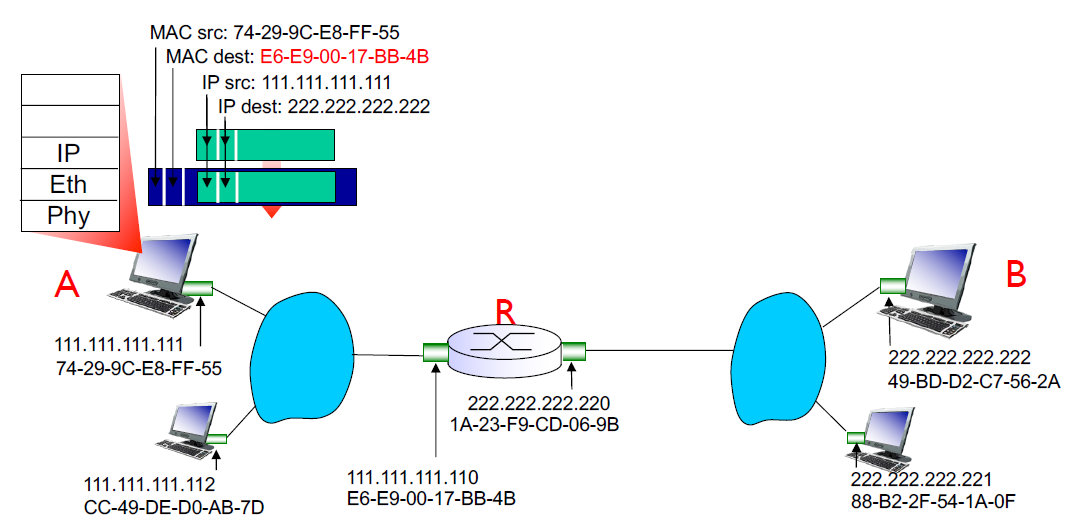
A creates IP datagram with IP source A, destination B
A creates link layer frame with R’s MAC address as destination, frame contains A to B IP datagram
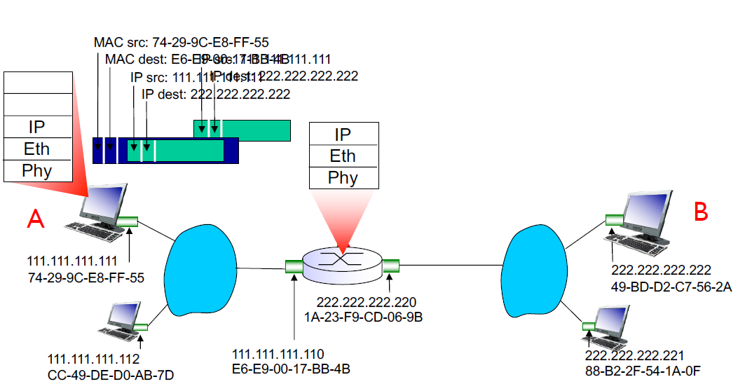
Frame is sent from A to R
Frame is received at R and the datagram is removed and passed up to IP
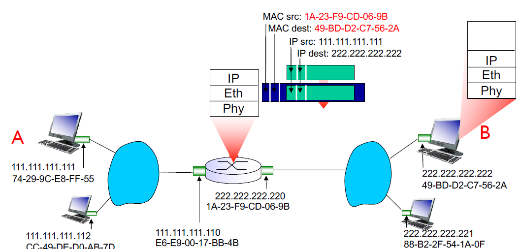
R forwards datagram with source A destination B to its proper link (using forwarding table)
R creates link layer frame with B’s MAC address as destination, frame contains A-to-B IP datagram
Ethernet
Dominant wired LAN technology
Low cost NIC
first widely used LAN technology
speedy
MAC protocol = CSMA/CD
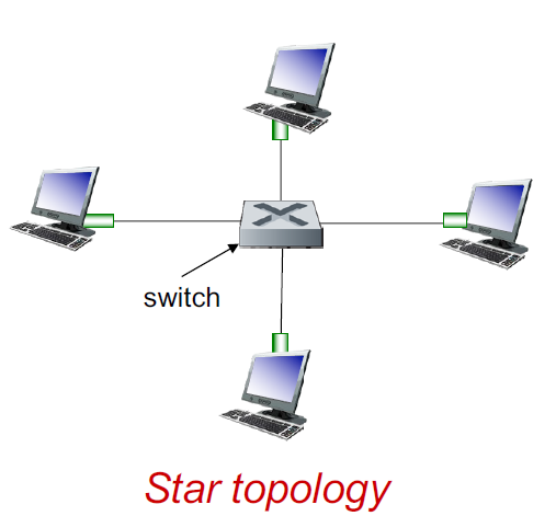
Ethernet: physical topology
Active switch in center
Like a router but only implements the switching part
each “spoke” runs a separate Ethernet protocol (nodes do not collide with each other)
Because only one node conncted to each link, no collisions
Ethernet Frame Structure
Sending adapter encapsulates IP datagram into an Ethernet frame

preamble:
7 bytes with pattern 10101010 followed by one byte with the pattern 10101011
Used to synchronize receiver, sender clock rates
Sender first transmits this known pattern, so that things can synch in the receiver
Payload=single datagram (IP or whatever protocol)
addresses: 6 byte source, destination MAC addresses
If adapter receives frame with matching destination address, or with broadcast address (e.g ARP packet) it passes data in frame to network layer protocol
Otherwise, it discards it
Type = indicates higher layer protocol (mostly IP)
CRC = cyclic redundancy check at receiver
Ethernet: Unreliable, connectionless
Connectionless: No handshaking between sending and receiving NICs
Unreliable: receiving NIC doesn’t send ACKs or NACKs to sending NIC
Data in dropped frames only recovered if initial sender uses higher layer rdt (e.g TCP)
Ethernet’s MAC protocol: unslotted CSMA/CD with binary backoff
No synchronization
Binary backoff = randomizing retransmissions
When the first collision happens, the contention window is [0,1], the node randomly picks a digit k from this window. then waits K x unit of time before retransmitting
Afterwards, contention window increases exponentially, 2^(collision number), e.g for the second collision itll be [0,1,2,3]
The more collisions, longer backoff interval
Ethernet CSMA/CD algorithm
NIC receives datagram from network layer, creates frame
If NIC senses channel idle, starts frame transmission. If NIC senses channel busy, waits until idle then transmits
If NIC transmits entire frame without detecting another transmission, NIC is done wtih frame!
If NIC detects another transmission while transmitting, aborts and sends jam signal
After aborting, NIC enters binary exponential backoff
802.3 Ethernet standards: link and physical layers
Many different Ethernet standards
Common MAC protocol and frame format
different speeds
different physical layer media: fiber, cable
Ethernet Switch
Link layer device: takes and active role
Store, forward Ethernet frames
examine incoming frame’s MAC address, selectively forward frame to one-or-more outgoing links when frame is to be forwarded on segment, uses CSMA/CD to access segment
Transparent
Hosts are unaware of presence of switches, as if they’re directly connected to eachther
Plug-and-play, self learning
Switches don’t need to be configured
Switch: Multiple simultaneous transmissions
hosts have direct connection to switch
switch buffers packets
Ethernet protocol used on each incoming link, but no collisions, (full duplex)
Each link is its own collision domain
A to A’ and B to B’ can transmit simultaneously with no collisions!

This is a LAN ^
Switch Forwarding Table
How does switch know A’ is reachable via interface 4, and B’ is reachable by interface 5?
Each switch has a switch table! Eache entry”
MAC address of host, interface to reach host, time stamp (TTL)
Looks like a routing table!
Switch: Self Learning
How are entries created and maintained in the switch table?
The switch learns which hosts can be reached through which interfaces
When a frame is received, the switch “learns” the location of the sender: incoming LAN segment
Records sender/location pair in switch table
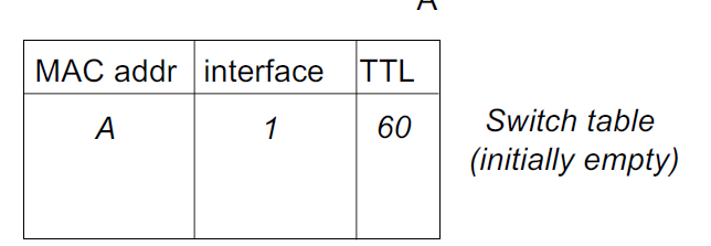
A → A’ from 1, now we know how to get to A!
Self-learning: flooding
Frame destination, A’, location unknown: flood!
Flood = forwards it over all its interfaces (except source)
Destination A location known:
Selective forwarding
In the future A’ will send something, so we’ll add it to a table
Basically:
We know where it is? selective forward
We dont? Flood
Interconnecting switches
Switches can be connected together
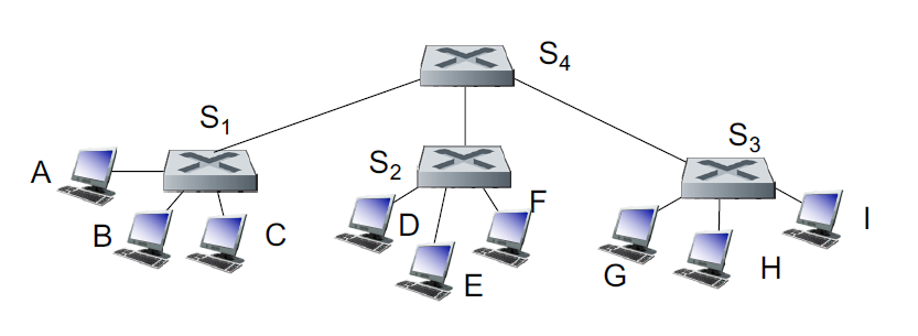
If we want to send from A to G, how does S1 know how to forward frame destined to G via S4 and S3
Self learning! Same as single switch
But flooding is slower ☹
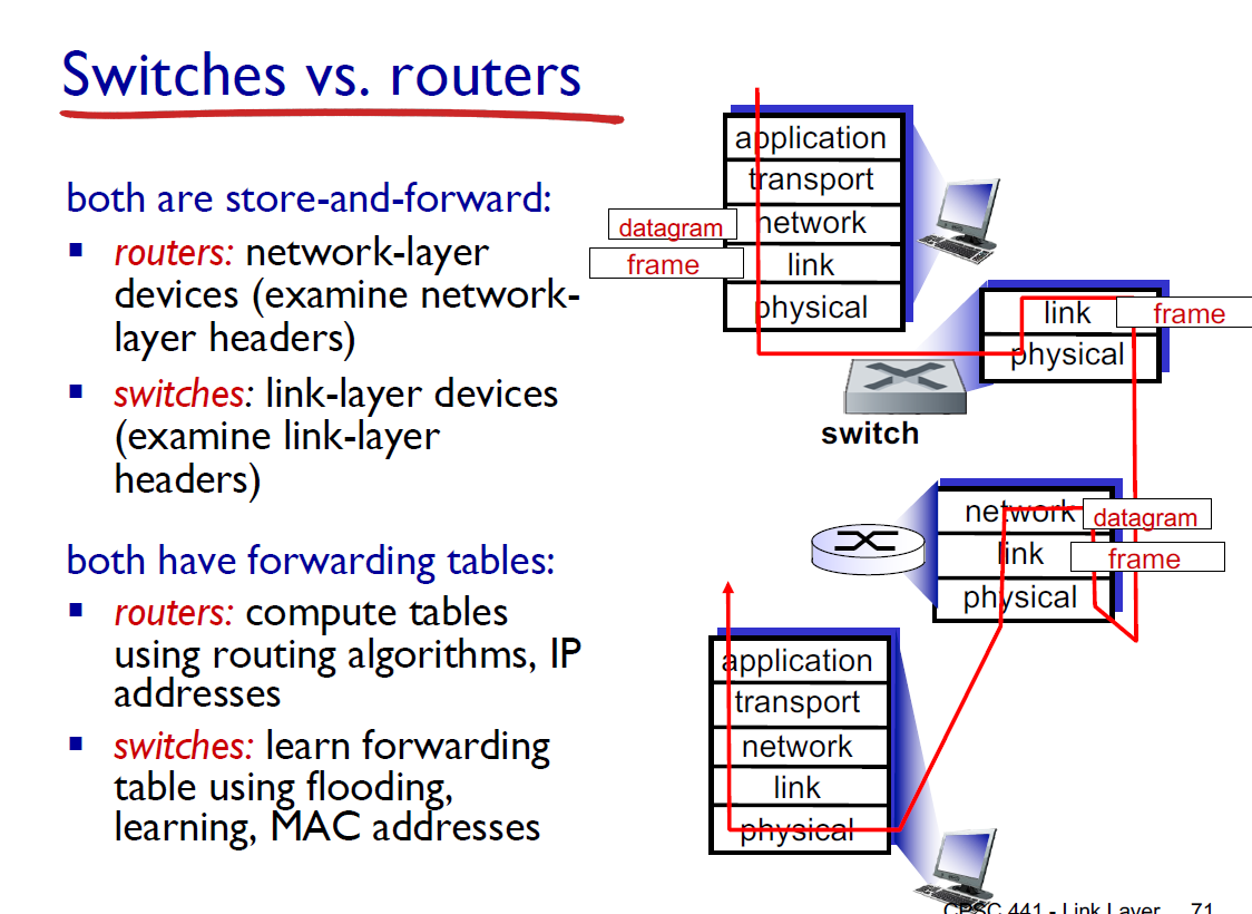
Routers = network layer
Switches = Link layer
Routers = compute tables using routing algorithms, use IP addresses
Switches = learn forwarding table with self learning, MAC addresses
Switches = faster, but dumber!