Quiz 3-AirSysLec
Landing Gear (ATA 32)
PURPOSE OF LANDING GEAR
Structural Support: Landing gear provides essential structural support to the aircraft during ground operations.
Maneuverability: It facilitates the aircraft's maneuverability on the ground, enabling it to taxi, turn, and park.
Load Absorption: Landing gear serves as a means to absorb and distribute unusual loads experienced during landing and ground operations, ensuring safety and stability.
DESIGN CONSIDERATIONS
Maximum strength
Minimum weight
High reliability
Low cost
Airfield compatibility
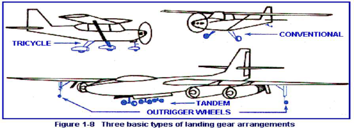
3 COMMON LANDING GEAR ARRANGEMENTS
Tail Wheel (Conventional Gear): Main gear forward, requiring a tailwheel for support.
Tandem Gear: Main and tail gear aligned along the aircraft's longitudinal axis (rare).
Tricycle Gear: Main gear behind the center of gravity, nose gear at the front (common in modern aircraft).

TWO CATEGORIES OF LANDING GEAR
Fixed Gear: Remains exposed to slipstream, causes parasite drag.
Retractable Gear: Stows in fuselage/wing compartments, reduces parasite drag during flight.
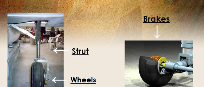
THREE MAIN PARTS OF LANDING GEAR
strut
wheels
brake

4 TYPES OF LANDING GEAR STRUTS
Leaf Spring Gear: Utilizes flexible spring materials to absorb and dissipate landing impact gradually.
Rigid Gear: Early aircraft used welded steel struts that directly transferred shock loads to the airframe, often with pneumatic tires for cushioning.
Bungee Cord: Struts flex upon landing impact, with bungee cords absorbing and gradually releasing loads to the airframe.
Shock Struts (Air/Oil or Oleo Struts): Self-contained hydraulic units using air or nitrogen combined with hydraulic fluid to absorb and dissipate shock loads during landing.
AIRCRAFT BRAKES
Brakes slow and stop aircraft, hold it during engine run-up, and aid in taxiing.
Typically, main wheels have brakes; nose/tail wheels do not.
4 COMMON AIRCRAFT BRAKE TYPES
Single Disc Brake: Floating-disc, fixed caliper brake.
Dual and Multiple Disc Brake: Heavy-duty, used with power brake control valves or boost master cylinders.
Segmented Rotor-Disc Brake: Multiple-disc brake with segmented rotors for improved cooling and prolonged braking.
Carbon Brake: Utilizes pure carbon discs, offering weight savings and effective heat dissipation, eliminating extended cooling periods.
AIRCRAFT TIRES AND TUBES
2 TYPES OF TIRE CLASSIFICATION
Tubeless: These tires have an inner liner approximately one-tenth of an inch thick, serving as an air container.
Tubed: Tube-type tires lack this liner but have a smoother inside to protect the tube from chafing.
TYPES OF TIRES
The United States Tire and Rim Association recognizes 9 types of aircraft tires, with 3 being of primary concern:
Type III: The most popular low-pressure tire.
Type VII: Extra-high-pressure tires, standard for jet aircraft.
Type VIII: Used for high-performance jet aircraft with extremely high takeoff speeds. They feature extra-high inflation pressure and a low profile.
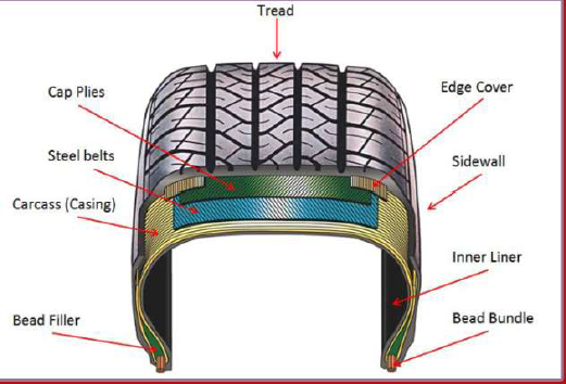
TIRE CONSTRUCTION
Bead: Tire edge on the wheel.
Carcass: Layer above the inner liner with textile fiber cords.
Tread: The rubber that contacts the road.
Sidewall: Protects cords, displays tire info.

INFLATION
Heat is aircraft tire's enemy.
Designed to withstand heat from flexing.
Inflation pressure critical, check daily and before flight.
Remove if tread is cut over half a rib width.
HYDROPLANING
occurs when water builds between vehicle wheels and the road, leading to a loss of traction, making the vehicle unresponsive to control inputs.

Fuel System(ATA 28)
AIRCRAFT FUEL
Aviation Fuel: A liquid containing chemical energy, released as heat energy through combustion and converted to mechanical energy by the engine.
Fuel Source: Aircraft engine fuels are petroleum products derived from crude oil by refineries, classified as inflammable liquids.
PROPERTIES OF FUEL
Volatility: Ability to change from liquid to vapor.
Flash Point: Temperature for ignition with an external heat source.
Fire Point: Temperature for continued burning without external source.
Viscosity: Internal resistance to flow.
Freezing Point: Temperature where solid particles form.
Vapor Lock: AVGAS vaporizes in the fuel line or components between the fuel line and carburetor.
TYPES OF FUEL SYSTEM
1. Gravity Feed Systems: Utilize gravity to transfer fuel from the tanks to the engine.
2. Pump Feed/Fuel Pump Systems: Require a fuel pump to provide fuel pressure for transfer.
FUEL SYSTEM COMPONENTS
Tanks: Manufactured from non-reactive materials, with common features including a sump, drain, and top vent to the atmosphere. Some tanks have dump valves for in-flight fuel jettison.
4 Common Types of Tanks
Rigid Removable Tanks: Older aircraft use welded or riveted gasoline tanks, now largely replaced by integral or bladder-type tanks. Smaller tanks are made of terneplate, a lead-tin alloy-coated thin sheet steel.
Integral Fuel Tanks: Maximize fuel storage in minimal space with low weight. Common in light aircraft, they occupy the leading-edge portion of the wing, sealed with a two-part sealant.
Bladder Tanks: Prepare the fuel bay with chafe-resistant tape on metal edges and install a bladder made of thin, neoprene-impregnated fabric that is fuel-resistant.
Surge Tanks: Not counted in the aircraft's fuel capacity, they serve as a precaution in case main tanks overflow.
Fuel Pumps: Engine-driven fuel pumps deliver properly pressured, continuous fuel supply during engine operation. Auxiliary fuel pumps can assist in engine starting and maintain positive pressure at the engine-driven fuel pump inlet.
2 TYPES OF FUEL PUMPS
Hand-Operated Pumps (Wobble Pumps): Used to back up engine-driven pumps and transfer fuel between tanks.
Centrifugal Boost Pump: Popular auxiliary pump driven by an electric motor, installed inside or outside the fuel tank. It uses an impeller to propel fuel into the discharge line.
FUEL INJECTORS
Description: A specific area in the fuel tank partitioned with a flapper-type valve allowing fuel flow into the collector from the tank.
Operation: Utilizes a fuel ejector system based on the venturi principle, providing additional fuel to the collector can regardless of the aircraft's attitude.
FUEL VALVES
Function: Selector valves are installed in the fuel system to control fuel flow, tank and engine selection, cross-feed, and fuel transfer.
Variation: The size and number of ports (openings) differ according to the specific installation.
FILTERS
Importance: Crucial to ensure contamination-free fuel supply for aircraft engines.
Components: Every aircraft fuel system includes a series of strainers and filters.
Sampling: Provision for draining fuel samples from all tanks and from the main strainer must be present.
FUEL LINES AND FITTINGS
Materials: Metal tubing is typically aluminum alloy, while flexible hoses are made from synthetic rubber or Teflon.
Diameter: Tubing diameter is determined by the engine's fuel flow requirements.
Material Type: Most rigid fuel lines used in aircraft are constructed from 5052 aluminum alloy.
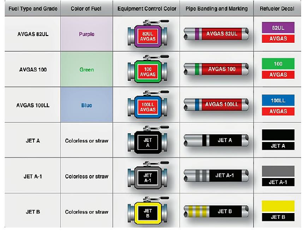
FUEL GRADES
Definition: Aviation gasoline (AVGAS) is categorized by an octane or performance number (grade) that indicates its antiknock value or knock resistance within the engine cylinder.
Higher Grade: Higher-grade gasoline can withstand more pressure without detonation.

AIRCRAFT REFUELING AND FUELING
Two Processes:
Over the Wing Refueling: Aircraft are typically refueled over the wing, and the fuel is drained through the tank sump drain.
Pressure Refueling: Pressure-fueled aircraft are usually defueled through the pressure fueling port.
VENT SYSTEM
Fuel Vent: Small pipe for pressure equalization between the tank and the outside.
FUEL DUMPING
Fuel Dumping/Jettison: Used in emergencies after takeoff or before landing to reduce aircraft weight.
FUEL SYSTEM INDICATORS
Sight Glass: Clear tube open to the fuel tank, showing fuel level.
Digital Indicators: Converts resistance to a digital signal, displayed on a screen panel.
Fuel Temperature Gauge: Alerts pilot to approaching temperatures that could cause fuel system ice.
FUEL CONTAMINATION (most common forms)
Solid Contaminants: Non-dissolv moing particles in fuel, including rust, scale, sand, and dirt.
Surfactants: Soap or detergent-like substances occurring naturally or introduced during refining/handling.
Microorganisms: Over 100 varieties can thrive in free water within fuel systems. Airborne microorganisms constantly expose fuel to contamination. Effects include sludge formation, emulsification, corrosion, and odors.
Quiz 3-AirSysLec
Landing Gear (ATA 32)
PURPOSE OF LANDING GEAR
Structural Support: Landing gear provides essential structural support to the aircraft during ground operations.
Maneuverability: It facilitates the aircraft's maneuverability on the ground, enabling it to taxi, turn, and park.
Load Absorption: Landing gear serves as a means to absorb and distribute unusual loads experienced during landing and ground operations, ensuring safety and stability.
DESIGN CONSIDERATIONS
Maximum strength
Minimum weight
High reliability
Low cost
Airfield compatibility
3 COMMON LANDING GEAR ARRANGEMENTS
Tail Wheel (Conventional Gear): Main gear forward, requiring a tailwheel for support.
Tandem Gear: Main and tail gear aligned along the aircraft's longitudinal axis (rare).
Tricycle Gear: Main gear behind the center of gravity, nose gear at the front (common in modern aircraft).

TWO CATEGORIES OF LANDING GEAR
Fixed Gear: Remains exposed to slipstream, causes parasite drag.
Retractable Gear: Stows in fuselage/wing compartments, reduces parasite drag during flight.
THREE MAIN PARTS OF LANDING GEAR
strut
wheels
brake

4 TYPES OF LANDING GEAR STRUTS
Leaf Spring Gear: Utilizes flexible spring materials to absorb and dissipate landing impact gradually.
Rigid Gear: Early aircraft used welded steel struts that directly transferred shock loads to the airframe, often with pneumatic tires for cushioning.
Bungee Cord: Struts flex upon landing impact, with bungee cords absorbing and gradually releasing loads to the airframe.
Shock Struts (Air/Oil or Oleo Struts): Self-contained hydraulic units using air or nitrogen combined with hydraulic fluid to absorb and dissipate shock loads during landing.
AIRCRAFT BRAKES
Brakes slow and stop aircraft, hold it during engine run-up, and aid in taxiing.
Typically, main wheels have brakes; nose/tail wheels do not.
4 COMMON AIRCRAFT BRAKE TYPES
Single Disc Brake: Floating-disc, fixed caliper brake.
Dual and Multiple Disc Brake: Heavy-duty, used with power brake control valves or boost master cylinders.
Segmented Rotor-Disc Brake: Multiple-disc brake with segmented rotors for improved cooling and prolonged braking.
Carbon Brake: Utilizes pure carbon discs, offering weight savings and effective heat dissipation, eliminating extended cooling periods.
AIRCRAFT TIRES AND TUBES
2 TYPES OF TIRE CLASSIFICATION
Tubeless: These tires have an inner liner approximately one-tenth of an inch thick, serving as an air container.
Tubed: Tube-type tires lack this liner but have a smoother inside to protect the tube from chafing.
TYPES OF TIRES
The United States Tire and Rim Association recognizes 9 types of aircraft tires, with 3 being of primary concern:
Type III: The most popular low-pressure tire.
Type VII: Extra-high-pressure tires, standard for jet aircraft.
Type VIII: Used for high-performance jet aircraft with extremely high takeoff speeds. They feature extra-high inflation pressure and a low profile.
TIRE CONSTRUCTION
Bead: Tire edge on the wheel.
Carcass: Layer above the inner liner with textile fiber cords.
Tread: The rubber that contacts the road.
Sidewall: Protects cords, displays tire info.

INFLATION
Heat is aircraft tire's enemy.
Designed to withstand heat from flexing.
Inflation pressure critical, check daily and before flight.
Remove if tread is cut over half a rib width.
HYDROPLANING
occurs when water builds between vehicle wheels and the road, leading to a loss of traction, making the vehicle unresponsive to control inputs.

Fuel System(ATA 28)
AIRCRAFT FUEL
Aviation Fuel: A liquid containing chemical energy, released as heat energy through combustion and converted to mechanical energy by the engine.
Fuel Source: Aircraft engine fuels are petroleum products derived from crude oil by refineries, classified as inflammable liquids.
PROPERTIES OF FUEL
Volatility: Ability to change from liquid to vapor.
Flash Point: Temperature for ignition with an external heat source.
Fire Point: Temperature for continued burning without external source.
Viscosity: Internal resistance to flow.
Freezing Point: Temperature where solid particles form.
Vapor Lock: AVGAS vaporizes in the fuel line or components between the fuel line and carburetor.
TYPES OF FUEL SYSTEM
1. Gravity Feed Systems: Utilize gravity to transfer fuel from the tanks to the engine.
2. Pump Feed/Fuel Pump Systems: Require a fuel pump to provide fuel pressure for transfer.
FUEL SYSTEM COMPONENTS
Tanks: Manufactured from non-reactive materials, with common features including a sump, drain, and top vent to the atmosphere. Some tanks have dump valves for in-flight fuel jettison.
4 Common Types of Tanks
Rigid Removable Tanks: Older aircraft use welded or riveted gasoline tanks, now largely replaced by integral or bladder-type tanks. Smaller tanks are made of terneplate, a lead-tin alloy-coated thin sheet steel.
Integral Fuel Tanks: Maximize fuel storage in minimal space with low weight. Common in light aircraft, they occupy the leading-edge portion of the wing, sealed with a two-part sealant.
Bladder Tanks: Prepare the fuel bay with chafe-resistant tape on metal edges and install a bladder made of thin, neoprene-impregnated fabric that is fuel-resistant.
Surge Tanks: Not counted in the aircraft's fuel capacity, they serve as a precaution in case main tanks overflow.
Fuel Pumps: Engine-driven fuel pumps deliver properly pressured, continuous fuel supply during engine operation. Auxiliary fuel pumps can assist in engine starting and maintain positive pressure at the engine-driven fuel pump inlet.
2 TYPES OF FUEL PUMPS
Hand-Operated Pumps (Wobble Pumps): Used to back up engine-driven pumps and transfer fuel between tanks.
Centrifugal Boost Pump: Popular auxiliary pump driven by an electric motor, installed inside or outside the fuel tank. It uses an impeller to propel fuel into the discharge line.
FUEL INJECTORS
Description: A specific area in the fuel tank partitioned with a flapper-type valve allowing fuel flow into the collector from the tank.
Operation: Utilizes a fuel ejector system based on the venturi principle, providing additional fuel to the collector can regardless of the aircraft's attitude.
FUEL VALVES
Function: Selector valves are installed in the fuel system to control fuel flow, tank and engine selection, cross-feed, and fuel transfer.
Variation: The size and number of ports (openings) differ according to the specific installation.
FILTERS
Importance: Crucial to ensure contamination-free fuel supply for aircraft engines.
Components: Every aircraft fuel system includes a series of strainers and filters.
Sampling: Provision for draining fuel samples from all tanks and from the main strainer must be present.
FUEL LINES AND FITTINGS
Materials: Metal tubing is typically aluminum alloy, while flexible hoses are made from synthetic rubber or Teflon.
Diameter: Tubing diameter is determined by the engine's fuel flow requirements.
Material Type: Most rigid fuel lines used in aircraft are constructed from 5052 aluminum alloy.
FUEL GRADES
Definition: Aviation gasoline (AVGAS) is categorized by an octane or performance number (grade) that indicates its antiknock value or knock resistance within the engine cylinder.
Higher Grade: Higher-grade gasoline can withstand more pressure without detonation.

AIRCRAFT REFUELING AND FUELING
Two Processes:
Over the Wing Refueling: Aircraft are typically refueled over the wing, and the fuel is drained through the tank sump drain.
Pressure Refueling: Pressure-fueled aircraft are usually defueled through the pressure fueling port.
VENT SYSTEM
Fuel Vent: Small pipe for pressure equalization between the tank and the outside.
FUEL DUMPING
Fuel Dumping/Jettison: Used in emergencies after takeoff or before landing to reduce aircraft weight.
FUEL SYSTEM INDICATORS
Sight Glass: Clear tube open to the fuel tank, showing fuel level.
Digital Indicators: Converts resistance to a digital signal, displayed on a screen panel.
Fuel Temperature Gauge: Alerts pilot to approaching temperatures that could cause fuel system ice.
FUEL CONTAMINATION (most common forms)
Solid Contaminants: Non-dissolv moing particles in fuel, including rust, scale, sand, and dirt.
Surfactants: Soap or detergent-like substances occurring naturally or introduced during refining/handling.
Microorganisms: Over 100 varieties can thrive in free water within fuel systems. Airborne microorganisms constantly expose fuel to contamination. Effects include sludge formation, emulsification, corrosion, and odors.
 Knowt
Knowt