Magnetism + Electromagnetism
Magnetic flux density (strength of a magnetic field) is measured in Teslas (T)
Magnetically hard: materials that stay magnetic (iron alloys/ferrous metals). They produce a magnetic field which cannot be turned off.
Magnetically soft/induced magnets: materials that only become magnetic when it is placed in a magnetic field.
Typical magnetically hard materials: alloys of iron, nickel, cobalt (eg. steel).
The metallic core of the earth is permanently magnetic, as it contains lots of iron.
Plotting Magnetic Fields
Plotting compasses:
- Place a bar magnet in the centre of a sheet of paper, and draw a rectangle around it so you can be sure it doesn’t move place.
- Select a starting point close to a pole and mark a dot at both ends of the compass needle.
- Move the plotting compass around, making a dot adjacent to each end of the compass needle. Do this several times.
- Gradually, a line of force can be drawn by joining up the points all the way around from one end to the other end of the bar magnet. This shows the magnetic field lines produced by the bar magnet.
Seeing the pattern with Iron Filings:
- Place a permanent bar magnet under a sheet of paper.
- Sprinkle iron filings randomly on top of the paper.
- Tap the sheet repeatedly and gently until the pattern of the magnetic field emerges
-→ The permanent magnet induces magnetism in the iron filings and converts them into temporary magnets which all line up along the lines of force of the magnetic flux.
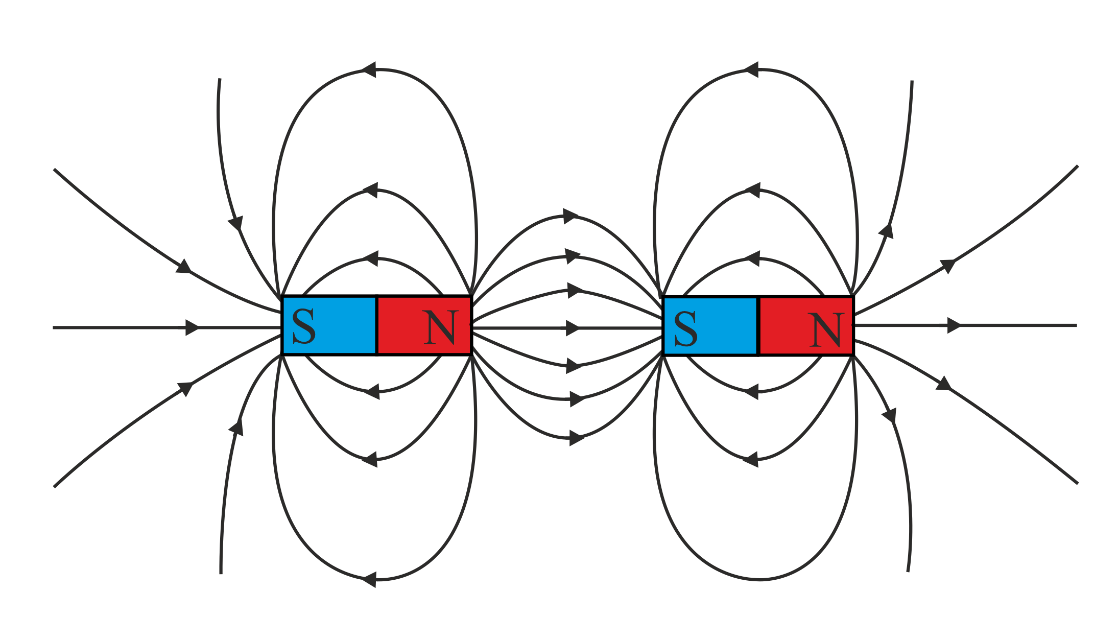
How to plot the magnet field of a bar magnet:
- Lines of force run from North pole to South pole
- The closer together the lines of force are, the stronger the magnetic field
- The lines of force cannot overlap
- The further away you get from a magnet, the weaker the magnetic field.
- The magnetic strength is strongest closest to the poles.
Induced magnetism: a permanent magnet induces the opposite poles of the magnetisable material causing attraction.
Electromagnets
When a current flows through a wire (or any conductor), a magnetic field is created around the wire.
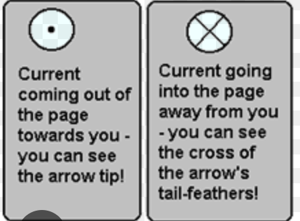
This field can be imagined as a series of concentric circles perpendicular to the wire.
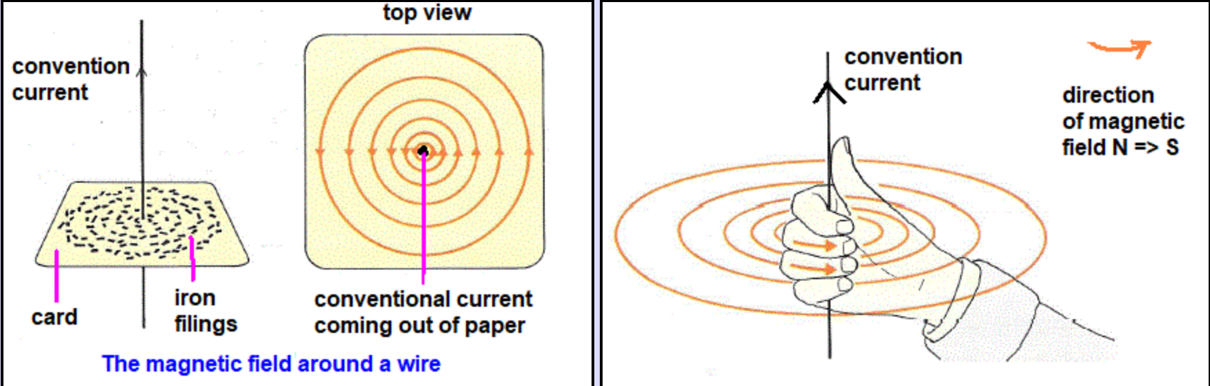 Use @@Fleming’s Right Hand Rule@@ to work out the direction of the magnetic field.
- Reversing the direction of current flow, reverses the direction of the magnetic field.
- The strength of the magnetic field is increased overall by increasing the current.
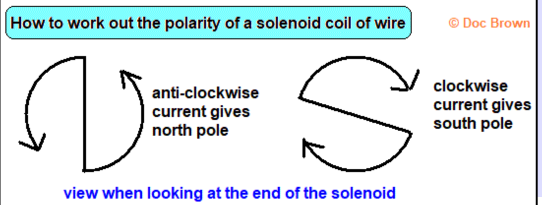
Solenoids
 An effective solenoid needs to consist of hundreds of coils of finely wound insulated copper wire.
A solenoid acts as an electromagnet which can be switched on and off depending on whether current is flowing or not (it acts as a temporary magnet).
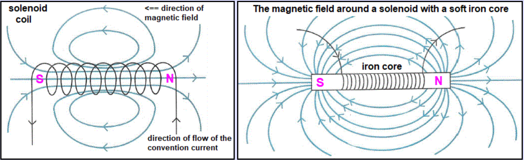
The increase in magnetic strength is due to all the lines of force lining up with each other and being close together too.
So, note the uniformity and intensity of the magnetic field inside the coil, which is much weaker outside the coil because lots of overlapping lines of force around each coil cancel each other out.
@@The magnetic field is overall weak, except at the ends of the solenoid where it is very strong.@@
 How to increase the magnetic field strength of a solenoid?
- Use a soft iron core -→ by placing a rod of magnetic material (e.g. iron) inside the solenoid, the iron becomes an induced magnet and the magnetic lines of force are intensified through it.
- Increase the current flow -→ the more charged particles flowing, the greater the magnetic field strength.
- Increasing the number of coils of wire
- If you can decrease the length of the solenoid but keep the same number of insulated coils of wire, you increase the intensity of the magnetic field.
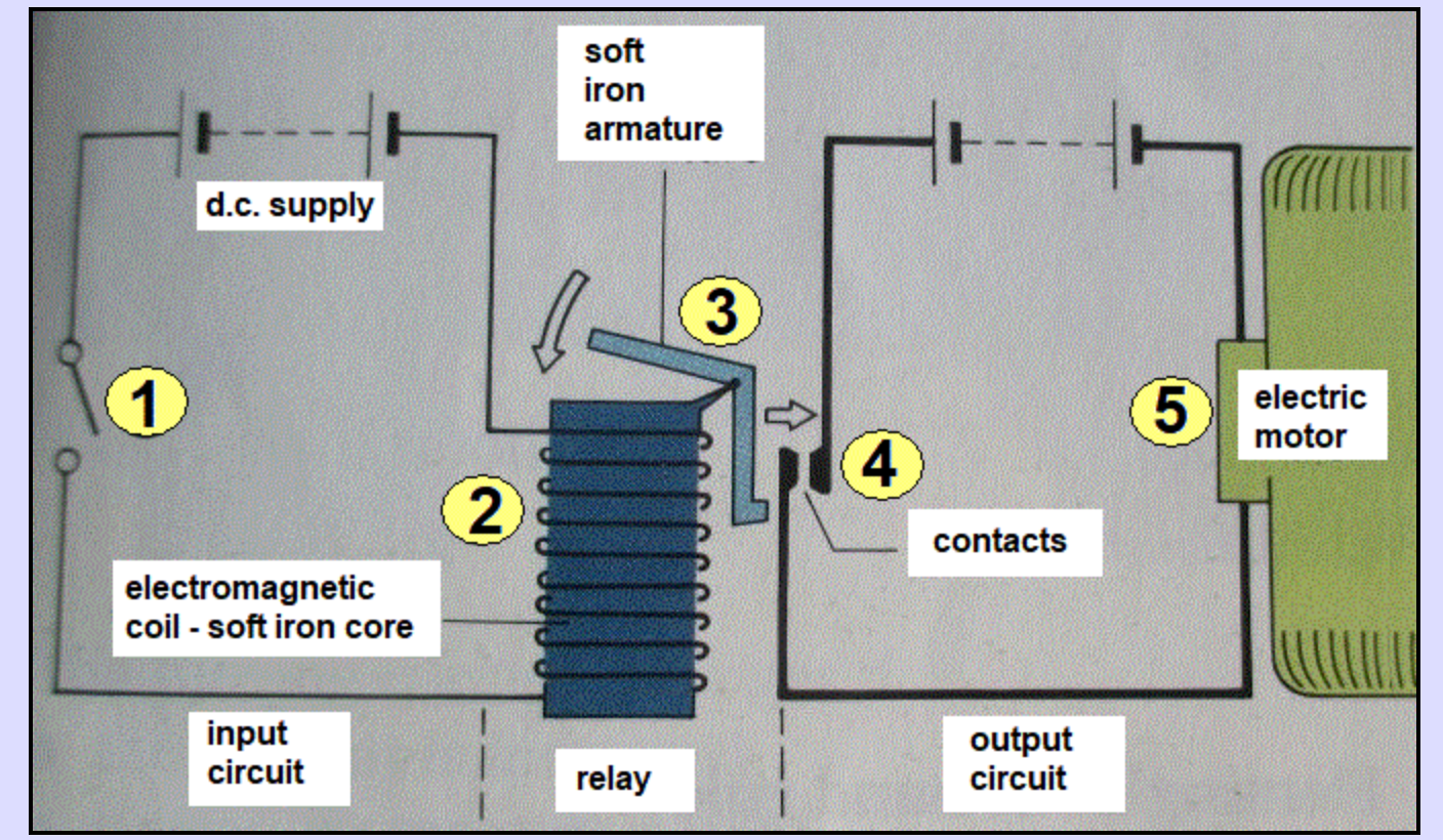
Relay Switch System
The Motor Effect - the interaction of two magnetic fields
When a current-carrying conductor (e.g. wire) is placed between the poles of a magnet, the magnetic field around the wire interacts with the magnetic field it is placed in. This interaction causes the conductor and magnet to exert a non-contact force on each other -- this force causes the wire to move and is known as the ‘motor effect’.
To get the maximum full force effect, the wire should be at 90 degrees to the direction of the magnetic field flux. If the wire is parallel to the magnetic field, it won’t experience a force at all.
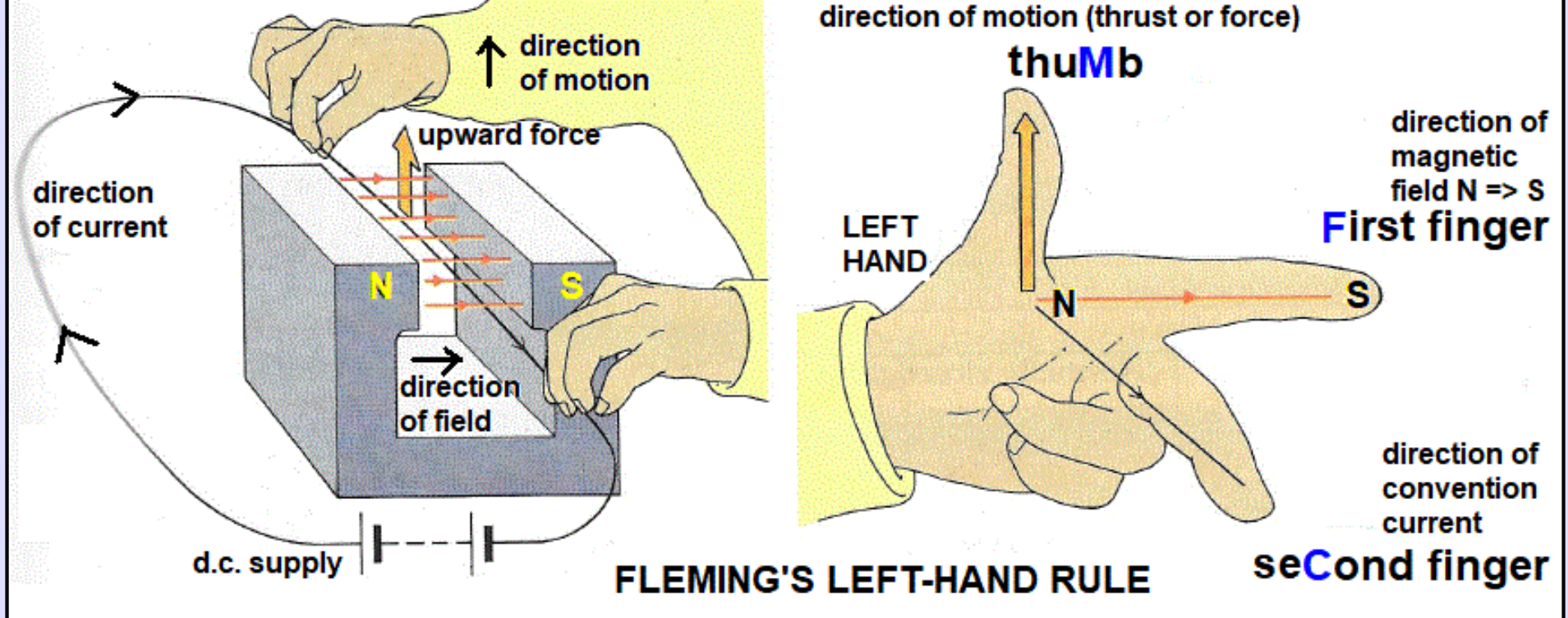
Use @@Fleming’s Left Hand Rule -- the force always acts a right angles to the magnetic field of the magnet + the direction of the current in the wire.@@
The magnitude of the force increases with…
- Increase in current flow (I)
- The strength of the magnetic field of the permanent magnet (B)
- The length of wire exposed the magnetic field -→ as this means a greater length/area of wire where the two magnetic fields interact. (L)
%%The net force created (F) = IxBxL%%
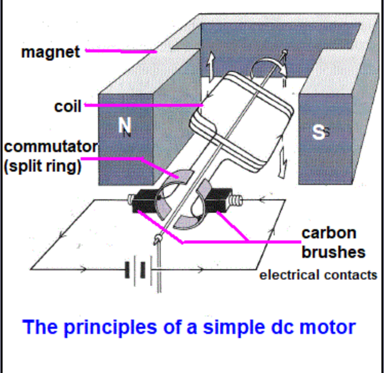
Simple D.C. Electric Motor
Instead of a single linear wire, place a D.C. current-carrying loop in the magnetic field of a permanent magnet (U shaped) or opposite poles from two permanent magnets.
Due to the motor effect, the left side of the loop will move downwards and the right side will move upwards, giving anti-clockwise rotation.
However, you will not get continuous rotation without some further modifications…
- An axle → about which the coil can rotate freely between the poles of the permanent magnet.
- A Split ring commutator → swaps around the contacts every half-turn (swapping the +/- polarity), which swaps the direction of the resulting force -- this keeps the rotation in the same direction.
- Brush contacts → a strip of graphite or copper which enables rotational movement to continue but still maintain a complete electrical circuit -- the brushes sweep over the surface of the contacts on the axle.
Theoretically, when the wire coil is vertical, the circuit is broken for a split second, BUT the momentum of the coil carries the rotation a bit further so that the circuit is complete again.
You can reverse the direction of rotation either by:
- Swapping the polarity of the D.C. supply to change the direction of current flow.
- Swapping the magnetic poles of the permanent magnet to change the direction of the magnetic field.
Sources of energy loss in a simple D.C motor
- When the motor starts running, the current decreases a little as the wire coils act as a resistance, causing the coil to heat up and heat energy is lost to the surrounding air.
- The machine also acts as a generator -- as the coil rotates in the magnetic field, it induces a current to flow in the opposite direction.
How to make a simple D.C motor more powerful…
- Increase the number of turns of wire in the coil
- Wind the coil on a soft-iron bar -→ to increase the magnetic flux through the coil
- Make the field magnet as strong as possible
- Increase the current through the wire
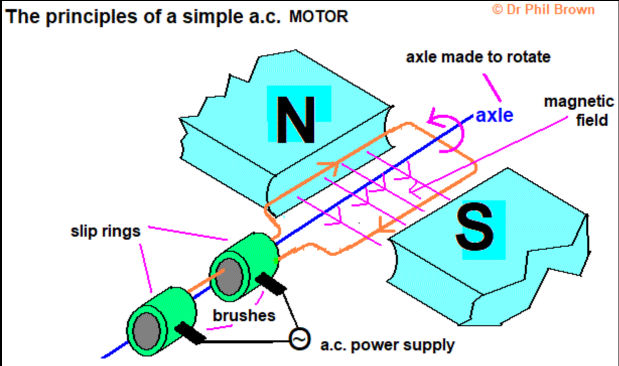
Simple A.C. electric Motor
The A.C. power supply is connected to the rotating coils of the armature by @@two slip-rings@@ and carbon brush contacts.
As the coil rotates, the direction of the current passing through the coil reverses direction.
When the coil has moved half a turn, the direction of the current has reversed.
This ensures the force, produced by the interaction of the two magnetic fields, always operates in the same net direction so the rotation of the coil is always in the same direction.
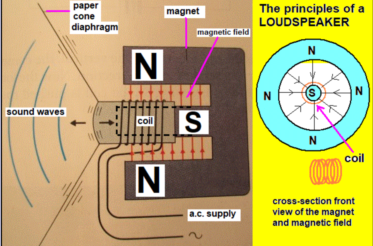
The Loudspeaker - an application of the Motor Effect
- An A.C. current is passed through a coil of insulated copper wire attached to the base of a cone.
- The coil is wrapped around one pole of a permanent magnet and is itself surrounded by the other magnetic pole.
- The permanent magnet produces a strong magnetic field at right angles to the coil.
- When the current passes through the coil, it produces a magnetic field around the coil of wire, which interacts with the magnetic field of the permanent magnet, causing a force.
- This force moves the cone.
- When the A.C. current reverses direction, the force acts in the opposite direction, so the cone moves in the opposite direction too.
- The cone vibrates (oscillates) which causes the surrounding air particles to vibrate, producing sound waves from the speaker that can be heard.
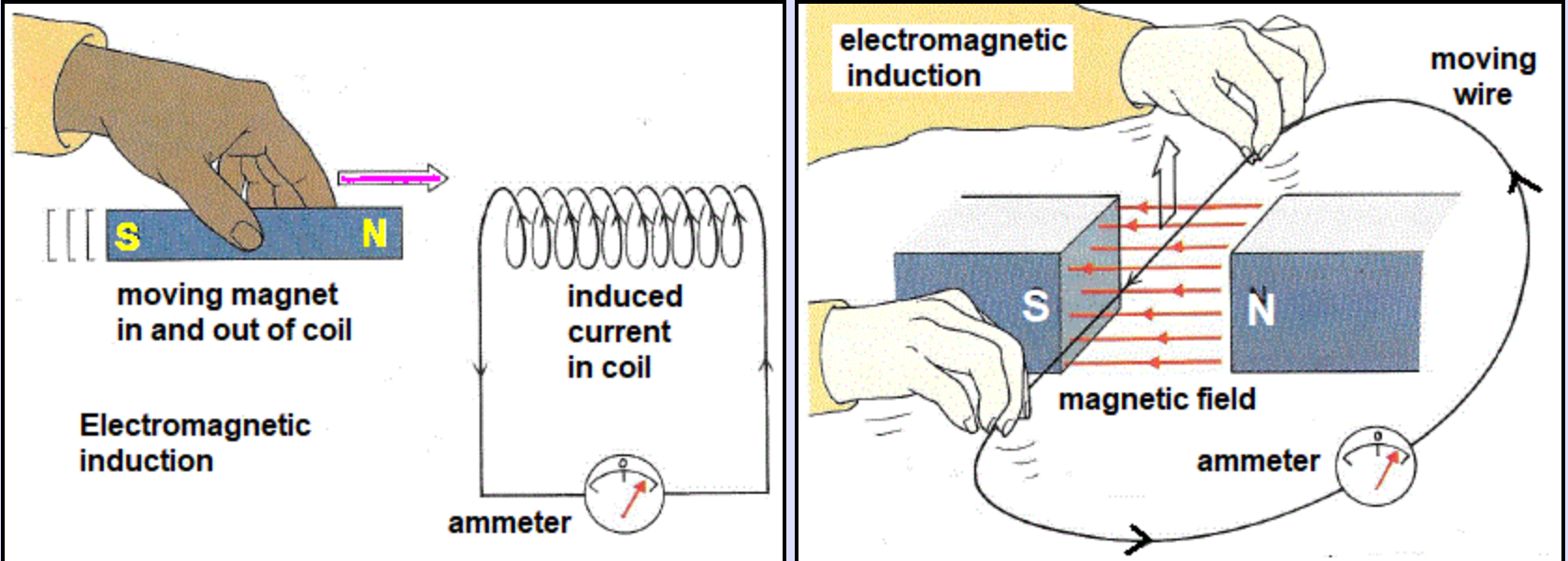
The Generator Effect - generating electricity
Electricity can be generated from the Generator Effect, which is an example of electromagnetic induction.
You can induce a p.d. in an electrical conductor by:
- A wire moving relative to a magnetic field → [a wire moving between the poles of a stationary permanent magnet]
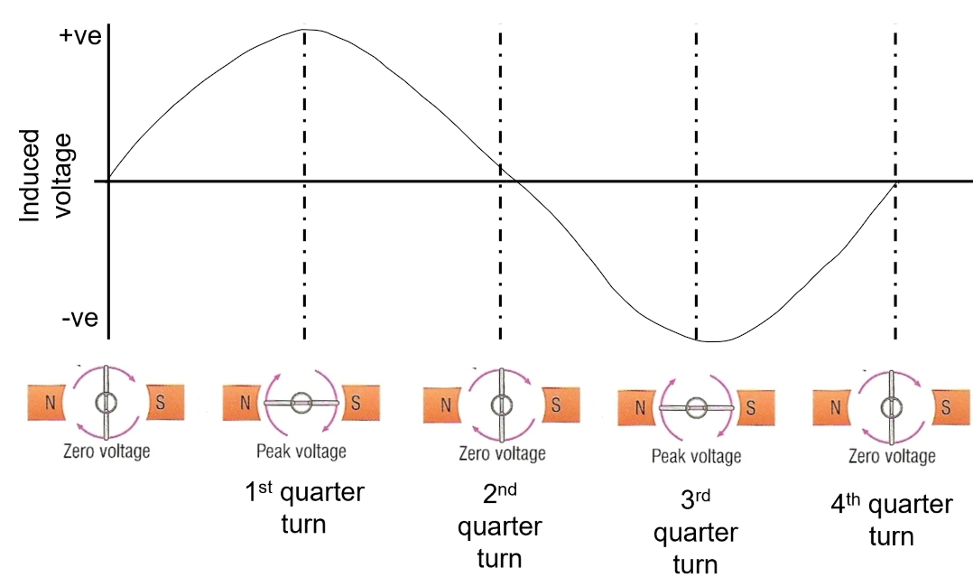
- A wire experiences a changing magnetic field → [a magnet rotated in a coil of wire]
Moving a magnet in and out of a coil of wire or moving a wire through a magnetic field. Both of these methods induce a current in the wire.
You can increase the induced p.d. (and therefore the current) by…
- Moving the wire/magnet faster
- Using a more powerful magnet
- Using a multi-coil of wire → the same magnetic field is interacting with a greater length of wire.
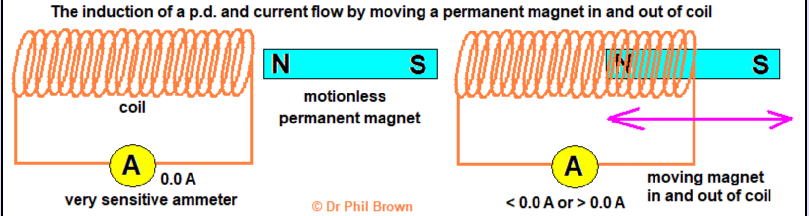
Demonstration 1) Circuit consisting of an insulated copper wire connected to a very sensitive ammeter.
If you bring the magnet near the coil, but stationary, the ammeter remains at 0.0 A.
BUT if you move the magnet in and out of the coil, a voltage and therefore a current is induced in the wire.
When the magnet 'goes in' you should get a 'blip' of an ammeter reading above 0.0 A in one direction and when you pull the magnet out, you get a 'blip' of an ammeter reading of less than 0.0 A.
It is the change in magnetic field the wire experiences that induces the voltage and the current flow.
Changing the direction of motion changes the direction of the voltage and induced current.
Also, swapping the poles of the magnet around causes the two ammeter readings to be reversed (the +ve becomes -ve).
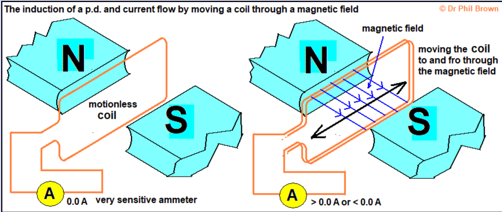
Demonstration 2) A moving coil and stationary magnet
You need a U shaped magnet or two permanent magnets. The coil of wire is connected to an ammeter.
While the coil is stationary, the ammeter reading stays at 0.0 A.
However, as you move the coil in and out of the magnetic field at 90’, a voltage and current is induced.
When you move the coil in one direction, the induced current flows one way (e.g. ammeter reads >0.0 A) and if you move the coil in the other direction, the induced p.d. and current are also reversed (e.g. ammeter reads <0.0 A).
Here the magnetic field has a constant direction but the motion is continually reversed, once again producing an alternating current as the induced p.d. is also reversed.
BUT>>> An induced current opposes the change that caused the induction
A change in magnetic field induces a current in a conductor. BUT, when a current flows through a wire, a magnetic field is created around the wire. So, we are now dealing with two magnetic fields.
The magnetic field produced by the induced current in the wire always acts against the change that made it.
You are building up an electrical energy store from another energy store!
You can't get energy for nothing!
The National Grid System Electricity Supply
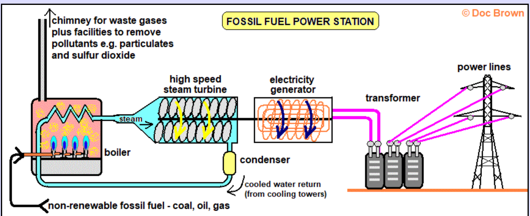
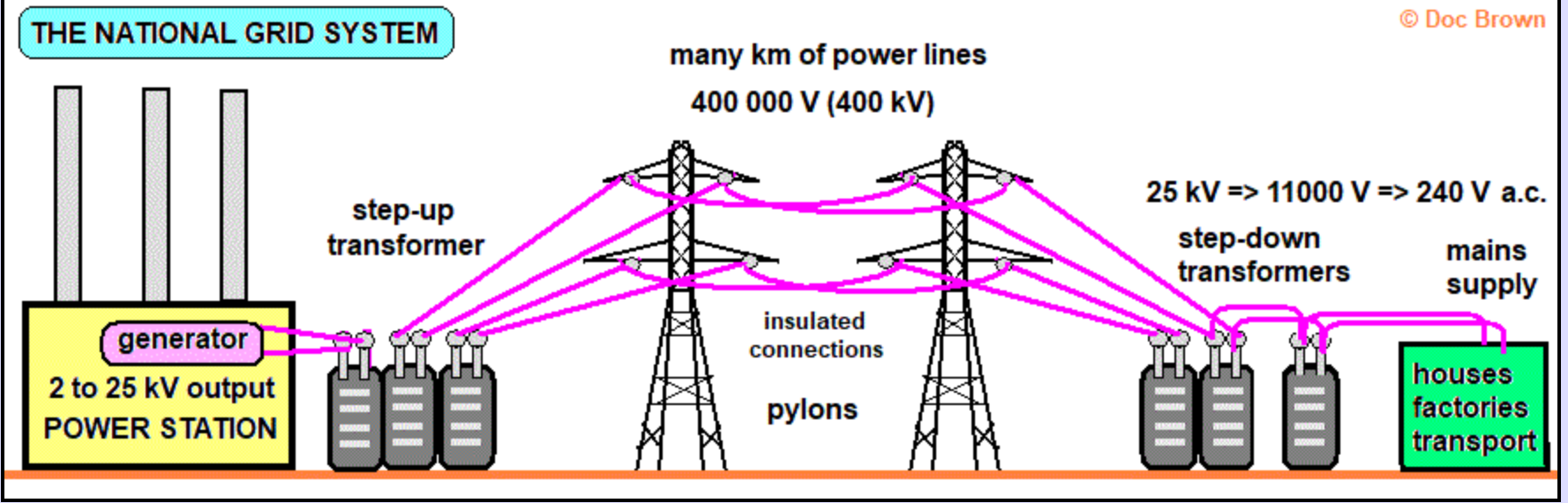
Electricity is distributed from power stations to consumers along the National Grid.
In the UK, the generator output at the power station is 25,000 V.
- A step up transformer: increases the voltage - for powerline transmission (to 400,000 V).
- A step-down transformer: decreases the voltage - to more suitable and safer for home and industry (typically 230 V)
For transmission of electricity, you want a high voltage and low current.
- Low current because: the greater the current, the greater the heat generated, so more heat waste energy → less efficient. Since P = E/t = I2R, the power loss is a function of I2 for a fixed resistance - the National Grid cables.
- However, since power = current x voltage, to deliver a particular power rating, you must still increase one of the two variables and decrease the other. So voltage must therefore be high.
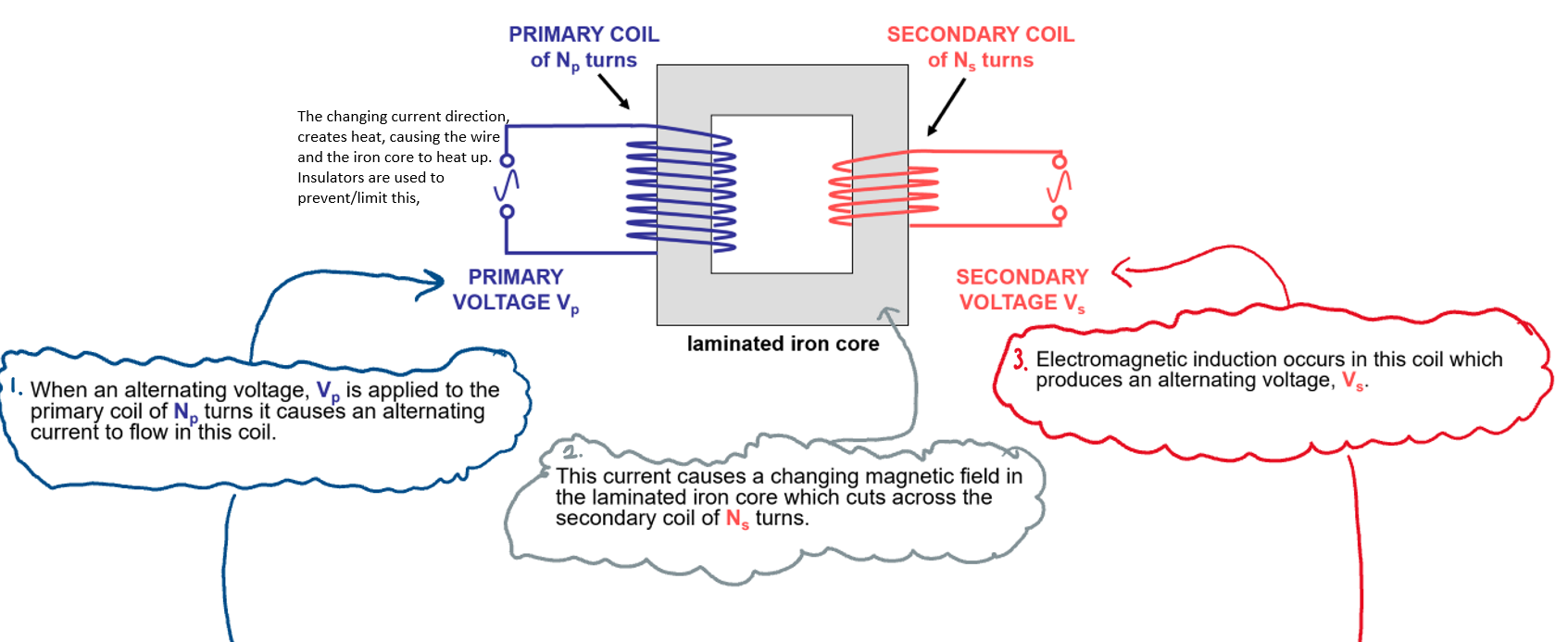
Transformers: devices that can change the voltage of an A.C..
Consists of two coils of insulated wire: a primary coil and a secondary coil**, independently** wound around an iron core.
Iron is used because it is easily temporarily magnetised.
- When an A.C. current flows through the primary coil, the iron core magnetises and demagnetises quickly (due to the alternating current).
- Therefore a changing magnetic field in the iron core is created.
- This changing magnetic field is constantly cutting through the secondary coil, inducing a voltage and causing an induced current to flow in the secondary coil.
Transformers do not allow DC input to flow through. This is because a change in current cannot be generated by DC; meaning that there is no changing magnetic field to induce a voltage across the secondary component.
\n