Introduction to Microcontrollers and Architecture
SECTION I: Theory
1.1 Introduction to Microcontrollers
To design and construct a 0028ebMARV, understanding a microcontroller's basic structure and operation is essential.
Embedded System: Unlike general-purpose computers, a microprocessor-based system has a dedicated task.
Embedded Design: The process by which an embedded system is created.
Examples include toys, watches, microwave oven controllers, and timing systems for track events.
1.1.1 What is a Microprocessor or a Microcontroller?
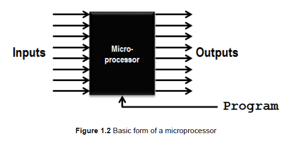
A microprocessor is a digital device that accepts data, processes it, and controls connected devices.
Inputs and outputs can be discrete (1 or 0) or parallel (binary numbers).
Microprocessor (µP): Only a central processing unit.
Microcontroller (µC): A composite device with a microprocessor, onboard memory, and onboard peripherals (Oscillators, timers, counters, input/output interfaces, ADCs, comparators, and PWMs) in a single integrated circuit.
EMK310 focuses on microcontrollers, specifically PIC (Programmable Interface Controller) devices.
1.1.2 Where do Microprocessors Come From, and Where Do We Use Them?
4-bit microcontrollers: Early 1970s.
8-bit microcontrollers: Mid-1970s.
16-bit microcontrollers: Early 1980s.
32-bit microcontrollers: State-of-the-art until the mid-1990s.
64-bit processors: Commonly used today.
128-bit processors: Not commercially available yet, but some operating systems and hardware implementations exist.
(The number of bits in a microcontroller or processor refers to the width of the data bus, which determines how much data the processor can handle simultaneously. For instance, an 8-bit microcontroller can process 8 bits of data in one operation, while a 64-bit processor can handle 64 bits at once. Higher bit processors generally offer greater speed, efficiency, and the ability to address more memory.)Microprocessors and microcontrollers are used in almost everything electrical, including household appliances, cars, airplanes, toys, mobile phones, and fitness watches.
1.1.3 "Our" µCs
EMK310 uses the 8-bit PIC18F45K22 to explore microcontroller architecture, programming, and interfacing.
97% of the module focuses on microprocessor system design and implementation using the PIC18F45K22.
The PIC18F45K22 will be programmed in Assembly language to ensure understanding of the hardware foundation.
1.1.4 What µCs Can and Cannot Do
Microcontrollers cannot "think"; they require precise instructions.
Erratic behavior is usually due to incorrect programming or external factors like power supply noise.
1.1.5 Representing Bits in µCs
A microcontroller's program is called firmware, residing in the device's program memory.
Firmware consists of instructions coded as binary numbers.
Instructions are fetched from memory, decoded in the CPU's control unit, and then generate control signals.
Data is represented by 0s and 1s (bits) using voltage levels.
Logic 1 = 5V (ideal).
Logic 0 = 0V (ideal).
TTL (transistor-transistor logic) voltage levels:
Inputs:
Low: 0 to 0.8V
High: 2.0 to 5.0V
Outputs:
Low: 0 to 1.5V
High: 2.7 to 5.0V
CMOS (complementary metal oxide semiconductors) voltage levels:
Inputs:
Low: 0 to 1.5V
High: 3.5 to 5.0V
Outputs:
Low: 0 to 0.05V
High: 4.95 to 5.0V
High-Impedance State: Disconnects a pin from an output circuit, preventing interference when multiple circuits share the same output pin.
Pull-up or pull-down resistors are used to force a floating pin (neither connected to HIGH nor LOW) to a logic value.
1.1.6 Programming µCs
Instructions can be represented by binary code (e.g., 0000 1000 0000 0011).
Hexadecimal numbers (e.g., 0803h) are a more condensed representation.
Assembly language uses mnemonics (e.g.,
movf STATUS,W).movf STATUS,W: Moves the contents of the STATUS file register into the W register.A register is a collection of binary digits (bits).
Assembly language allows programming at a low level (bit (0 or 1), byte (8 bits), and word (16 bits or 32 bits etc.) level).
1.2 Architecture
1.2.1 What is µC "Architecture"?
µC architecture refers to the device's parts, interconnections, and operating principles.
Includes hardware setup, instruction set type, memory structure, instruction execution (pipelined or not), and word size.
1.2.2 Hardware Architecture
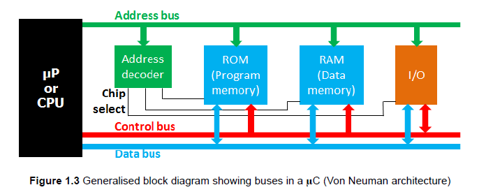
A µC typically consists of a µP or CPU, memory, and input/output devices.
Digital signals move along three buses: data bus (carries the actual data), address bus (specifies the memory location or the address of the deRvice that the CPU wants to access), and control bus (transmits control signals).
CPU Components:
Arithmetic and Logic Unit (ALU): Performs calculations and binary operations.
Registers:
Program counter: Contains the address of the next instruction (it ensures that the instructions are executed in the correct sequence).
Working register (W register or accumulator): Data is loaded for operation and results are returned (data is loaded into the W register, the CPU performs an operation on it, and then the result is stored back into either the W register or another memory location).
Status register: Contains flags indicating operation status (e.g., carry flag, zero flag).
Control unit: Manages data movement among CPU components.
Other µC Devices: Oscillators, timers, counters, input/output interfaces, ADCs, comparators, and PWMs.
1.2.2.1 Architecture of the PIC18F45K22
Key components for constructing a MARV:
Oscillator circuits: Provide the clock signal.
ALU and W register: Used for calculations and bit operations.
Data memory: Stores variables and sensor data.
ADC: Digitizes sensor signals (digitizing sensor signals means converting analog signals from sensors into a digital format that the microcontroller can process).
Timers: Implement delays and timing requirements.
EUSART: Creates a serial communication link with a PC or mobile device.
Program memory: Holds the firmware program.
Stack: Stores return addresses for interrupts and subroutines.
Program counter: Indicates the location of the next instruction.
CCP module: Generates control signals for motors.
Programming and debugging unit: Allows programming and debugging from a PC.
I/O ports: Connect LEDs, sensors, and output devices.
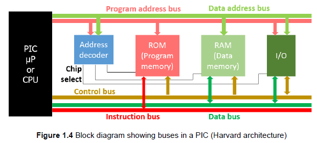
Buses: Instruction bus, data bus (8 bits wide), and data memory address bus (12 bits wide).
1.2.2.2 Buses
Buses facilitate communication among µC components.
SFR - Special Function Registers are registers in a microcontroller that have specific, predefined functions related to controlling and monitoring the microcontroller's hardware peripherals and system-level operations.
GPR - General Purpose Registers are registers in a microcontroller that are available for the programmer to use for any purpose, such as storing variables, intermediate calculations, or data.
Example Instruction:
MOVFF ADRESH, Sensor1(moves the content of ADRESH to Sensor1).ADRESH: Special function register (SFR) in data memory (stores the most significant bits of the result from the analog-to-digital conversion).
Sensor1: Register in general-purpose register (GPR) data memory.
Bus Operations:
Address bus carries the instruction's program memory address.
Instruction bus carries the instruction's binary code.
Address bus carries data memory addresses for ADRESH.
Data bus carries the instruction and content of ADRESH to the CPU.
The control bus regulates traffic on the buses.
Chip Select (CS) Lines: Control which device is addressed on a bus; sometimes called chip enable (acts as a switch that activates a specific device, allowing it to communicate on the bus while keeping other devices inactive).
Bus Definition: A collection of wires for communication, carrying data, addresses, and control signals.
Data Bus:
Width determines the number of input lines.
µCs are classified by data word size (e.g., an 8-bit µC has an 8-bit data bus).
LSb is bit 0, and MSb is bit 7 in PICs.
Tristate Outputs:
Output interfaces use tristate outputs (high-impedance output) to prevent inactive devices from creating low-impedance current paths.
States: 1 (high signal), 0 (low signal), and Z (high impedance).
Address Bus:
Each memory location or register has a unique address.
Only the device with the address on the address bus is enabled for communication.
Address decoders activate devices via chip select inputs.
Control Bus:
Carries control signals (read/write) and clock signals.
READ/WRITE : High (1) indicates a read, low (0) indicates a write.
Clock signals synchronize µC functions (operate in a coordinated manner).
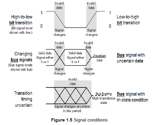
1.2.2.3 Timing Diagram Convention
Timing diagrams visually represent signals on lines, buses, and inside registers.
Oblique lines in timing diagrams indicate the brief but measurable time it takes for signals to change states.
Bus signals are represented with a bar since they contain multiple lines.
Bit signals are represented as high or low signals.
1.2.3 Type of Instruction Set
µC architecture includes the instruction set implementation (RISC or CISC).
RISC (Reduced Instruction Set Computer): Uses simple, single-function instructions.
CISC (Complex Instruction Set Computer): Uses instructions with a lot of functionality in a single instruction.
RISC instruction sets have fewer instructions than CISC.
PIC18s are RISC machines with 75 instructions.
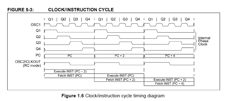
1.2.3.1 Instruction Cycle Timing
The fetch-execute cycle involves fetching an instruction, then decoding and executing it.
The instruction cycle of the PIC18F45K22 takes 4 clock cycles.
If the clock runs at 4 MHz, the instruction cycle frequency will be 1 MHz.
Instruction Pipeline: Overlaps instruction execution to increase throughput.
The next instruction is fetched while the previous one is executed.
PIC18 throughputs one instruction per four clock cycles even though the entire fetch-execute cycle takes up eight cycles (i.e., two instruction cycles).
SECTION II: Application
1.5 "Hello MARV"
Time to introduce the integrated development environment (IDE) and Assembly language programming.
Knowledge gained must be translated into the ability to provide a µC system solution to complex real-world problems.
Experimenting with firmware and hardware is crucial for practical understanding.
1.5.1 Where to Start?
Flashing an LED is equivalent to printing "Hello world."
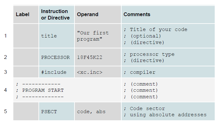
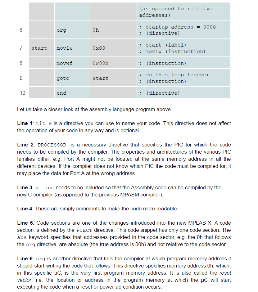
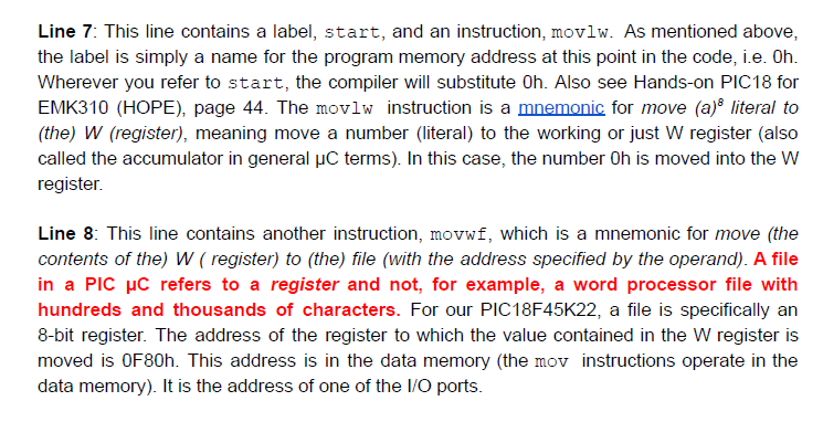
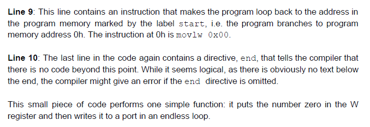
1.5.2 Our First Assembly Language Program
When writing code for your PIC, you need to understand the difference between instructions and directives.
Instructions are commands that the µC can interpret, while directives are commands that the compiler, which must translate the assembly language instructions to machine code, needs to compile the code correctly.