Avionics-FINALS Reviewer
PPT 7: Aircraft Instruments Part 1
Introduction:
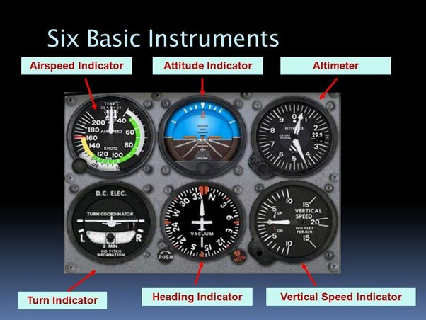
- All certificated aircraft are equipped with instruments, vital for safe operation.
- Instruments have evolved over time, with modern single-engine airplanes having more sophisticated instruments than earlier airliners.
Purpose of Aircraft Instruments:
- Instruments provide essential information for safe and efficient flight, especially when visual references are unavailable.
- They offer crucial data within the cockpit, ensuring the pilot can make informed decisions even in adverse conditions.
Instrument Categories:
- According to Application:
1. Powerplant Instruments: Provide data related to aircraft powerplants.
2. Flight and Navigation Instruments: Supply altitude, speed, and navigation-related information.
3. Systems Instruments: Offer data regarding aircraft systems like electrical, hydraulic, and pressurization systems.
- According to Means of Operation:
1. Pressure Instruments: Measure air, fuel, oil, etc., pressures.
2. Mechanical Instruments: Utilize mechanical systems for obtaining and transmitting information.
3. Gyro Instruments: Employ gyroscope principles, primarily used for IFR flight.
4. Electrical and Electronic Instruments: Witnessed significant advancements due to digital technology.
Instrument Placement and Installation:
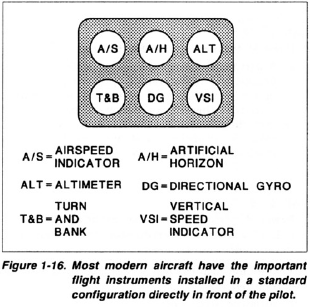
- Key instruments are typically placed directly in front of the pilot, facilitating easy scanning and transition between different aircraft types.
- Instruments come in standard sizes, with round instruments following standard sizes ranging from 1" to 4".
Installation Methods:
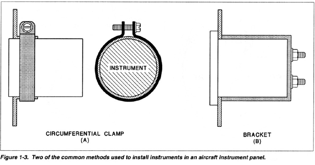
- Instruments are installed using screws, circumferential clamps, or brackets for secure placement.
Instrument Markings:
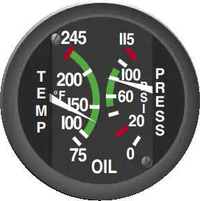
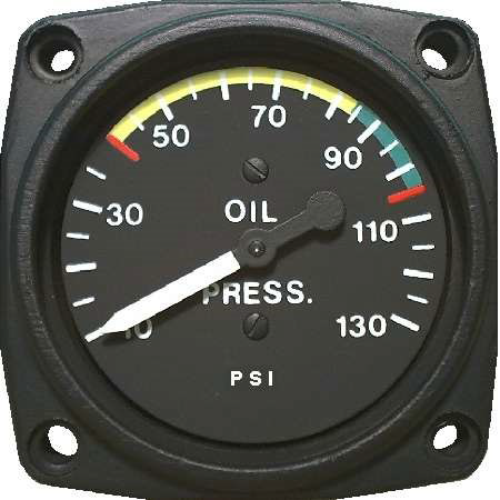
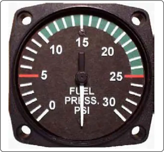
- Instruments often feature colored markings indicating safe operating values, with red indicating maximum or minimum operating limitations and yellow denoting caution ranges.
1. Red Radial Line
- Indicates a maximum or minimum operating limitation.
- Example: On an oil pressure gauge.
2. Red Arc
- Indicates a prohibited range of operation.
- Example: Commonly seen on a tachometer due to vibration problems at certain RPMs.
3. Yellow Arc
- Indicates a caution range.
4. Green Arc
- Represents the normal operating range.
5. Blue Arc or Line
- Meaning specified by the manufacturer.
- Example: Blue arc on a manifold pressure gauge for engine operation with a lean mixture.
Instrument Lighting:
- Correct installation of instrument lighting is crucial to avoid shorts or interference.
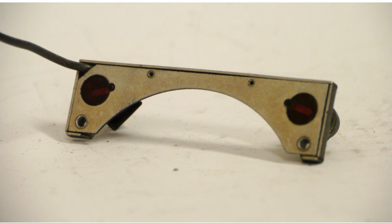
1. Eyebrow Lights
- Small semi-circular fixtures resembling eyebrows, fitting over the top of round instruments.
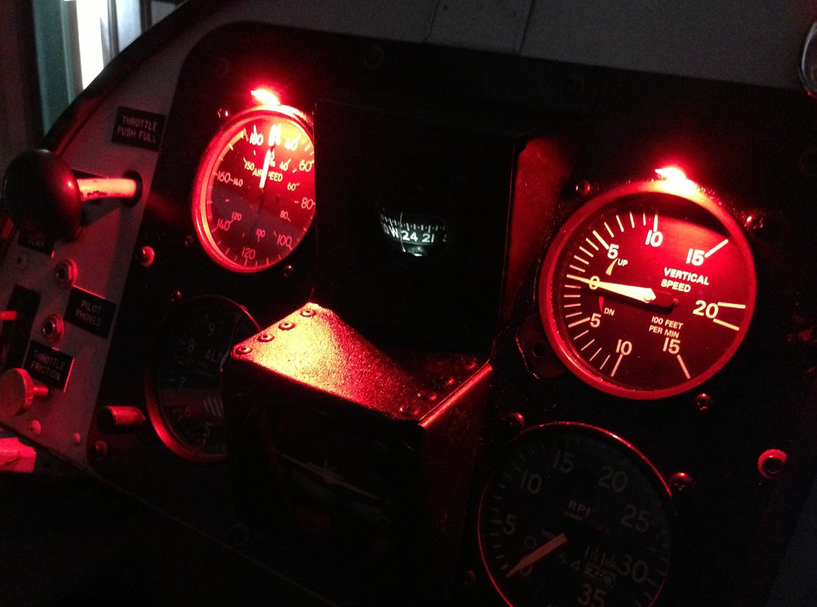
2. Post Lights
- Small round lights installed into holes in the instrument panel.
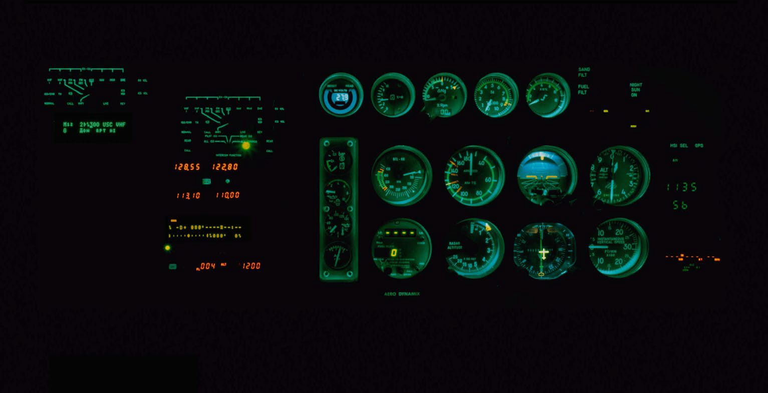
3. Internal Lights
- Lights positioned inside the instrument case.
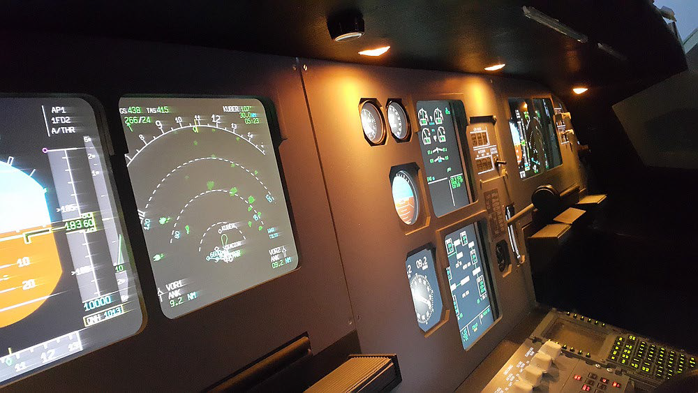
4. Flood Lights
- Lights aimed at the instrument panel, shielded to prevent glare in the pilot's eyes.
- Often installed in addition to other types as a backup lighting system.
FAR 91.9: Instrument and Equipment Requirements
Visual Flight Rules (VFR) Day:
- Required Instruments:
1. Airspeed indicator
2. Altimeter
3. Magnetic direction indicator
4. Tachometer for each engine
5. Oil pressure gauge for each engine
6. Temperature gauge for each liquid-cooled engine
7. Oil temperature gauge for each air-cooled engine
8. Manifold pressure gauge for each altitude engine
9. Fuel quantity gauge for each tank
10. Landing gear position indicator (if retractable)
VFR Night:
- Additional Requirements:
1. Position lights
2. Anti-collision lights (red or white)
3. Adequate electrical energy source for all electrical equipment
4. One electric landing light (if operating for hire)
5. Spare fuses
Instrument Flight Rules (IFR):
- Required Equipment:
1. Equipment for VFR day and night as appropriate
2. Two-way radio communications equipment
3. Radio navigation equipment
4. Gyroscopic rate-of-turn indicator
5. Slip-skid indicator
6. Sensitive altimeter
7. Clock displaying hours, minutes, and seconds
8. Generator or alternator
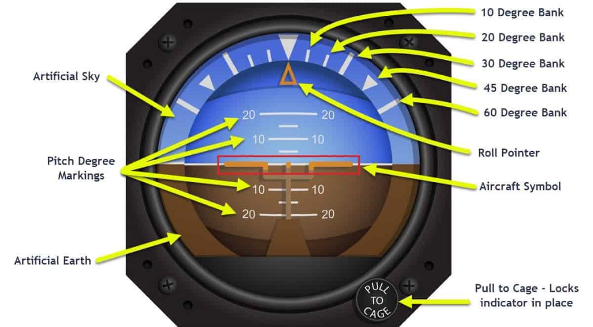
9. Gyroscopic bank and pitch indicator (artificial horizon)
10. Gyroscopic direction indicator (Heading indicator)
11. DME system for flight at and above 24,000 ft. MSL
Pressure Measuring Sensors:
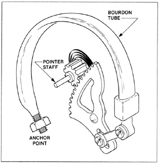
- Bourdon Tube:
- Curved, hollow tube made of springy metal.
- Measures relatively high pressure, typically 20 PSI or more.
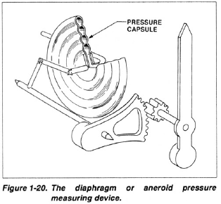
- Diaphragm:
- Thin, lens-shaped hollow metal container.
- Measures relatively low pressures, such as in altimeters or airspeed indicators.
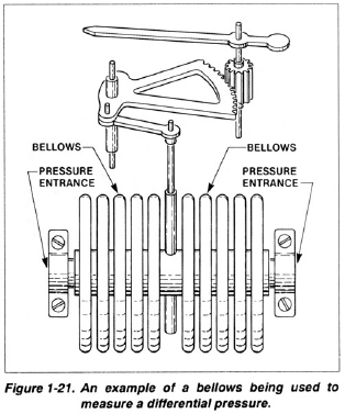
- Bellows:
- Longer than diaphragm, with accordion folds.
- Measures relatively low pressures, often used for differential pressure.
Units of Measure for Pressure:
- Common units in aviation include:
1. Pounds per Square Inch (PSI)
2. Inches of Mercury (in. Hg)
3. Millibars (mbar)
4. Kilopascals (kPa)
Types of Pressure Measurement:
- Absolute Pressure: Measured compared to a complete vacuum.
- Gauge Pressure: Measured compared to atmospheric pressure.
- Differential Pressure: Measured compared to two different pressure sources.
Pitot-Static Systems:
- Definition: System comprising ports (pitot and static ports) and tubing supplying pitot and static pressure for instruments.
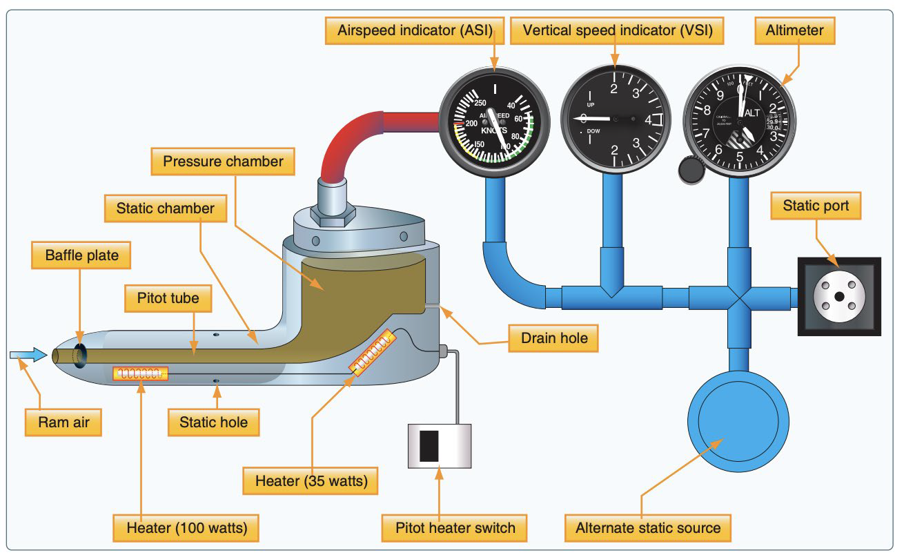
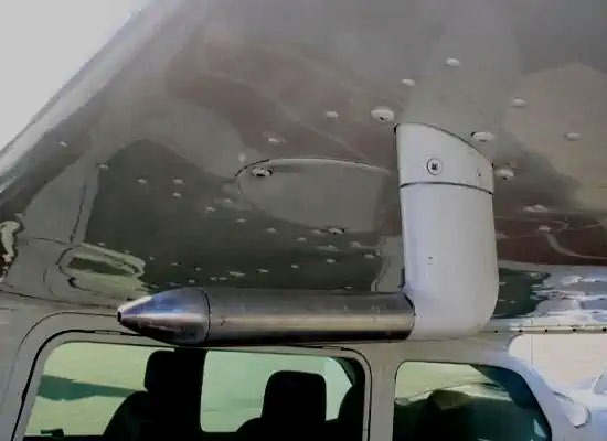
- Pitot Tube:
- Open tube facing forward into relative wind, measuring ram pressure.
- Typically installed below wing or on nose section of aircraft.
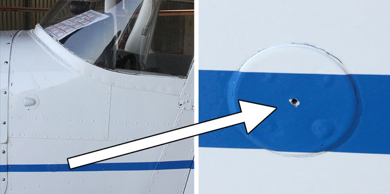
- Static Port:
- Openings at right angles to relative wind, measuring static pressure.
- Often located in pairs along fuselage sides or integrated with pitot tube.
Altimeter:
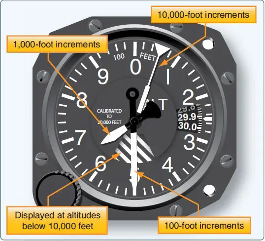
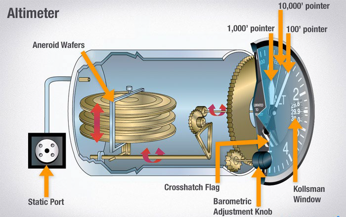
- Function: Measures atmospheric pressure as altitude above mean sea level (MSL).
- Altitude Measurement:
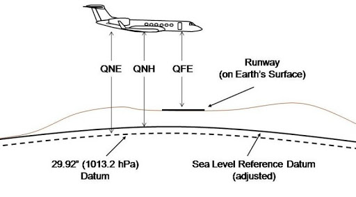
- Referenced to average level of major oceans.
- Uses standard atmosphere table for pressure and altitude changes.
- Pressure Measurements:
- QNH (Query Nautical Height): Pressure measured from sea level.
- QNE (Query Nautical Equivalent): Pressure measured from standard datum.
- QFE (Query Field Elevation): Pressure measured from Earth's surface.
- Mechanism: Utilizes three diaphragms in series, sensitive to pressure changes.
Encoding Altimeter:
- System transmitting aircraft altitude data to ground radar system via transponder (Mode C).
Airspeed Indicator:
- Purpose: Indicates airspeed, not groundspeed.
- Operation: Measures differential pressure between pitot and static sources.
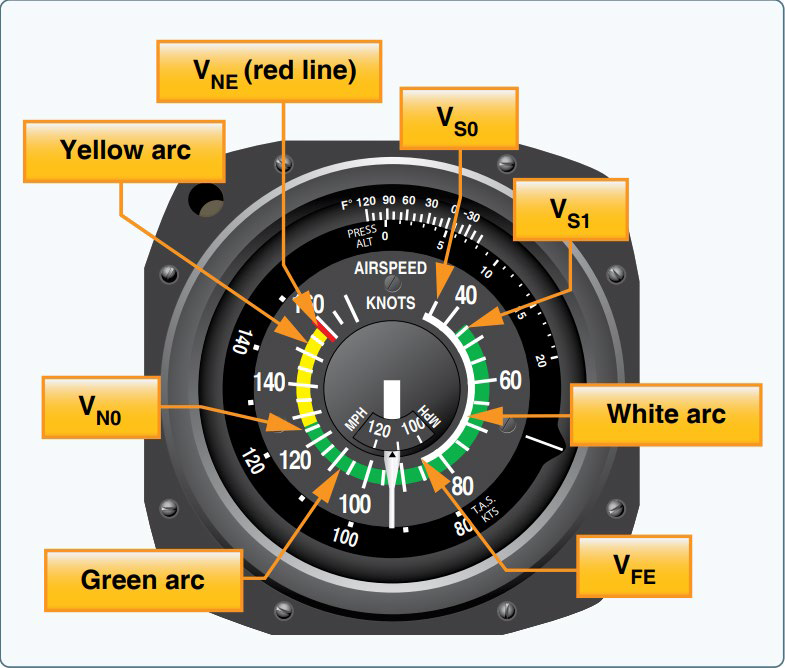
- Types of Airspeed:
1. Indicated Airspeed
2. Calibrated Airspeed
3. True Airspeed
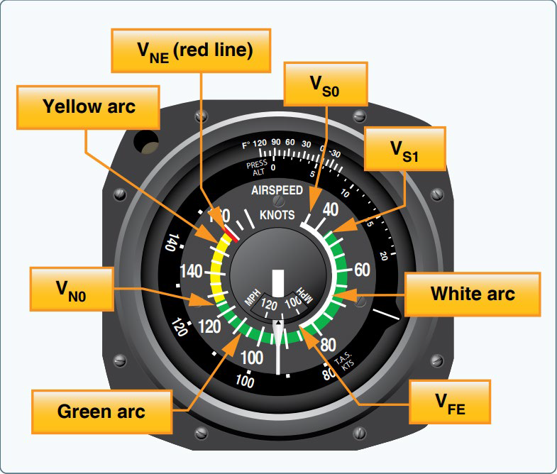
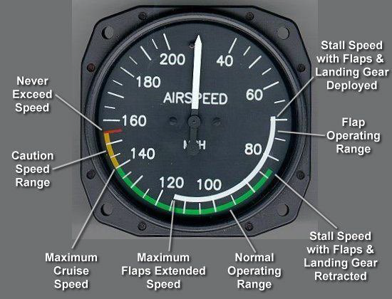
- Markings: Includes various speeds such as stall speed, maximum structural cruise, and never exceed speed.
Types of Airspeed:
1. Indicated Airspeed (IAS)
- Reading on the airspeed indicator.
2. Calibrated Airspeed (CAS)
- Indicated airspeed corrected for position and instrument errors.
3. True Airspeed (TAS)
- Calibrated airspeed corrected for altitude and temperature effects.
Airspeed Indicator Operation:
- Utilizes a diaphragm to measure differential pressure between pitot pressure and static pressure.
- Pitot pressure connected to the inside of the diaphragm; static pressure to the outside.
Airspeed Indicator Markings:
1. VS0
- Stall speed with gear and flaps down. Shown by bottom of white arc.
2. VS1
- Stall speed with gear and flaps up. Bottom of green arc.
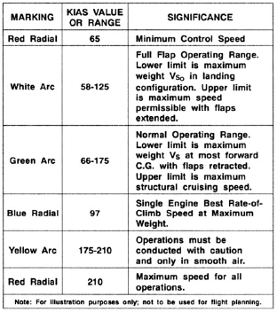
3. VMC
- Minimum control speed with critical engine failed. Red radial line in lower range of indicated airspeeds.
4. VFE
- Maximum speed with flaps down. Top of white arc.
5. VNO
- Maximum structural cruise. Top of green arc or bottom of yellow arc.
6. VNE
- Never exceed speed. Red radial line at highest permitted airspeed, or top of yellow arc.
7. VYSE
- Best single-engine rate of climb speed.
Vertical Speed Indicator (VSI):
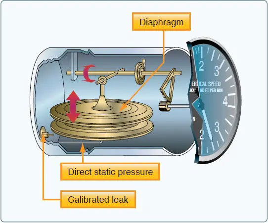
- Function: Measures rate of change of static pressure, indicating climb or descent rate.
- Operation: Static pressure connected to diaphragm, with pressure differential indicating climb/descent rate.
- Units: Measured in feet per minute (FPM).
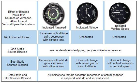
Abnormal Conditions of the Pitot-Static System
PPT 8: Aircraft Instruments Part 2
Gyro Instruments:
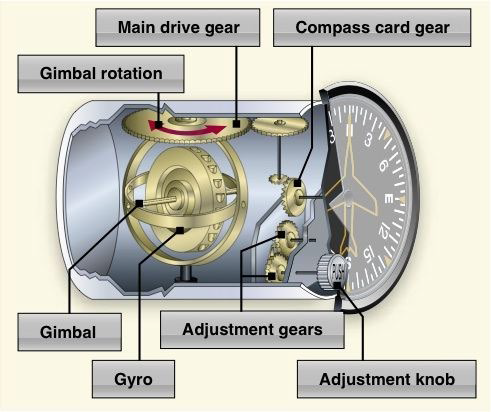
- Function: Utilize spinning gyroscope principles to provide information on aircraft's pitch, roll, heading, and rate of turn.
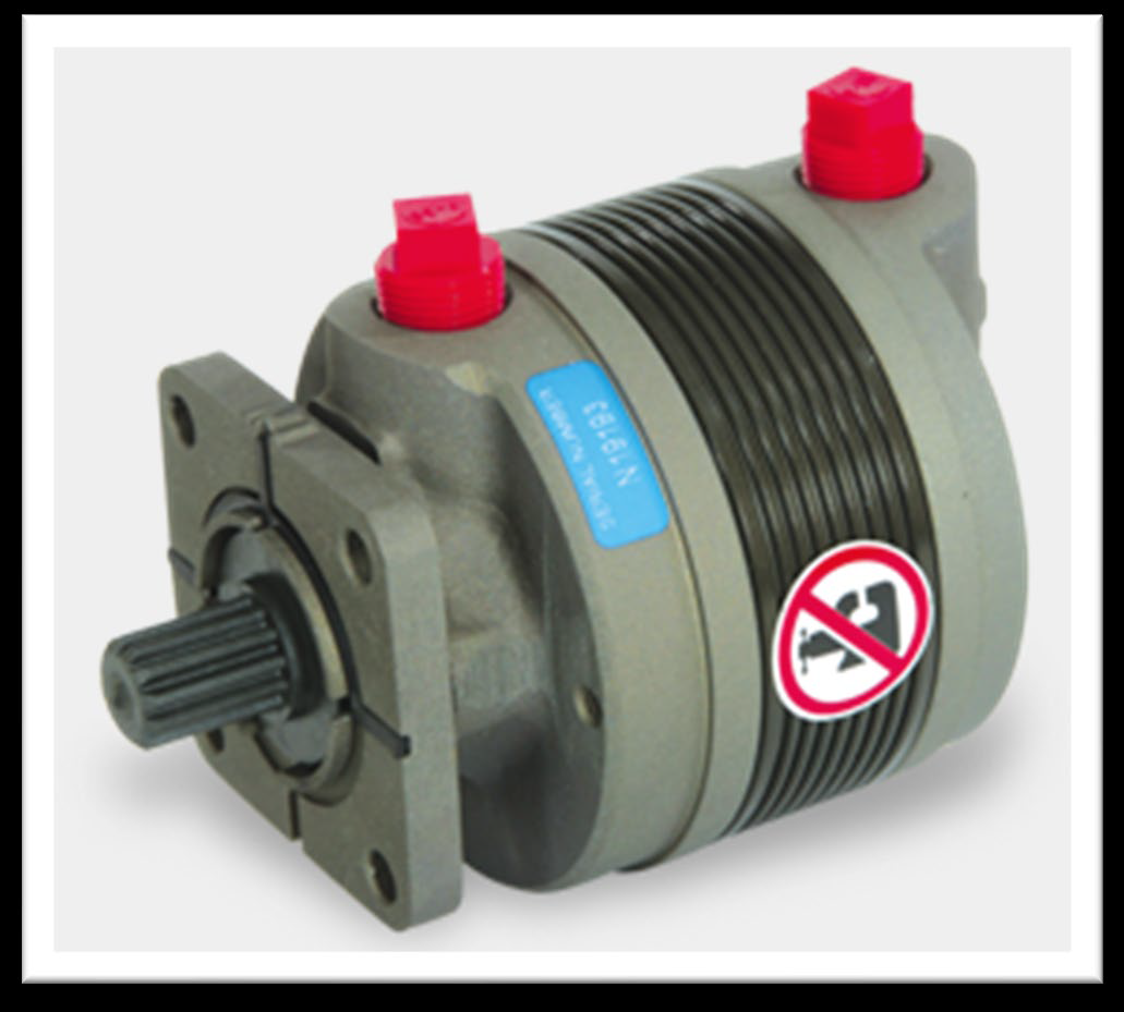
- Engine-Driven Vacuum Pump: Primary component responsible for generating vacuum.
- Relief Valve: Ensures system pressure does not exceed safe limits.
- Air Filter: Filters air to prevent debris from entering the system.
- Gauge: Mounted on the instrument panel, indicates system pressure.
- Tubing: Connects components to complete the vacuum system.
- Principles of Gyroscopes:
1. Rigidity in Space
- The gyro rotor endeavors to maintain its position in space despite tilts or rotations of its mounting base.
- This principle underlies the stability of gyroscopic instruments, allowing them to provide accurate reference points.
2. Gyroscopic Precession
- When an outside force acts upon a gyro, it responds by tilting or rotating as if the force were applied 90 degrees ahead in the direction of rotor rotation.
- Gyroscopic precession affects the behavior of gyro instruments, influencing their responsiveness to external forces.
- Types:
- Directional Gyro (Primary heading reference for IFR flight)
- Artificial Horizon (Most important for IFR flying)
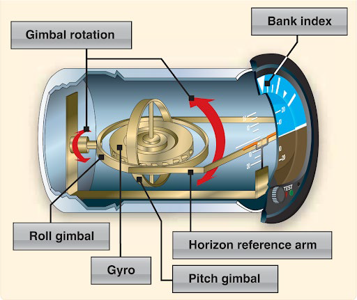
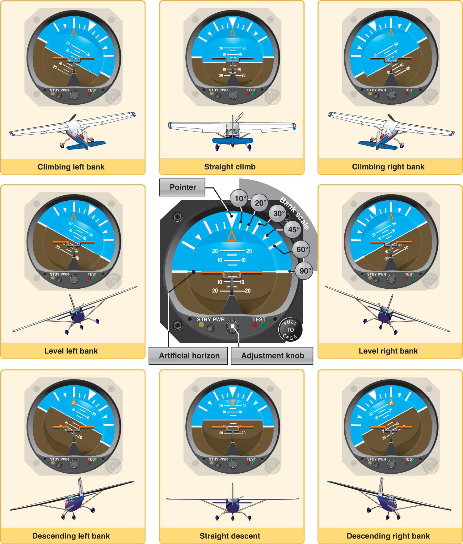
- Turn and Bank Indicator (Measures rate of turn and slip or skid)
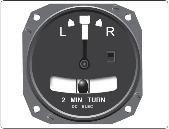
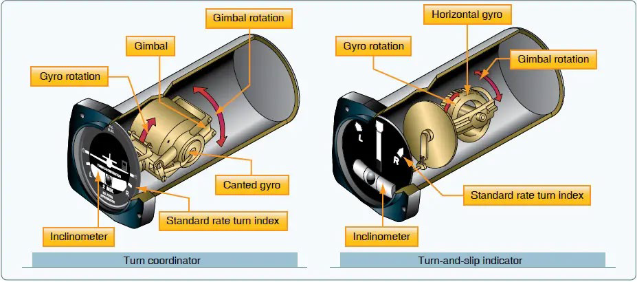
- Turn Coordinator (Modified version of turn and bank)
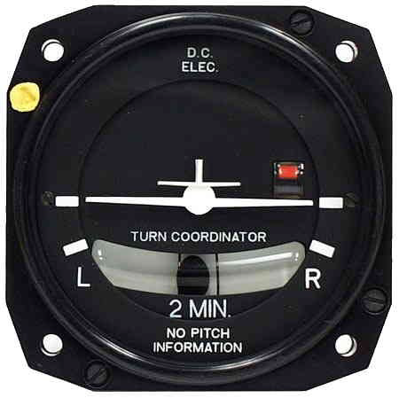
- Power Sources: Electric or air-driven (air pump or bleed air from turbine engines).
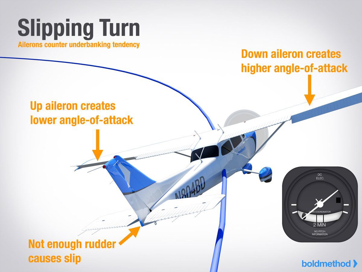
Slip:
- Aerodynamic condition of uncoordinated flight.
- Occurs when an airplane moves towards the inside of a turn or moves somewhat sideways relative to the oncoming airflow.
- Can result from insufficient rudder input in a turn or excess bank angle.
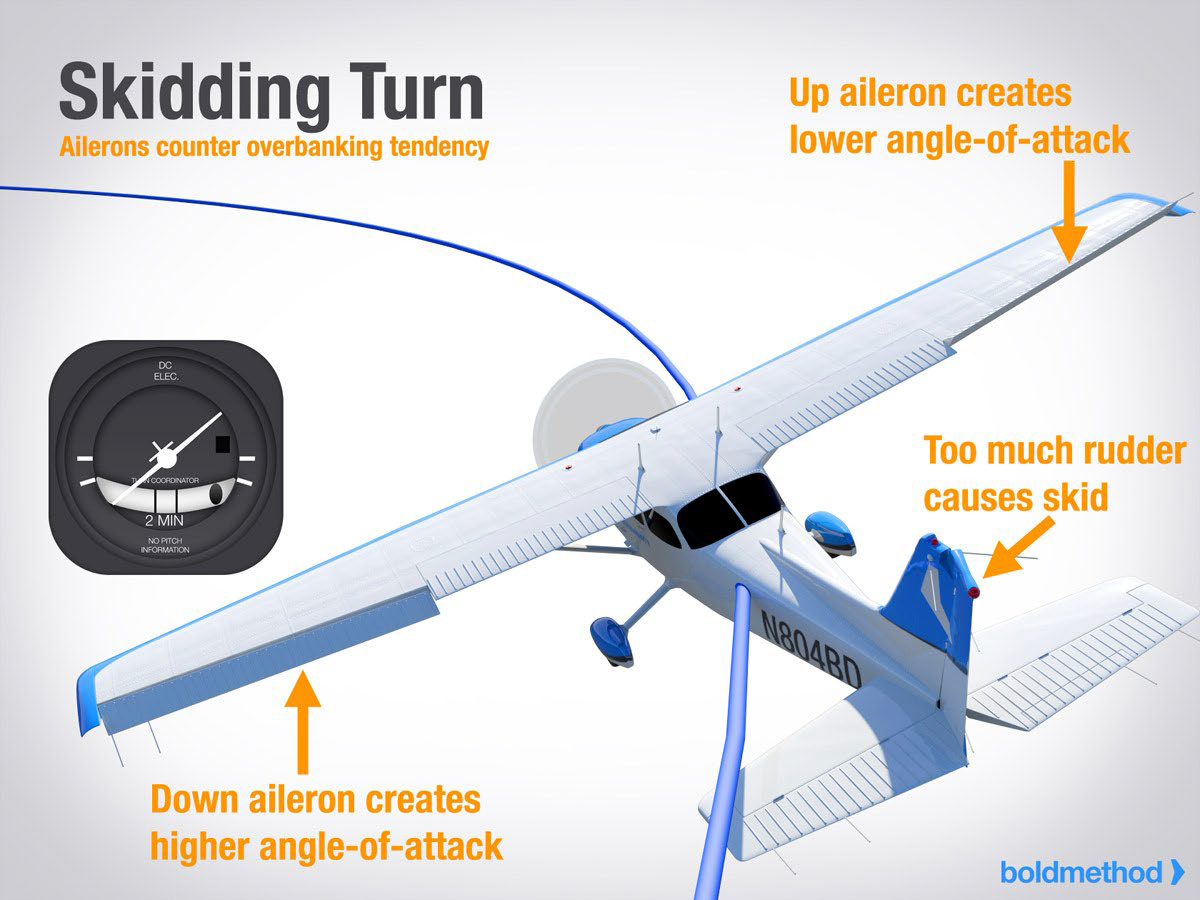
Skid:
- Aerodynamic condition during a turn.
- Occurs when the tail of an airplane moves away from the center of the turn or follows a path outside that of the nose.
- Typically caused by excessive rudder input or insufficient bank angle in a turn.
Compass Systems:
- Magnetic Compass:
- Independent instrument, unaffected by electrical or tubing connections.
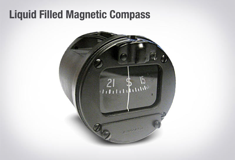
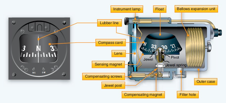 Components of a Magnetic Compass
1. Compass Card or Float
- Mounted on jeweled bearings.
- Contains numbers and direction markings for reading the aircraft's magnetic heading.
2. Case
- Filled with light oil (usually refined kerosene) to dampen float motion and lubricate bearings.
3. Diaphragm or Bellows
- Accommodates thermal expansion and contraction, ensuring consistent performance.
4. Compensator
- Consists of two small moveable magnets.
- Used to adjust the compass for deviation error caused by magnetic influences within the aircraft.
5. Lubber Line
- Marker against which readings are taken, facilitating accurate interpretation of magnetic heading.
Compass Errors
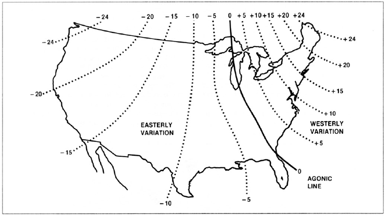
1. Variation Error
- Arises from the difference between magnetic north and true geographic north.
- Corrected using information provided on aeronautical charts, where lines of variation are drawn.
2. Deviation Error
- Caused by interference from aircraft instruments and electromagnetic fields.
- Compensator magnets in the compass adjust for this interference.
- Permanent magnetism in steel parts of the aircraft also contributes to deviation.
3. Acceleration Error
- Occurs due to compass dip caused by the curvature of the Earth.
- When accelerating east, the compass momentarily indicates a turn to the north; when decelerating, it indicates a turn to the south.
4. North Turning Error
- Result of compass dip during north or south flight.
- When turning from a north heading, the compass momentarily indicates a turn in the opposite direction before lagging behind the actual heading.
- Turns from south cause the compass to lead the actual heading or indicate a higher turning rate.
5. Oscillation Error
- Caused by delicate compass bearings.
- In rough air, the compass oscillates significantly, making it challenging to obtain a stable reading.
- Pilots may need to estimate the actual compass reading during turbulence.
- Lines of Variation:
- Agonic Line: Where magnetic declination is zero.
- Isogonic Lines: Lines of constant magnetic declination.
PPT 9: Autopilot System
Autopilot System:
- The Automatic Pilot System (Autopilot) controls the pitch and roll attitude of the aircraft, assisting the pilot during climb, cruise, descent, and approach phases.
- Some systems can perform automatic landings, significantly reducing cockpit workload and crew fatigue.
Electronic Instruments:
- Utilization of CRTs (Cathode Ray Tubes) or TV screens in aircraft instruments, also known as "glass cockpit".
- Enables integrated instruments displaying multiple types of information on one screen, offering flexibility in display methods and information quantity during flight.
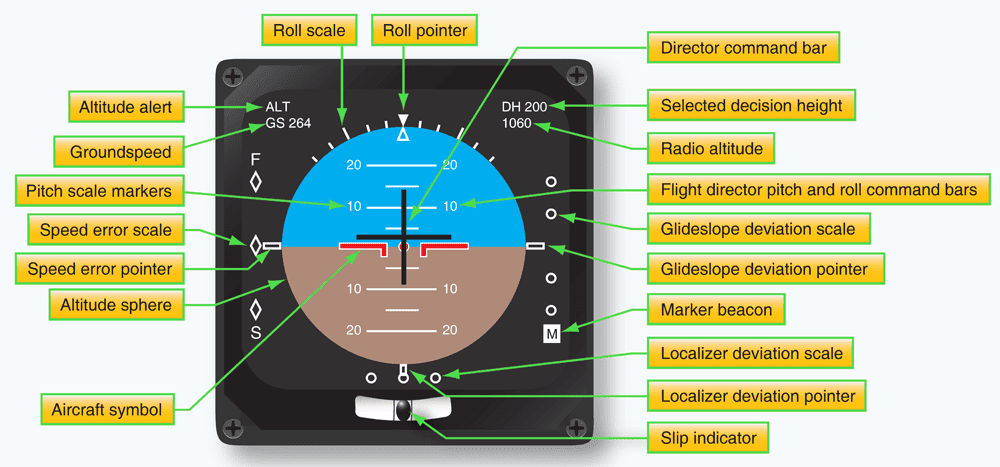
Electronic Attitude Director Indicators (EADI):
- Beyond basic pitch and roll data, can display radio glideslope, localizer data, radar altimeter data, autopilot status, and aircraft indicated airspeed.
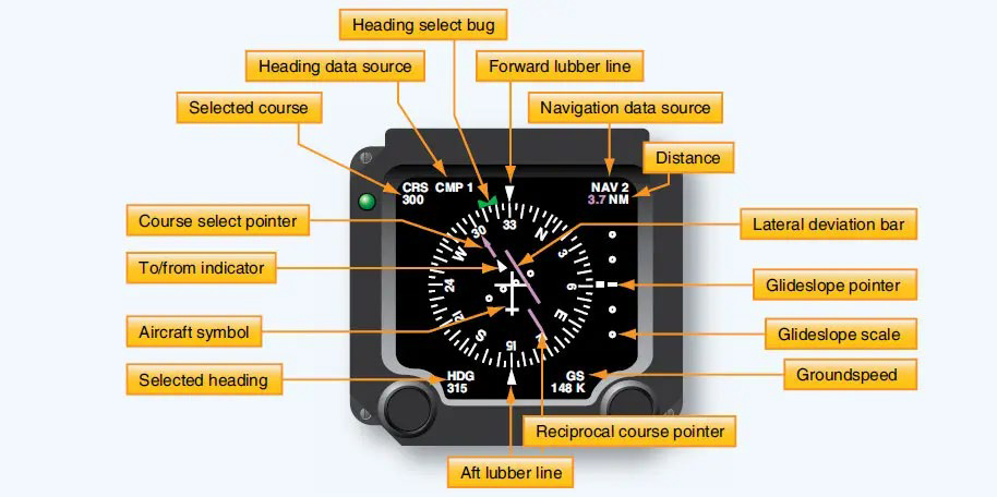
Electronic Horizontal Situation Indicators (EHSI):
- Displays magnetic heading, VOR/INS steering commands, radio glideslope data, DME radio data, and weather radar data.
- Installed in front of pilots to match the standard "T" configuration.
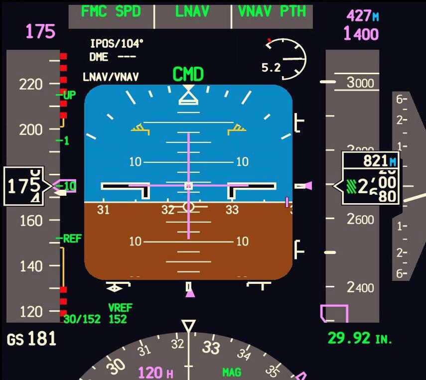
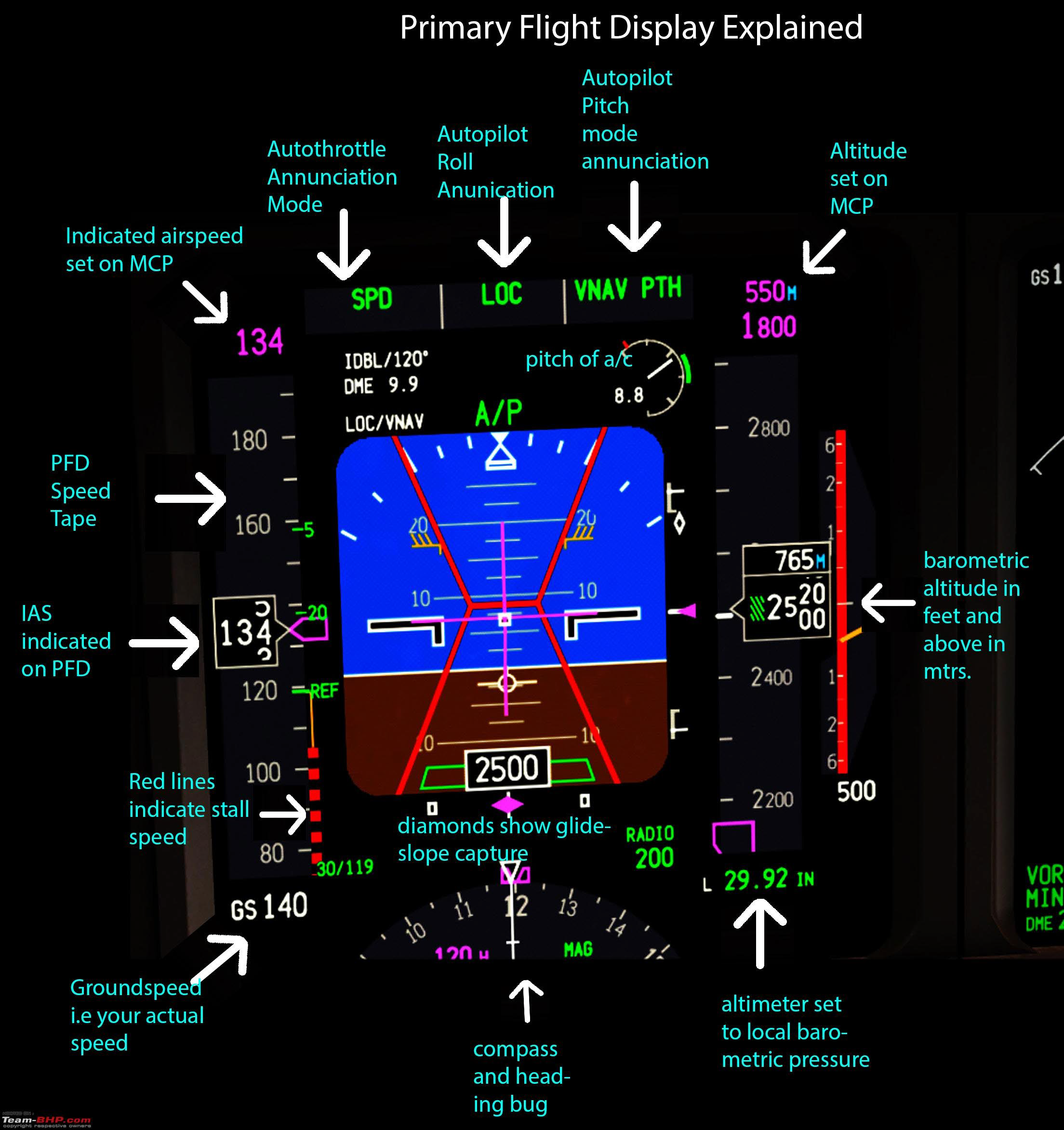
Primary Flight Display (PFD):
- Pilot's primary reference for flight information in aircraft with Electronic Flight Instrument System (EFIS).
- Consolidates information from several electromechanical instruments onto a single electronic display, enhancing situational awareness and reducing pilot workload.
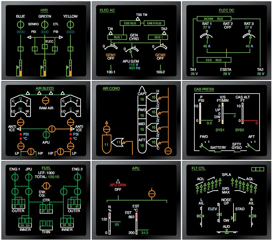
Engine Indication And Crew Alerting System (EICAS):
- Consists of two large CRTs displaying engine indication and crew alerting information.
- Engine indication function displays powerplant instruments, while the crew alerting system monitors various aircraft systems and alerts the crew to faults or abnormal readings.
Computers in Aircraft
- Recent advancements in computer technology have been extensively applied in various aircraft systems.
- Examples include cockpit displays, autopilots, navigational computers, engine controls, among others.
- Modern digital computers are made possible by rapid advances in integrated circuits.
2. Fly-by-Wire (FBW) Systems
- FBW systems use computers to process pilot or autopilot inputs and transmit corresponding electrical signals to flight control surface actuators.
3. BITE Systems (Built-In Test Equipment)
- BITE systems are integrated into major aircraft units to reduce operating costs.
- They offer three primary testing functions:
1. Fault Detection: Continuous monitoring for faults during equipment operation.
2. Fault Isolation: Ability to isolate or bypass faulty equipment.
3. Operational Verification After Defect Repair: Ensuring proper functionality post-repair.
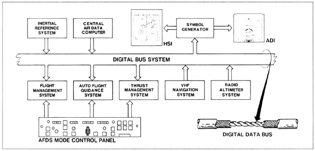
4. Digital Data Transmission
- Rapid and efficient data exchange between aircraft systems is achieved through digital data transmission using digital data buses.
Types of Autopilots
1. Single-axis Autopilot
- Operates the ailerons only, often referred to as a wing leveler.
2. Two-axis Autopilot
- Controls the ailerons and elevator, providing additional control of the aircraft.
3. Three-axis Autopilot
- Operates all three types of control surfaces: ailerons, elevator, and rudder.
Basic Autopilot Operation
1. Sensors or Gyros: Detect changes in aircraft attitude.
2. Amplifier or Computer: Processes sensor signals and sends correction signals to the servos.
3. Servos: Receive signals from the computer to move flight control surfaces.
4. Feedback: Provides signals back to the computer for smooth and precise control.
5. Controller: Located in the cockpit, allows manual commands to change pitch attitude or command a turn.
Automatic Flight Control System (AFCS)
- Three-axis autopilot capable of controlling climbs, descents, cruise flight, and instrument approaches.
- Includes auto-throttle system for automatic control of engine power or thrust.
- Some AFCS autopilots offer auto-land capability, requiring backup systems and high redundancy levels.
Flight Management Systems (FMS)
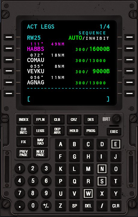
- Feature Flight Management Computers (FMCs) for programming and automatic control of entire flights.
- FMCs can store multiple routes and flight profiles, optimizing fuel consumption and other factors.
Flight Management Computers (FMCs) Functions:
1. Flight Planning: Entire flight programmed using cockpit keyboard.
2. Performance Management: Provides optimal profiles for climb, cruise, descent, and holding patterns.
3. Navigation Calculations: Calculates great circle routes, climb and descent profiles.
4. Auto Tune of VOR and DME: Automatically tunes radios to correct station frequencies.
5. Autothrottle Speed Commands: Displayed on EADI as FAST/SLOW indications.
Flight Control Computers
1. Autopilot Computers
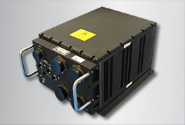
- Three independent autopilot computers ensure redundancy and safety.
- Modern digital computers, more compact and faster than earlier models.
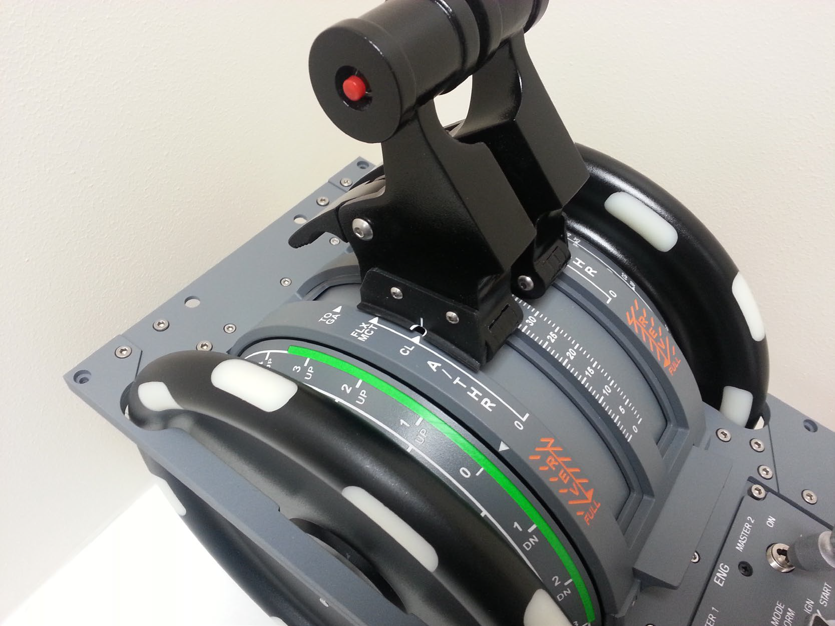
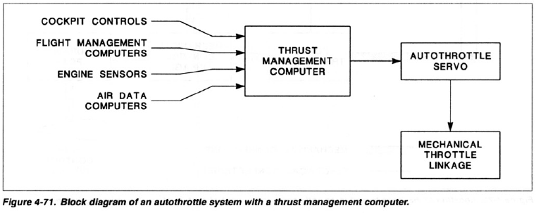
2. Thrust Management Computer (TMC)
- Automatically sets proper thrust level for engines.
- Output servo adjusts throttle linkage based on calculated engine power.
- Sensors monitor engine parameters to prevent exceeding operating limitations (RPM, EPR, EGT).
- Autothrottle system maintains climb rate, indicated airspeed, Mach number, or descent rate.
3. Flight Control Panel
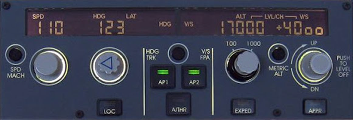
- Contains switches to activate autopilot functions and adjust settings for vertical speed, indicated airspeed (IAS), Mach number, etc.
- Indicator lights indicate different modes of operation.
4. Control Wheel Steering (CWS)
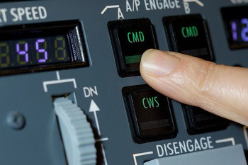
- Operating mode for autopilot alongside command mode.
- In CWS mode, pilot moves controls as in normal flight; autopilot uses this input as guidance.
- Autopilot assists in moving control surfaces while pilot maintains control.
5. Flight Director
- Utilizes some autopilot components but lacks servos.
- Uses sensors and computers to calculate corrections.
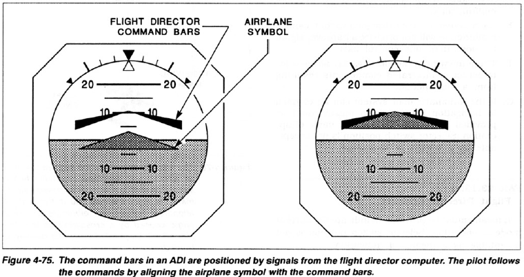
- Displays commands for pilot to follow via command bars on Electronic Attitude Director Indicator (EADI).
