Half bridge circuit
(Page 1 of book)
Basic operation
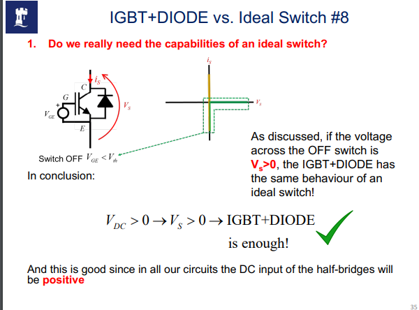
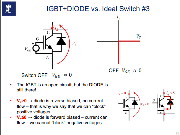
We basically treat the IGBT(transistor ) with a diode as a switch however its slightly different. The ideal switch can do more things —> when its OFF , current will never flow —> HOWEVER, when the IGBT is OFF, current can flow through the diode if its forward biased
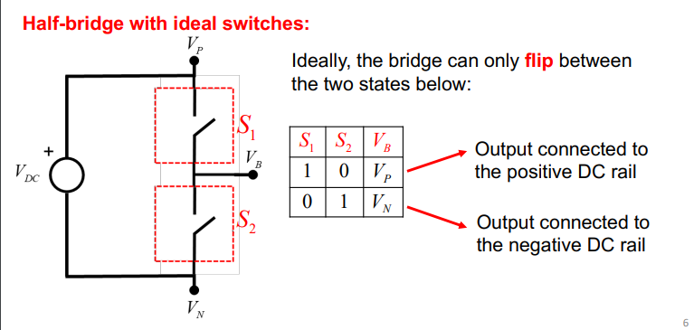
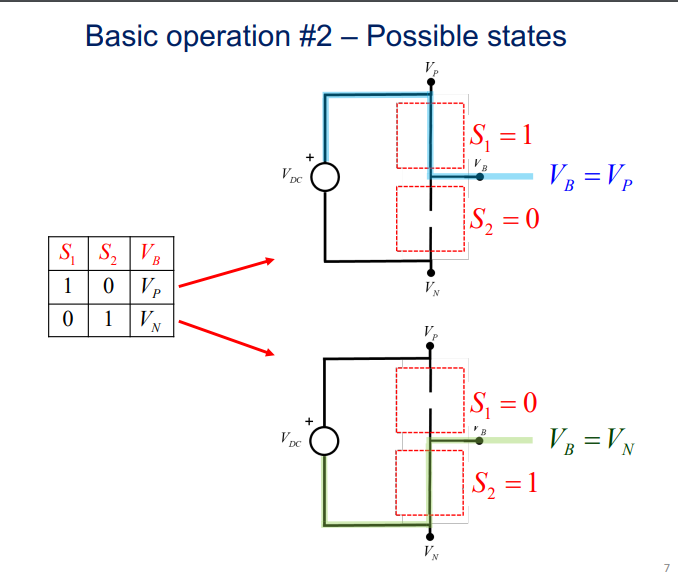
So when S1 is closed and S2 is open then the output is equal to Vp the positive DC rail
and vice versa with S2 Negative voltage DC rail
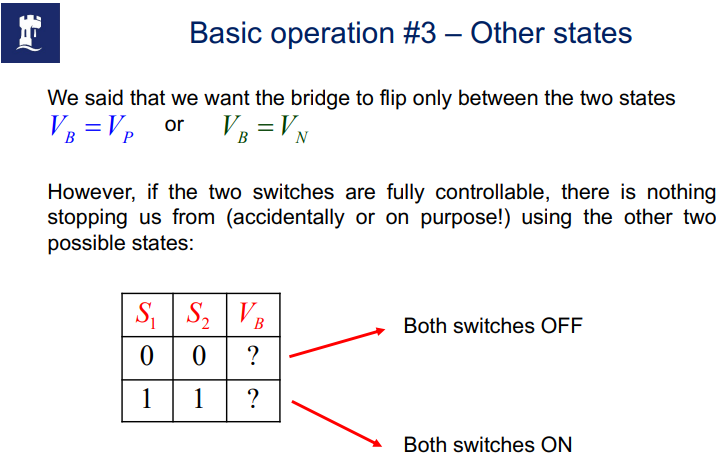
If both switches are ON , also called “shoot-through” state
The input voltage source VDC is short circuited through the switches. Current is limited only by the very low impedance of the connections and of the switches
This is a destructive conditions that MUST be avoided
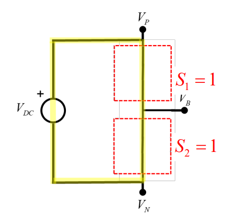
The impact of a shoot through is often hard to see but in most cases it causes irreversible damages to the power switches —> that will need to be replaced
When Both switches are OFF
The output voltage VB is floating, i.e. none of the switches are connected to the DC rails. The value of VB will be imposed by the external circuit connected to the bridge —> This conditions is not a half-bridge with IGBTs (or MOSFETs) with antiparallel diodes
Using this state is essential for practical implementation of the bridge, employing “ dead-times”
Voltage Source Converter (VSC) concept
The choice of voltage reference (the “ground”) with which you refer all the voltages with respect to when you analyze a circuit is arbitrary
You can choose whichever point of the circuit you want
• Even though this is something quite basic, it is often a source of misunderstanding and confusion
• Two very common choices in the half-bridge are:
1. Voltage reference = midpoint of the DC source
2. Voltage reference = negative DC rail
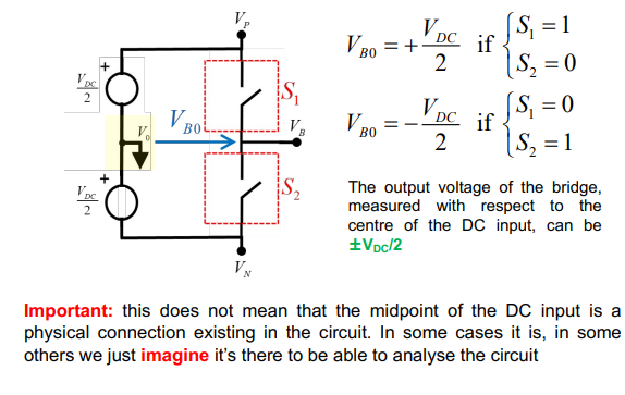
Option 1
Voltage reference = midpoint of the DC source
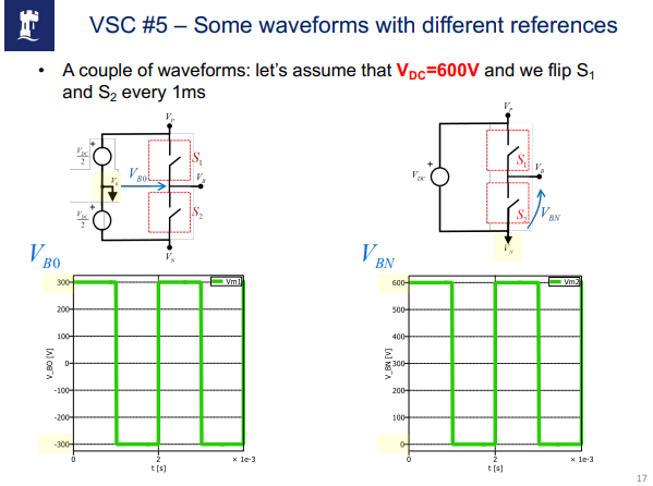
Option 2
Voltage reference = negative DC rail

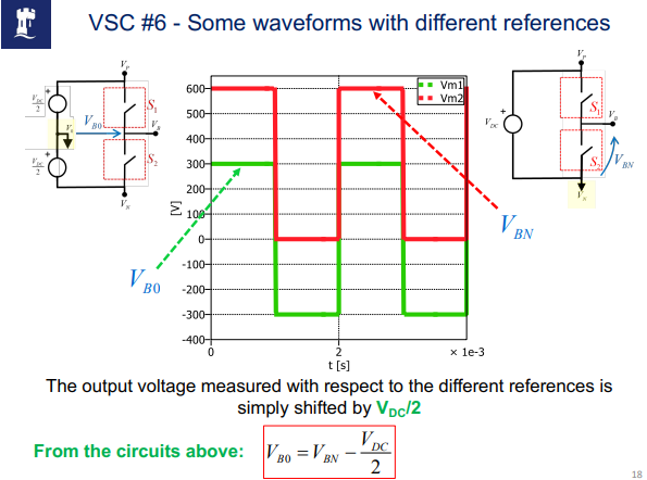
Voltage Source Equivalent Circuit
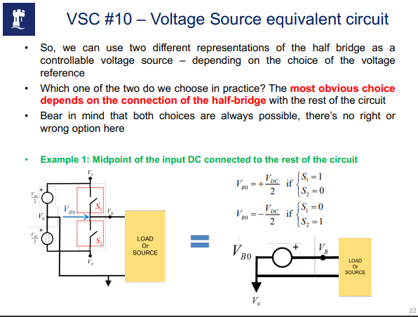
The output voltage VBN (or VBO in the other reference!) is IMPOSED by the half bridge
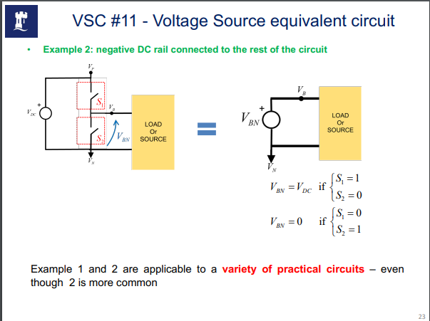
This means that on the output side the half-bridge behaves like a controllable voltage source
VBN only depends on the switching state of S1 and S2, and not on the load (we never needed the load current to write the few equations we wrote!) 19
Hence the name “Voltage Source Converter
Negative Voltage rail
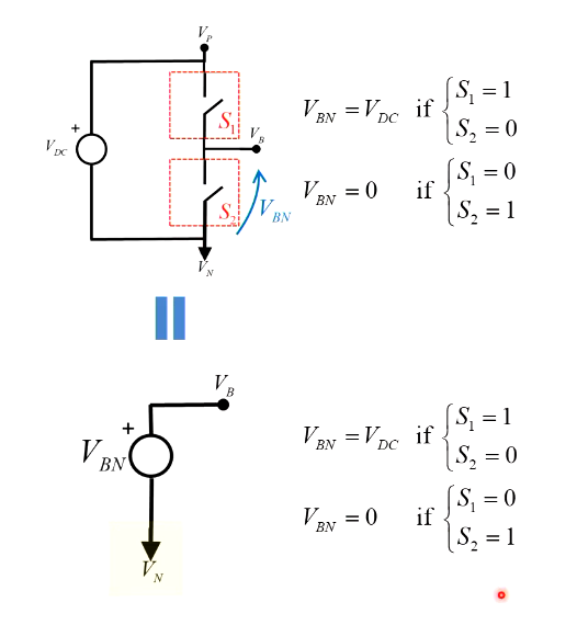
Connected to a load looks like this:
or Mid point of the input DC source as reference
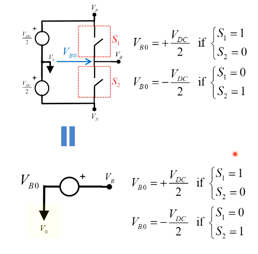
which then when connected to a load looks like this:
(Page 2 of book inserted)
Switches
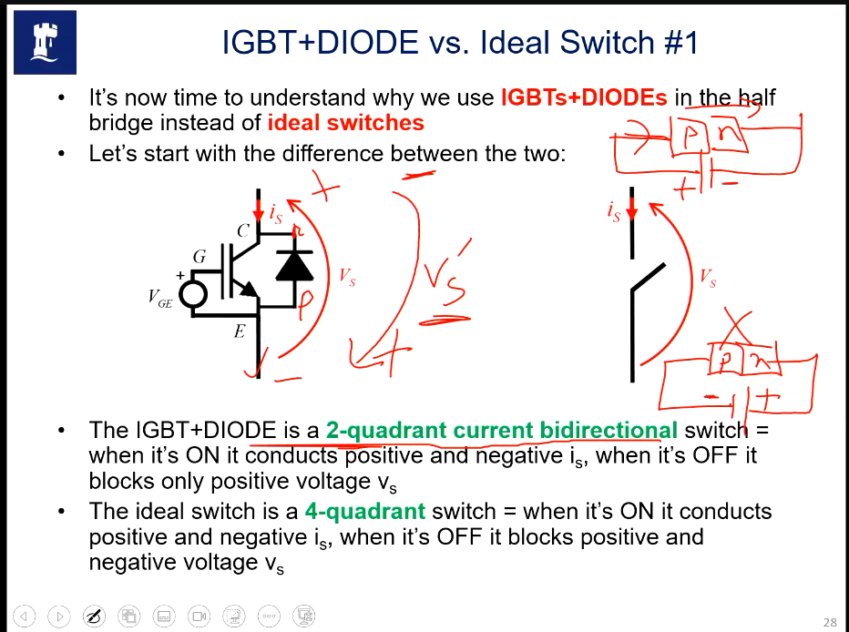
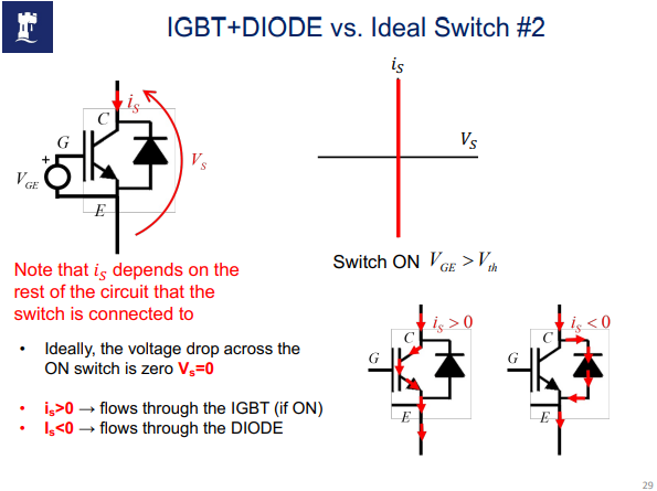
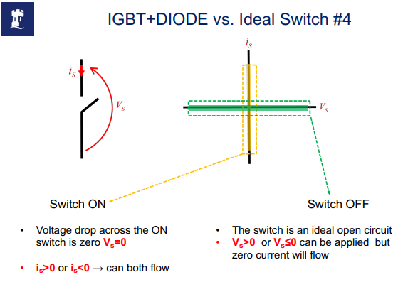
• The IGBT+DIODE behaves the same as an ideal switch during the ON state if we assume ideal IGBT and ideal DIODE – voltage across the switch is zero and current can have both signs
• In the OFF state, the IGBT+DIODE can only block positive voltage, since the diode would be forward biased applying negative voltage
