Exam 2
Introduction to Network Layer
Introduction
The network layer is spilt into two parts: The Data Plane and the Control Plane. Network layer protocols are in EVERY internet device
Function
The function of the network layer is to provide services and protocols that transfer a transport layer’s segment from the sending host to the receiving host. The Network layer handles Forwarding & Routing
Sender: Encapsulates segments into datagrams, passes to the link layer. Sends downs to Link Layer.
Receiver: Delivers segments to transport layer protocol. Sends to up to Transport Layer
Forwarding: Moves packets form router’s input link to appropriate output link
Routing: Determine route taken by packets from source to destination
Data Plane
Deals with local, per-router functions; determines how datagrams arriving on router input port is forwarded to the router’s output port.
Control Plane
Deals with network-wide logic; determines how a datagram is routed along end-end path from source host to destination host
Network Layer: Data Plane
The Data Plane is responsible for moving packets from router’s input to appropriate router output.
Inside a Router
A router consists of Input Ports, Output Ports, Switching Fabric, and a Routing Processor.
Router Parts
Input Port
Deals with queuing if datagrams arrive faster than forwarding rate into switch fabric. Also either Destination-Based Forwarding or Generalized Forwarding
Input Port Queuing: If a switch fabric is slower than input ports combined → queuing may occur at input queues, loss would be due to input buffer overflow
Head of Line (HOL) Blocking: A queued datagram at the front of the queue is preventing others in queue from moving forward
Output Port:
Output Port Queuing: Buffering required when datagrams arrive from switching fabric faster than link transmission rate
Switching Fabrics:
Transfers packet from input link to appropriate output link. Has a switching rate at which packets can be transferred from inputs to outputs. There are three majors types of switching fabrics: Memory, Bus, and Interconnection Network.
Memory Switching: First-generation routers used this by switching under direct control of CPU. The packets were copied to system’s memory. The speed was limited by memory bandwidth.
Bus Switching: A datagram from input port memory to output port memory via a shared bus. Switching speed limited by bus bandwidth (bus contention)
Interconnection Network Switching: Complicated af but exploits parallelism by using multiple switching planes in parallel.
Buffer Management
Involves choosing which packets to add to drop when buffers are full.
Tail Drop: Dropping arriving packet
Priority: Drop/remove on priority basis
Packet Scheduling
Deciding which packet to send next on the link. The types are: FCFS, Priority, Round Robin, and Weighted Fair Queuing.
FCFS
Packets are transmitted in order of arrival to output port (aka FIFO)
Priority Scheduling
Arriving traffic classified, and queued by class (header fields can be used for classification. You would send packet from highest priority queue that has buffered packets. And the FCFS within the same priority class.
Round Robin
Arriving traffic classified, queued by class, then the server cyclically scans class queues, sending one complete packet from each class.
Weighted Fair Queuing
Generalized Round Robin, each class has a weight, and gets weighted amount of service in each cycle.
IP: Internet Protocol
IP Address
There’s a 32-bit identifier associated with each host or router interface.
Interface: Connection between host/router and physical link. Router’s typically have multiple interfaces and hosts typically have one or two interfaces (e.g., wired Ethernet, wireless 802.11
Structure
Subnet Part: Devices in same subnet have common higher order bits
Host Part: Remaining low order bits
Subnet
Device interfaces that can physically reach each other without passing through an intervening router. Devices in the same subnet have common higher-order bits.
CIDR: Classless InterDomain Routing
Subnet portion of address of arbitrary length. This is the part that remains the same between hosts within subnet
a.b.c.d/x (where x is # bits in subnet portion of address)
DHCP: Dynamic Host Configuration Protocol
Host dynamically obtains IP address from network server when it “joins” the network. It can renew its lease on address in use, allows reuse of addresses (while connected) and provides support for mobile users who join/leave network.
Process
Host broadcasts DHCP discover msg (is DHCP out there?)
DHCP server responds with DHCP offer msg (Is this IP address ok?)
Host requests IP address with DCHP request msg (Yes, I want that one)
DHCP server sends address: DHCP ack msg (You got it)
DHCP Return
Allocated IP address
Address of first-hop router for client
Name and IP address of DNS server
Network mask (indicating network versus host portion of address)
DHCP Example
Connecting laptop will use DHCP to get IP address, address of first-hop router, and address of DNS server. The DHCP request message is encapsulated in UDP, encapsulated in IP, and encapsulated in Ethernet.
Ethernet frame broadcasts (dest:FFFFF…) on LAN, received at router running DHCP server.
Ethernet demux’ed to IP, demux’ed to UDP, demux’ed to DHCP
DHCP server formulates DHCP ACK, containing client’s IP address, IP address of first-hop router for client, name & IP address of DNS server. Encapsulated up to Ethernet frame
DHCP server reply is forwarded to client, and demuxing up to DHCP at client
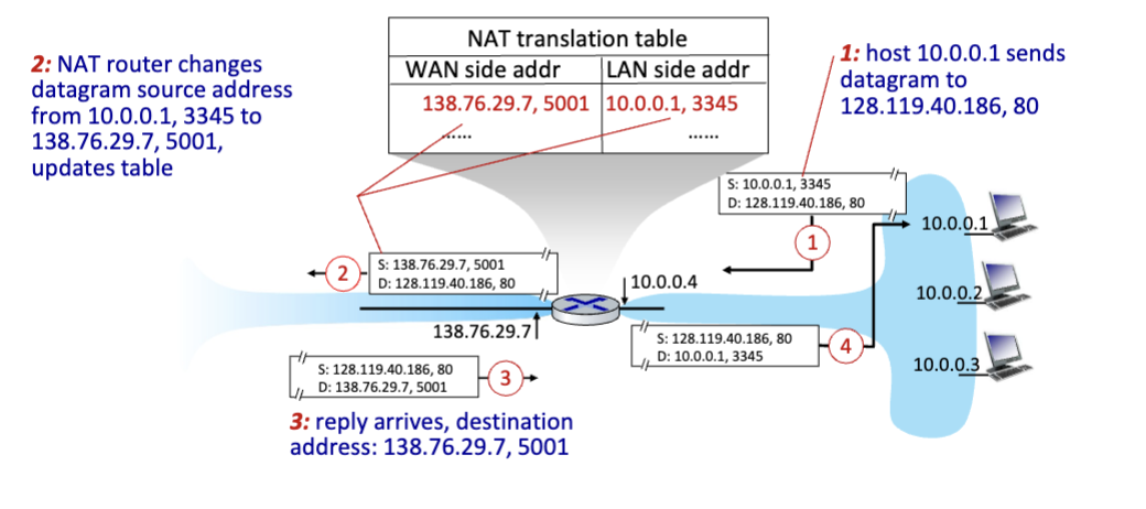
NAT: Network Address Translation
All devices in local network share just one IPv4 (32-bit) address as far as outside world is concerned. All datagrams leaving local network have same source NAT IP address, but different source port numbers
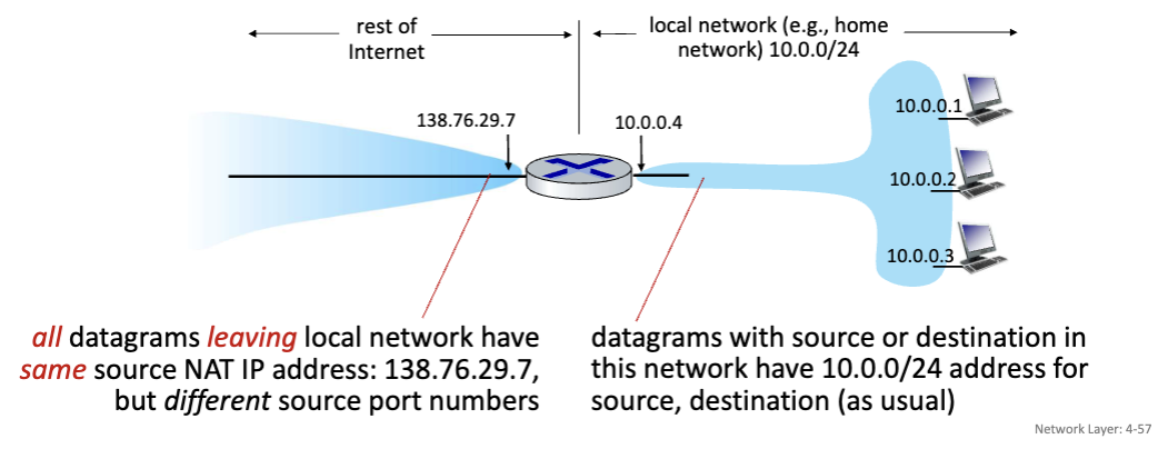
Implementation: NAT router must
Outgoing Datagrams: Replace (source IP address, port #) of every outgoing datagram to (NAT IP address, new port #)
Remember (in NAT translation table) every (source IP address, port #) to (NAT IP address, new port #) translation pair
Incoming Datagrams: Replace (NAT IP address, new port #) in destination fields of every incoming datagram with corresponding (source IP address, port #) stored in NAT table.
IPv6
Initial Motivation: 32-bit IPv4 address space would be completely allocated.
Differences No checksums, no fragmentation/reassembly.
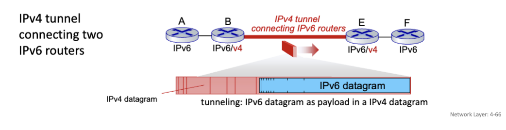
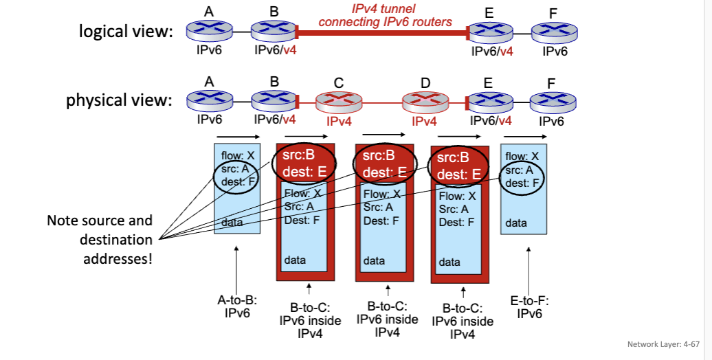
Tunneling
IPv6 datagram carried as payload in IPv4 datagram among IPv4 routers (“packet within a packet)
Generalized Forwarding
Each router contains a forwarding table (aka: flow table). Match + Action: Match bits in arriving packet, take action.
Destination-based Forwarding: Forward based on dest. IP address
Generalized Forwarding: Many header fields can determine action and many actions are possible (drop/copy/modify/log packet)
Flow Table
Flow: Defined by header field values
Generalized Forwarding: Simple packet-handling rules
Match: Pattern values in packet header fields
Actions: for matched packet: drop, forward, modify, matched packet or send matched packet to controller
Priority: Disambiguate overlapping patterns
Counters: #bytes and #packets
Network Layer: Control Plane
The Control Plane is responsible for determining the route taken by packets from source to destination. There are two approaches to structuring network control plane: Per-Router Control, and Logically Centralized Control (SDN)
Per-Router Control Plane: Individual routing algorithm components in each and every router interact in the control plane
Software-Defined Networking Control Plane: Remote controller computes, and installs forwarding tables in routers
Routing Protocols
Link State Algorithms: Global algorithms where all routers have complete topology, link cost info.
Distance Vector Algorithms: Iterative process of computation, exchange of information with neighbors. Routers initially only know link costs to attached neighbors.
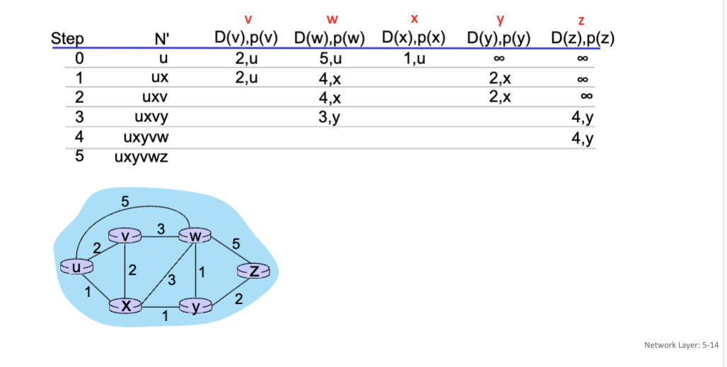
Dijkstra’s Link-State Routing Algorithm
Centralized: Network topology, link costs known to all nodes (accomplished via “link state” broadcasts. All nodes have same information
Computes least cost paths from one node (“source”) to all other nodes (giving forwarding table for that node)
Iterative: After k iterations, know least cost path to k destinations.
Notation
C_x, y: Direct link cost from node x to y; = infinity if not direct neighbors
D(v): Current estimate of cost of least-cost-path from source to destination v
p(v): Predecessor node along path from source to v
N’: Set of nodes whose least-cost-path is definitively known
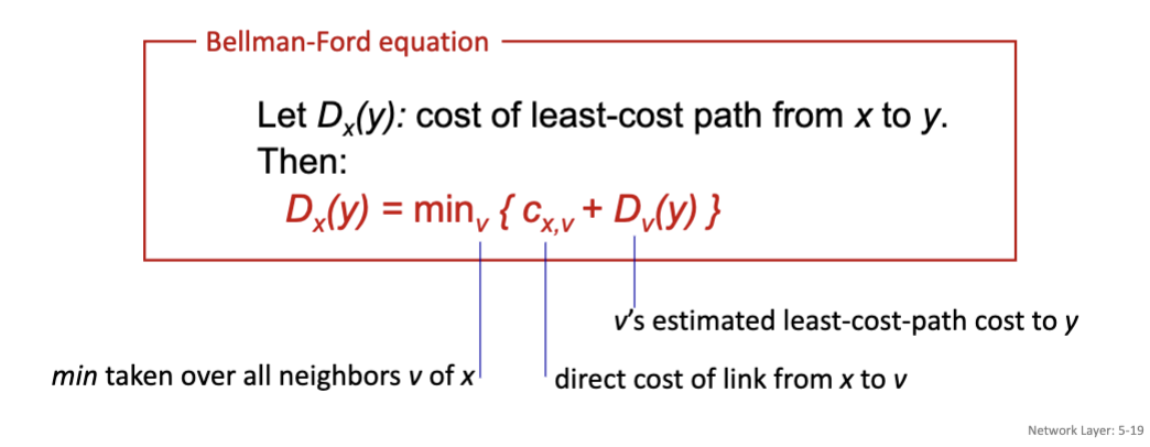
Bellman-Ford Distance Vector Algorithm
Based on Bellman-Ford equation (Dynamic Programming)
Equation
Comparison of LS and DV Algorithms
Speed of Convergence:
LS: Relatively fast
DV: Convergence time varies (count-to-infinity problem)
Robustness:
LS: Router can advertise incorrect link cost, each router computes only its own table
DV: Router can advertise incorrect path cost
Intra-ISP Routing: OSPF
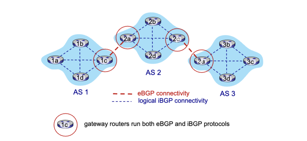
Aggregating routers into regions known as “Autonomous Systems” (AS) (aka “domains”). Two types: Intra-AS (aka intra-domain), and Inter-AS (aka inter-domain
Intra-AS
Routing within same AS (“network”). All routers in AS must run same intra-domain protocol. There’s a Gateway Router at the edge of its own AS that has links to routers in other AS’es
OSPF: Open Shortest Path First
A link-state routing algorithm that is ‘open’, meaning it’s publicly available
Inter-AS
Routing amongst AS’es. Gateways perform inter-domain routing (as well as intra-domain routing). Uses Dijkstra’s algorithm to compute forwarding table
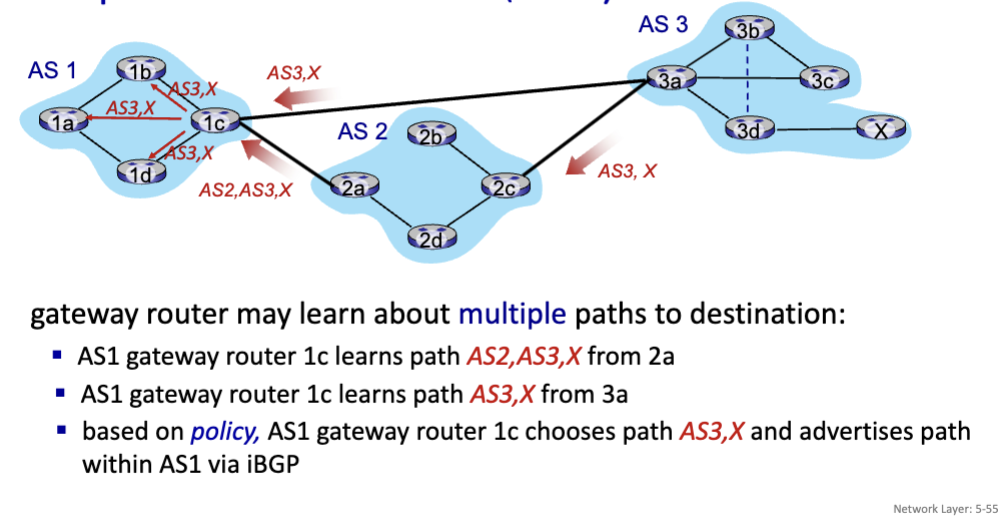
BGP: Border Gateway Protocol
The de facto inter-domain routing protocol (glue that holds the internet together). Allows subnet to advertise its existence, and the destinations it can reach to the rest of the Internet. BGP provides each AS a means to:
eBGP: Obtain subnet reachability information from neighboring ASes.
iBGP: Propagate reachability information to all AS-internal routers.
BGP Session: Two BGP routers exchange BGP messages over semi-permanent TCP connection
BGP Messages: Messages exchanged between peers over TCP connection
OPEN: opens TCP connection to remote BGP peer and authenticates sending BGP peer
UPDATE: advertises new path
KEEPALIVE: keeps connection alive in absence of UPDATES; also ACKs OPEN request
NOTIFICATION: reports errors in previous msg; also used to close connection
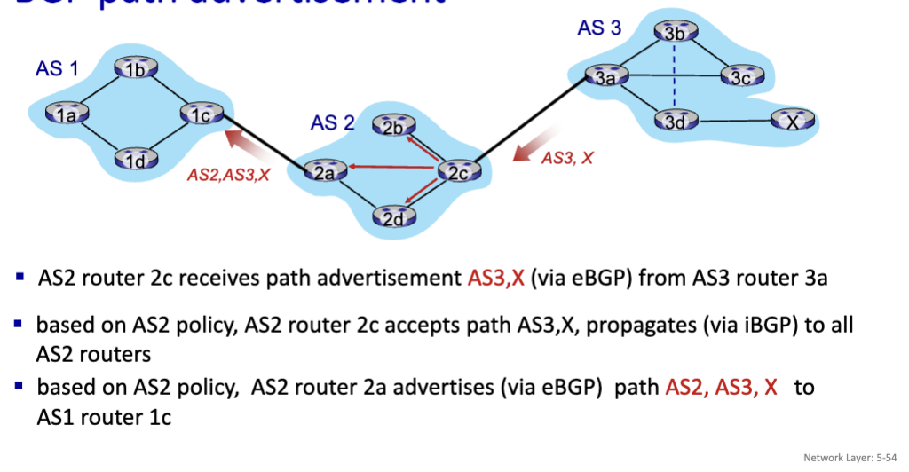
BGP Advertisement: Prefix + Attribute
Prefix: Destination being advertised
Attributes:
AS-PATH: List of ASes through which prefix advertisement has passed
NEXT-HOP: Indicates specific internal-AS router to next-hop AS
Policy-Based Routing: Gateway receiving route advertisement uses import policy to accept/decline path (e.g., never route through this particular AS, maybe a rival company). AS policy determines whether to advertise path to other neighboring ASes.
SDN: Software-Defined Networking Control Plane
Remote controller computers, and installs forwarding tables in routers. Why a logically centralized control plane?
It’s easier to management a network, greater flexibility of traffic flows. Table-based forwarding allows programming routers
Ig you wanted to change traffic flow using the traditional routing, you would have to re-define link weights, which can be tedious. But, with SDNs this is possible.
Data-Plane Switches: Fast and simple commodity switches implementing generalized data-plane forwarding
SDN Controller: Maintains network state information and interacts with network control applications above and network switches below
Network-Control Apps: The brains of control, implements control functions using lower-level services (API provided by SDN controller)
Link Layer
The link layer has the responsibility of transferring a datagram from one node to a physically adjacent node over a link. Encapsulates a datagram from the network layer to a “Frame”, adding a header and a trailer. The headers contain a MAC address to identify source, and destination. The link layer is implemented in every host in the NIC (network interface card) or on a chip
Interfaces: Sender encapsulates datagram into frame, adds error checking bits, reliable data transfer, and flow control. The receiving side looks for errors, reliable data transfer, and flow control; extracts datagram, passes to upper layer at receiving side
MAC Addresses
Used “locally” to get a frame from one interface to another physically-connected interface (same subnet, in IP-addressing sense). It’s a 48-bit MAC address burned into NIC ROM and sometimes software settable.
Each interface on LAN has a unique 48-bit MAC address
(similar to a SSN as it’s specific to you and doesn’t change)
ARP: Address Resolution Protocol
Used to determine an interface’s MAC address if you know it’s IP address. Each IP node (host, router) on LAN has a table:
< IP address; MAC address; TTL >
Time to Live (TTL) is usually around 20 mins, after that, the address mapping will be forgotten
Process: A wants to send datagram to B
A broadcasts ARP query, containing B’s IP address and a destination MAC Address of FF-FF-FF-FF-FF-FF (all ones). All nodes on LAN receive the ARP query.
B sees the IP address from the query matches is’s own, so it replies to A with ARP response, giving it’s MAC address
A receives B’s reply, and adds B entry into its local ARP table
Routing to Another Subnet
A creates IP datagram with IP source A, and destination B, and creates a link-layer frame containing A-B IP datagram.
R’s MAC address is the frame’s destination (this is the gateway router that is known to A when it first joined the network through DHCP)
Frame is sent from A to R
Frame is received at R, the datagram is removed, and passed up to IP
R determines the outgoing interface, passes the datagram with IP source A, and destination B to link layer
R Creates link-layer frame containing A-to-B IP datagram. The frame destination is B’s MAC address. Transmits link-layer frame.
Error Detection
Parity Checking
Single bit parity: Detects single bit errors. Even Parity means you set a parity bit so there is an even number of 1’s. So it string of bits has five 1’s, then the parity bit would be 1 to make the string have an even number of bits. If it had six 1’s, then the parity bit would be 0 because the string already had an even number of 1’s
The downside is that it can only detect one error. If there are multiple, you wouldn’t know. Also, if there are an even number of error, it also wouldn’t know.
Two-Dimensional Bit Parity: Detects and corrects single bit errors. Same as single bit parity except you put the string of bits into a table and calculate the parity bits for each row and each column. You’ll be able to detect an error and correct single bit errors.
Internet Checksum
The goal is the detect errors in transmitted segments.
Sender: The sender treats contents of UDP segment as a sequence of 16-bit integers. The checksum is the addition (one’s complement) of the segment content. That value is put into UDP checksum field.
Receiver: The receiver computes checksum of received segment and checks if computed checksum equals the checksum field value - if its not equal, then error. Even if equal, doesn’t mean there isn’t an error.
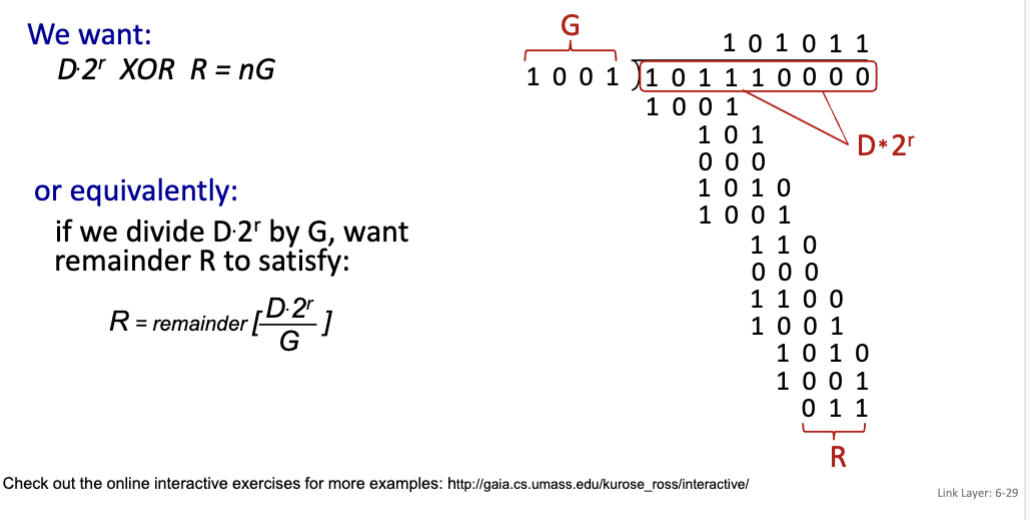
Cyclic Redundancy Check (CRC)
A more powerful error-detection coding. The goal is to choose r CRC bits, R, such that <D, R> is exactly divisible by G (mod 2). The receiver knows G, and divides <D, R> by G → if the remainder is non-zero, then error detected. CRC can detect all burst errors less than r+1 bits. Used in Ethernet, 802.11 WiFi.
D: Data bits
G: Bit pattern (or generator), of r+1 bits
Multiple Access Protocols
There are two types of links: point-to-point and broadcast. There are three broad classes of protocols: Channel Partitioning, Random Access, and Taking Turns.
Point-to-point: Link between Ethernet switch, host
Broadcast (shared wire or medium): Old fashioned Ethernet
Channel Partitioning
Dividing the channel into smaller “pieces” (Time slots or frequency). Then allocate the piece to node for exclusive use.
TDMA: Time Division Multiple Access
Access to channel in “rounds”. Each station gets fixed length slot in each round. (Length = packet transmission time)
Unused slots go idle
FDMA: Frequency Division Multiple Access
Channel spectrum is divided into frequency bands. Each station is assigned a fixed frequency band.
Unused transmission time in frequency bands go idle
Random Access
The channel is not divided, and allows for collision, tries to recover from collisions. When a node has a packet to send, it transmits at full channel data rate. If there are two or more transmitting nodes, then there’s a collision.
Slotted Aloha: All frames are the same size, time is divided into equal size slots (time to transmit 1 frame). Nodes start to transmit only at slot beginning. (Operation) When node obtains a fresh frame, it transmits it in the next slot, if there’s no collision, the node can send new frame in the next slot. If there is a collision, the node retransmits the frame in each subsequent slot with probability p until success. Max Efficiency = 1/e = 0.37
Pure Aloha: unslotted Aloha that is simpler to implement. When the frame first arrives, it transmits it immediately. The collision probability is increased. Efficiency = 0.18 (half of slotted)
CSMA (Carrier Sense Multiple Access): Simple CSMA is where a frame listens before it transmits. If the channel sensed is idle: transmit the entire frame. If the channel sensed is busy: defer transmission. Collisions can still occur due to propagation delay. It may not have “heard” the other just starting transmitting just yet due to delay. During collision, the entire packet transmission time to wasted
CSMA/CD (CSMA with Collision Detection): Collisions are detected within a short time, colliding transmissions are aborted, reducing channel wastage. Ethernet uses this
NIC receives datagram, creates frame
If NIC senses channel:
If idle: start frame transmission
If bust: wait until channel idle, then transmit
If NIC transmits entire frame without collision, NIC is done
If NIC detects another transmission while sending: abort, send jam signal, go to step 1
After aborting, NIC enters binary backoff: after mth collision, NIC choose K at random. NIC waits K*512 bits, returns to step 2. More collisions: longer backoff interval
Taking Turns
Nodes take turns, but nodes with more to send can take longer turns. Used in bluetooth
Polling: Maser node “invites” other nodes to transmit in turn. Typically used with “dumb” devices. Suffers from single point of failure (master)
Token Passing: Control token passed from one node to next sequentially. Suffers from single point of failure (token)
LANs
Ethernet
Dominant wired LAN technology and the first widely used LAN technology. It’s simple and cheap and keeps up with speed race.
Connectionless: No handshaking between sending and receiving NICs
Unreliable: Receiving NIC doesn’t send ACKs or NAKs to sending NIC
Switches
Ethernet Switch
A switch is a link-layer device that stores, and forwards Ethernet frames. They examine incoming frame’s MAC address, selectively forwards frame to one-or-more outgoing links when frame is to be forwarded on segment
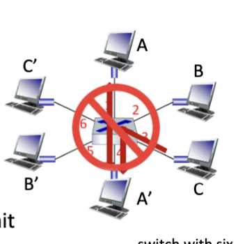
Multiple Simultaneous Transmissions
Host have dedicated, direct connection to switch. A to A’ and B to B’ can transmit simultaneously without collision BUT A to A’ and C to A’ can’t.
Self-learning
Switch can learn which hosts can be reached through which interfaces. When frame is received, the switch learns location of sender and records sender/location pair in switch table
Frame Filtering/Forwarding
When the frame is received at switch:
Record incoming link (MAC of sending host)
Index switch table using MAC destination
If entry found for destination
If destination on segment from which frame arrived
Drop frame
Else, forward frame on interface
else flood (forward on all interfaces except arriving interface)
If frame destination location is unknown: flood (send to all except arriving interface)
If destination location is known, selectively send on just one link
Datacenters
Server racks
20- 40 server blades: hosts
Top of Rack (TOR) switch
one per rack
40-100Gbps Ethernet to blades
Tier-2 switches
connecting to ~16 TORs below
Tier-1 switches
connecting to ~16 T-2s below
Border router
Connections outside datacenter
Day in Life
First connect to LAN, use DHCP as app layer, encapsulated in UDP, encapsulated in IP, and then in Ethernet. Ethernet frame broadcast on LAN for DHCP server. Frame demuxed to DHCP server.
Server DHCP ACK containing clients IP, IP of first hop router, and DNS server. Encapsulates down to Ethernet. Frame forwarded and demuxed at client.
before HTTP request, we need IP address of google: we’ll use DNS.
DNS query created, encapsulated in UDP, IP, Ethernet. Frame sent to router, but we need MAC address.
ARP query broadcast, received by router, gives ARP reply giving MAC address. Client now knwos MAC of first hop so can send frame containing DNS query.
IP datagram forwarded to 1st hop router
IP datagram forwarded from campus network to comcast network
DNS replies to client of IP address of google
TCP socket: to send HTTP request, client opens TCP socket to web server, TCP SYN segment routed to web server, web server responds with TCP SYNACK, TCP connection established
HTTP request sent into TCP socket, IP datagram containing HTTP request routed to google. Web server replies with HTTP reply, IP datagram containing HTTP reply routed back to client
Exam Examples
IP Addressing CIDR
DHCP client-server scenario
NAT Table
IPv6 to IPv4 Tunneling
Match + Action
Dijkstra’s Algorithm
Bellman-Ford
BGP Path Advertisement
Checksums
Bit Parity
CRC
Channel Partitioning, Random Access, Taking Turns
TDMA
Slotted Aloha
Pure Aloha
CSMA
CSMA/CD
MAC Addresses
ARP Table
Routing to Another Subnet
Day in the life of web request