I-V Characteristics
I-V Graphs Show How Resistance Varies
The term ‘I-V characteristic’ refers to a graph which shows how the current (I) flowing through a component changes as the potential difference (V) across it is increased.
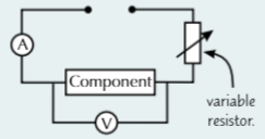
You can investigate the I-V characteristic of a component using a test circuit like this one:
Use the variable resistor to alter the potential difference across the component and the current flowing through it, and record V and I.
Repeat your measurements and take averages to reduce the effect of random errors on your results.
Plot a graph of current against potential difference from your results. This graph is the I-V characteristic of the component.
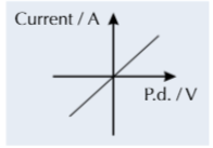
The I-V Characteristic for a Metallic Conductor is a Straight Line
At constant temperature, the current through a metallic conductor, e.g. a wire or a resistor, is directly proportional to the potential difference.
The fact that the characteristic graph is a straight line through the origin tells you that the resistance doesn’t change — it is equal to 1/gradient .
The shallower the gradient of the characteristic I-V graph, the greater the resistance of the conduct.
Metallic conductors are ohmic — they have constant resistance provided their temperature doesn’t change
The I-V Characteristic for a Filament Lamp is Curved
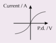
The characteristic graph for a filament lamp is a curve, which starts steep but gets shallower as the potential difference rises.
The filament is a lamp is just a coiled up length of the metal wire, so you might think it should have the same characteristic graph as a metallic conductor.
However, current flowing through the lamp increases its temperature, so its resistance increases.
The Resistivity of a Metal Increases with Temperature
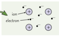
Charge is carried through metals by free electrons in a lattice of positive ions.
Heating up a metal makes it harder for electrons to move about. The lattice of ions vibrates more when heated, meaning the electrons collide with them more frequently, transferring some of their kinetic energy into forms.
When kinetic energy is lost by the individual electrons, their speed and therefore the mean drift velocity decreases. As current is proportional to drift velocity, (I = nqvA) this means the current in the wire decreases so its resistance (and its resistivity, as it’s dimensions haven’t changed) increases.
Semiconductors are Used in Sensors
Semiconductors have higher resistivity than metals because there are fewer charge carriers available.
However, if energy is supplied to some types of semiconductor (e.g. by increasing their temperature), more charge carriers are released, so the current increases (as I = nqvA) and their resistance and resistivity decrease.
This means that they can make excellent sensors for detecting changes in their environment. You need to know about three semiconductor components — thermistors, LDRs and diodes.
Like metals, increasing the temperature of semiconductors increases their lattice vibrations, reducing the mean drift velocity of electrons. But this effect is dwarfed by the effect of releasing more charge carriers with increasing temperature.
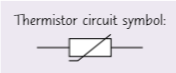
The Resistance of a Thermistor Depends on Temperature
A thermistor is a resistor with a resistance that depends on its temperature. You only need to know about NTC thermistors — NTC stands for ‘Negative Temperature Coefficient’. This means that the resistance decreases as the temperature goes up.
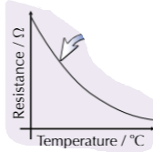
The resistance of an NTC thermistor decreases with temperature.
The characteristic I-V graph for an NTC thermistor looks like this: As the voltage increases, the current increases. More current leads to an increase in temperature and so a decrease in resistance. This in turn means more current can flow, so the graph curves upwards.
Warming the thermistor gives more electrons enough energy to escape from their atoms. This means that there are more charge carriers available, so the current increases and the resistance decreases (R= V/I) .
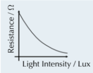
The Resistance of an LDR Depends on Light Intensity
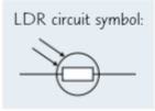
LDR stands for Light-Dependent Resistor. The greater the intensity of light shining on an LDR, the lower its resistance.
The explanation for this is similar to that for the thermistor. In this case, light provides the energy that releases more electrons. This means more charge carriers, which means a higher current and a lower resistance.
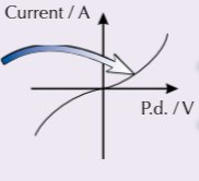
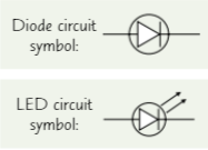
Diodes Only Let Current Flow in One Direction
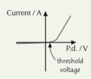
Diodes (including light- emitting diodes (LEDs)) are designed to let current flow in one direction only. You don’t need to be able to explain how they work, just what they do.
Forward bias is the direction in which the current is allowed to flow — it’s the triangle points in the circuit symbols on the right.
Most diodes require a threshold voltage of about 0.6V in the forward direction before they will conduct.
In reverse bias, the resistance of the diode is very high and the current that flows is very tiny.
Practice Questions
Q1 If an I-V graph is a straight line through the origin, what does this tell you about the resistance?
Q2 Draw an I-V characteristic graph for a resistor.
Q3 What is an LDR?
Q4 Draw an I-V characteristic graph for a diode. Label the areas of forward bias and reverse bias.
Exam Question
Q1 a) Sketch a characteristic I-V graph for a filament lamp.
b) Explain how increasing the voltage across a filament lamp affects its resistance with reference to the mean drift velocity of electrons in the lamp.
c) Explain how the resistance of an NTC thermistor with temperature.