MOD 4 - Digital Imaging Process
Computed Radiography
= exposure of an imaging receptor in a cassette and a computer system for image processing
both are digital (not film)
uses IP
CR Imaging Receptor / Cassette
= lightweight tight plastic container that protects the digital imaging plate from damage from handling
backed by a thin sheet of Al that absorbs x-rays
front or tube side of the cassette is constructed of a radiolucent carbon fibre
also contains an antistatic material that protects against static electricity build up, dust collection and mechanical damage to the IP
Cassette
the backside contains brackets and hinges
only use front side when imaging
main function is to protect the IP from damage
however, it can’t protect the IP from light damage bc its not sensitive to light
CR Imaging Plate
capable of storing an image formed by the incident x-ray photon (a single x-ray in the primary x-ray beam that is traveling towards the interested part) that excites the photostimulable phosphors (PSP: materials that store energy from X-rays and gamma rays and release it as light when stimulated)
Composition of IP
PSP are deposited in layers on the imaging plate
common PSP materials:
europium activated fluorohalide crystals
cesium bromide crystals
Europium: element that allows for energy storage
*ability of the PSP to retain energy is time limited, THEREFORE IPs should be processed soon after exposure *
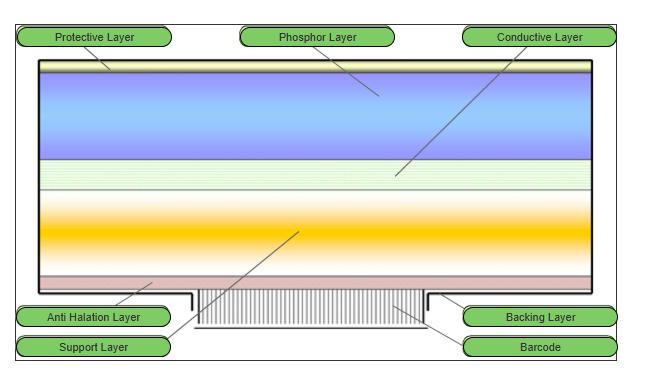
CR IP Layers
Protective Layer
thin, tough, clear plastic top layer
protects the underlying phosphor layer and rest of IP
improves the signal to noise ratio of an image
Phosphor layer / F-Center / storage phosphor / colour layer
active layer of the IP as it traps/stores the -e when struck by x-rays
may contain a dye to absorb the stimulating light to prevent as much spread
phosphor gradually releases stored energy naturally (phosphorescence) but this is acc during processing by the exposure to intense infrared laser light (photostimulated luminescence - PSL)
made up of barium fluorohalide or cesium bromide crystals, europium azelcleaer (?)
Light reflective layer
below phosphor layer and reflects light
reflects and focuses the light heading to the back of the IP to the crystal structure in the phosphor layer
energy is bounced back to the crystal structure (phosphor layer)
Conductive Layer
absorbs and reduces static electricity that can cause light emission (light emission can produce artifacts or a false image)
Supportive Layer
semi-rigid material that gives the imaging plate some strength
constructed of a polymethylene terephthalate (PET) base- a strong, pliable plastic
Colour or Anti-halation Layer
consists of a blue tinted dye that absorbs unwanted stimulating laser light while reflecting emitted light
Backing Layer
soft, plastic layer constructed of a soft polymer that also serves to protect the base of IP from damage during processing (as the IP is removed from the cassette to be processed)
Barcode
allows the user to match the image information with the RIS patient demographics
CR Image Formation Steps
Expose
phosphors of the IP retains energy based on the frequency and number of photon interactions
Stimulate
cassette is inserted into the CR reader
the IP is removed from the IR
a laser scans the IP to release the energy stores as bursts of light (photostimulable luminescence- PSL)
light emitted is converted into an electrical signal
Read
electrical signal is detected by PMT and measured, then converted to a digital signal by ADC (analog-to-digital converter) and digitized to be displayed on the workstation monitor
Erase
then the IP is erased by exposure to intense light that releases any retained energy (causes it to return to ground-state energy level)
not all areas can be erased, some portions will be missed
CR receptor is ready for reuse
CR Processor / Reader
= designed to process a single cassette perhaps within a radiography room or multiple cassettes in a hub of multiple x-ray rooms
CR Processing Steps
exposure of CR plate
scan barcode of CR plate at workstation to associate to patient exam
insert plate into CR processor
imaging plate processed
IP removed, scanned by laser,
light emitted detected by photomultiplier tube (PMT)
PMT analog signal converted to digital signal (analog-to digital-conversion)
digital signal transmitted to monitor viewing station
IP exposed to intense light to release any residual energy stored in phosphors
IP inserted into cassette and ejected from CR processor, ready to reuse
dark features = energy absorbed by IP
white features = energy blocked, absorbed by bone/parts
Direct Radiography
= more streamline, does not require a separate processing step
both digital
flat-panel detectors
uses a large area active-matrix array of electronic components
two image production methods for DR
direct conversion
uses photoconductor
indirect conversion
scintillator material
high sensitivity of CsI → significant exposure reductions → substantially reduce patient dose
Three elements to all digital radiography
Capture element (crystal structures that absorb energy, creates light)
Coupling element (layer that binds the light produced to a collection system)
Collection element (reads the light produced which is read by chips or in an amorphous silicon)
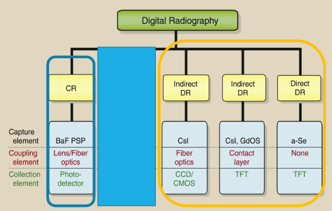
Indirect DR Detectors
= system absorbs x-rays and first converts it to light before creating a digital signal
Scintillating (light producing) materials (cesium iodide) are used to convert photon energy into visible light
The light is detected and converted to an electrical signal that is sent to the computer for processing
Two methods for this light conversion
charge-coupled device (CCD)
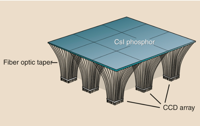
thin-film transistor (TFT)
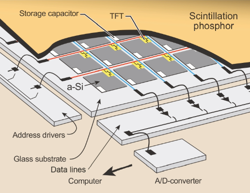
Direct DR Detectors
no scintillation layer (no CsI) involved, therefore no light-emitting process that is detected and amplified
x-ray photon energy/exit radiation is directly (by a-Se) converted to electrical energy/electrical charges
this system relies on a layer of amorphous selenium (a-Se) for both the capture element and the coupling element
Electrical signals are sent to the ADC for digitization
Post Processing Functions
image control quality
includes a thorough critique of each image, as well as post-processing if necessary
Examples of Post Processing
annotation (markers, position)
zoom (zoom data is not saved, just for viewer instance)
image flip
image rotation (to correct orientation)
window level/width (adjusting the grey scales and contrast to improve visualization, this adjusted image must not be sent to PACS for diagnosis)
measurement (for length or volume of a structure)