Physics O-levels notes
Measurements
1. Physical Quantities, Units & Measurements
1.1 Physics
Physics is the study of matter, energy, their properties & relationships with each other in the fields of General Physics, Thermal Physics, Light, Waves & Sound, Electricity & Magnetism & Radioactivity.
1.2 Physical Quantities
A physical quantity is a quantity that can be measured. It consists of a numerical magnitude & a unit.
1.2.1 SI Units
There are 7 basic physical quantities, each quantity has an SI unit (See more in O-level chemistry physical quantity notes).
Base Quantity | SI Unit | Symbol for SI Unit |
|---|---|---|
length | metre | m |
mass | kilogram | kg |
time | second | s |
electric current | ampere | A |
thermodynamic temperature | kelvin | K |
amount of substance | mole | mol |
1.2.2 SI Unit Prefixes
There are prefixes for SI units for convenience in expressing large or small quantities.
Factor | Prefix | Symbol | |
|---|---|---|---|
Multiples | 1012 | tera- | T |
109 | giga- | G | |
106 | mega- | M | |
103 | kilo- | k | |
Sub-multiples | 10-1 | deci- | d |
10-2 | centi- | c | |
10-3 | milli- | m | |
10-6 | micro- | µ | |
10-9 | nano- | n |
1.2.3 Standard Form
Physical quantities can be expressed in standard form, example 9.9 x 10⁹ m. Refer to math o-level revision notes.
1.3 Measuring Physical Quantities
1.3.1 Measurement of Length
SI unit for length is metre (m).
Instrument | Measuring Range | Smallest Division | Example of Usage | Recording Measurements |
measuring tape | zero to several metres | 0.1 cm or 1 mm | a person's waist | to the nearest mm |
metre rule | zero to one metre | height of a table | ||
digital callipers | zero to 15 centimetres | 0.001 cm or 0.01 mm | diameter of a test tube | to the nearest 0.1 mm |
digital micrometre screw gauge | zero to 2.5 centimetres | 0.0001 cm or 0.001 mm | diameter of a wire | to the nearest 0.01 mm |
Read measurements perpendicular to the marking to prevent parallax errors.
1.3.2 Measurement of Time
SI unit for time is seconds (s). Each to-and-fro motion is one oscillation. The period of a single pendulum is the time taken for one complete oscillation.
Stopwatch timings are affected by human reaction time, hence measurements are taken to 1 decimal place.
1.4 Scalar & Vectors
Scalar quantities are physical quantities that only have magnitude; examples: distance, speed, mass, energy, time. Vector quantities are physical quantities that have magnitude & direction; examples: displacement, velocity, acceleration, force & weight.
Speed is distance moved per unit time; Velocity is the rate of change of displacement.
Vectors can be added together using the tip-to-tail method.
Newtonian Mechanics
2. Kinematics
2.1 Speed, Velocity & Acceleration
Average speed = total distance travelledtotal time taken; Average velocity = total displacementtotal time taken
Distance is distance travelled, regardless of direction travelled; displacement is distance of end point from start point in a specific direction.
Uniform acceleration is constant rate of change of velocity.
Acceleration = change of velocity or speedtime taken; Uniform acceleration = change of velocity or speedtime interval
2.2 Graphical Analysis of Motion
The gradient of a displacement-time graph of an object gives the velocity of the object.
The gradient of a velocity-time graph of an object gives the acceleration of the object.
The area under the velocity-time graph gives the displacement of the object.
2.3 Acceleration of Free Fall
Acceleration of free fall is always 10m/s2 for O-level syllabus
3. Mass & Weight
3.1 Types of Forces
Forces are either push or pull. There are non-contact forces (gravitational, electrostatic, magnetic forces) & contact forces (friction, air resistance, normal force, tension).
3.2 Mass ≠ Weight
Mass is a measure of the amount of matter in a body; gravitational field is a region in which a mass experiences a force due to gravitational attraction; gravitational field strength g is defined as the gravitational force per unit mass placed @ that point.
W = mg; where W=weight, m=mass, g=gravitational field strength.
4. Forces
4.1 Newton’s Laws of Motion
4 effects of a force on the motion of a body:
Making body @ rest move
Increasing speed of moving body
Decreasing speed of moving body
Changing direction of moving body
If acceleration of an object is 0, forces acting on the object is balanced, which means that resultant force acting on the object is 0.
The inverse is true: If resultant force acting on an object is not zero, the forces acting on the object are unbalanced, hence the object has a non-zero acceleration.
Inertia is the reluctance of an object to change its state of rest or motion, due to its mass.
Each action force has an equal & opposite force exerted @ the same time.
Newton’s First Law of Motion:
Every object will continue in its state of rest or uniform motion in a straight line unless a resultant force acts upon it.
Newton’s Second Law of Motion:
When a resultant force acts on an object of constant mass, the object will accelerate in the direction of the resultant force.
F = ma , where F = resultant force,
m = mass of object (kg), &
a = acceleration of object (m/s2)
Newton’s Third Law of Motion:
If body A exerts a force FAB on body B, then body B will exert an equal & opposite force FBA on body A.
4.2 Free-body & Vector Quantities
Free body diagrams can be used to represent forces acting on individual objects using arrows.
Two graphical methods to add 2 vectors together:
Parellogram method;
Tip-to-tail method.
4.3 Resistive Forces’ Effects on Motion
Friction is the contact force that opposes motion between surfaces in contact.
Positive Effects of friction: walk without slipping, slowing down moving objects when needed.
Enhancing Positive Effects of friction: use treads, parachutes, chalk.
Negative Effects of friction: cars less efficient, mechanical moving parts suffer from wear & tear.
Reducing Negative effects of friction: use wheels, ball bearings, lubricant or air cushion.
Objects fall in constant acceleration in a vacuum. Air resistance in a non-vacuum makes the object slow is acceleration, the object will eventually reach terminal velocity (acceleration = 0 m/s2). Larger surface area produces larger air resistance.
5. Turning Effects of Forces
5.1 Turning Effects of Forces
M = Fd, where
M = moment of a force (N m),
F = force applied (N),
D = perpendicular distance from the pivot to the line of action of the force (m).
Principle of moments (Need to remember!):
When a body is in equilibrium, the sum of clockwise moments is equals to the sum of anticlockwise moments around the same pivot.
Sum of clockwise moments around any pivot = Sum of anticlockwise moments around same pivot
5.2 Preventing Objects from Toppling
The centre of gravity is an imaginary point where the entire weight of the object seems to act for any orientation of the object.
Stability of an object is measuring its ability to return to its original position. An object is only able to return to its original position when the centre of gravity falls within its base.
The lower the centre of gravity of an object, the more stable it is. The larger the base area of an object, the more stable it is.
6. Pressure
6.1 Pressure
Pressure is force acting per unit area.
P = FA , where
P = pressure (Pa),
F = force (N),
A = contact area (m2)
1 atm (atmosphreric pressure) = 101 325 Pa = 101.325 kPa (Will be given in test if required)
6.2 Pressure Transmission in Enclosed Liquid
Hydraulic systems use the Pascal’s principle:
If a pressure is applied to an enclosed liquid, pressure applied to all other parts of the liquid is undiminished,
hence,
P = F1A1 = F2A2 , where
P = pressure of both pistons separately,
F1 = force exerted on piston 1,
A1 = area of piston 1,
F2 = force exerted on piston 2,
A2 = area of piston 2.
6.3 Usage of Liquid Height to Measure Pressure
Density is
= mv , where
= density (kg/m3) (pronounced “rho”)
m = mass (kg)
v = volume (m3)
Pressure is
P = hg , where
P = Pressure (Pa)
h = height (m)
= density (kg/m3) (pronounced “rho”)
g = gravitational field strength (N/kg)
Pressure of liquid includes atmospheric pressure [101 kPa (3 significant figures)]
7. Energy
7.1 Energy Stores & Transfers
7.1.1 Energy Stores
Energy is required for things to work. SI unit is the joule (J).
There are different types of energy stores, including:
Chemical Potential Store,
Elastic Potential Store,
Gravitational Potential Store,
Internal (Thermal) Store,
Kinetic Store &
Nuclear Store.
7.1.2 Energy Transfers
Energy can be transferred between two stores in five different pathways:
Mechanically by a Force Acting Over a Distance
When an object moving @ constant speed is applied a force over a short distance, it will accelerate in the direction of the force.
Heating due to Temperature Difference
Energy is transferred by heating from a hotter surface to a colder surface.
Propagation of Electromagnetic Waves
Electromagnetic waves is transferred onto surfaces exposed to it.
Propagation of Mechanical Sound Waves
When sound is made, air particles next to the source vibrate to & fro to produce sound waves
Electrically by an Electric Current
Electric current flows in a closed circuit.
Other Energy Transfers
Energy in gravitational potential store transferred into kinetic energy store.
7.1.3 Calculating Energy Store Size
Formulae:
Kinetic Store is: Ek = ½mv2 , where
Ek = energy in kinetic store (J)
m = mass of the body (kg)
v = speed of the body (m/s)
Gravitational Potential Store is Ep = mgh , where
Ep = energy in gravitational potential store (J)
m = mass of the body (kg)
g = gravitational field strength (N/kg)
h = height (m)
7.1.4 Principle of Conservation of Energy
Principle of conservation of energy states that energy cannot be created or destroyed. Energy can be transferred from one store to another. The total energy of an isolated system is constant.
7.2 Work Done & Power
7.2.1 Work Done
Work done by a constant force on an object is the product of the force & the distance moved by the object in the direction of the force.
Work done is W = Fs , where
W = work done by a constant force F (J)
F = constant force (N)
s = distance moved in the direction of the force (m)
Note: Work is not done when distance moved in direction of force is 0.
7.2.2 Power
Power is work done or energy transferred per unit time.
Power is P = Wt = Et , where
P = power (W)
W = work done (J)
E = energy transferred (J)
t = time taken (s)
Efficiency = useful energy outputtotal energy input x 100%
7.3 Obtaining Energy
7.3.1 Energy Trilemma
Environmental sustainability (Renewable or minimal impact to environment) versus Energy Security (Energy supply not disrupted) versus Competitive Pricing (Affordable Energy)
7.3.2 Major Energy Resources
Non-Renewable Energy Sources
Fossil Fuels
Advantages: Does not rely on environment, cheap
Disadvantages: Non-renewable, environmental pollution
Nuclear Fuels
Advantages: Reduce greenhouse gas emissions, able to supply uninterrupted power
Disadvantages: Non-renewable, Risk of accidents & pollution
Renewable Energy Sources
Biofuels
Advantages: Renewable, high availability, cheap
Disadvantages: Environmental pollution
Wind
Advantages: Renewable, no harmful byproducts
Disadvantages: Non continuous power, noise pollution & destruction of natural habitats
Tides
Advantages: Renewable, Reliable, no harmful byproducts
Disadvantages: Expensive, destruction of marine habitats
Hydropower
Advantages: Renewable, no harmful byproducts
Disadvantages: Expensive, destruction of river habitat
Geothermal Reservoirs
Advantages: Renewable, energy naturally available
Disadvantages: Environmental pollution from harmful gases, not widely available
Solar Power
Advantages: Renewable, no harmful byproducts
Disadvantages: Weather dependent, takes up a lot of space
Thermal Physics
8. Kinetic Particle Model of Matter
8.1 Relationship Between Kinetic Particle Model & States of Matter
Kinetic particle model of matter is made up of tiny particles that are in continuous motion.
State of Matter | At the Particle Level | Observable Properties |
|---|---|---|
solid | Arrangement: Particles closely packed & arranged in regular pattern. Solid Particles have the least energy among the 3 states of matter. | Solids have highest densities. |
Motion: Particles vibrate about fixed positions. They are held in position by strong attractive forces between the particles. | Solids have a fixed volume & fixed shape. | |
liquid | Arrangement: Particles are slightly less closely packed than in solids & arranged in an irregular pattern | Liquids have slightly lower density than solids. |
Motion: Particles slide over each other throughout the liquid without fixed positions. The forces holding the particles together are weaker than in a solid. | Liquids have fixed volume & no fixed shape. | |
gas | Arrangement: Particles very far apart from one another in irregular pattern. Gas particles have most energy among three states of matter. | Gases have lowest densities. |
Motion: Particles move freely in any direction. Attractive forces between particles are weak | Gases have no fixed volume & no fixed shape. Gas takes up volume & shape of container. |
8.2 Relationship Between Kinetic Particle Model & Temperature & Pressure
Temperature rises with average kinetic energy of particles in body & vice versa.
At particle level, pressure is average force exerted by particles per unit area.
Pressure is proportional to temperature; Volume is proportional to temperature; Temperature is inversely proportional to volume.
9. Thermal Processes
9.1 Thermal Equilibrium
Heat is process of thermal transfer.
Thermal energy is energy in process of thermal transfer.
Thermal equilibrium describes a state in which two or more objects have the same temperature & that there is no net transfer of energy between them (There is energy transferred between 2 objects, just does not add up to 0).
9.2 Energy Transferred by Heating
There are 3 processes of energy transfer: Conduction, Convection & Radiation.
9.2.1 Thermal Conduction
Conduction is a process of energy transfer where energy is transferred through the passing on of vibrational motion from one particle to another (Effective in solids, ineffective in liquids & gases).
Metals are better thermal conductors than non-metals, because metals consist of free electrons that transfer energy easily.
Conduction in Non-Metal Solids
Energy is transferred to the rod by heating, Particles nearest to the heat source will vibrate more vigorously about their fixed positions. Through collisions, energy is transferred from more energetic particles to less energetic particles. As more energy is transferred from the end being heated to the opposite end, particles begin to vibrate more vigorously. Temperature of the end of the rod increases.
Conduction in Metal Solids
Free electrons @ the heated end gain energy from interactions with the particles. The small & high speed of electrons allow them to move easily & quickly to the cooler end & transfer energy to the particles there. Free electrons move slower after colliding & transferring their energy to the particles @ the cooler end. Particles vibrate more vigorously. Temperature of the end of the rod increases.
Conduction in Liquid & Gas
Conduction in liquids & gases are not very effective because particles are spaced further apart than in solids.
9.2.2 Convection
Convection is a process of energy transfer by means of convection currents of a fluid due to a difference in density.
Fluid near heat source expands due to heating via conduction from heat source. Warmer & less dense liquid start rising towards the top. @ the same time, surrounding denser fluid sinks to take the place of the rising fluid. Process repeats & causes convection currents. The circulating convection currents carry warmer fluid away from heat source & cooler fluid towards it.
9.2.3 Radiation
Radiation is the process of energy transfer by electromagnetic waves without the requirement of a medium.
Conditions that increase rate of radiation: higher surface temperature, larger surface area & matt, rough, dark-coloured surface.
9.3 Applications of Thermal Processes
Conduction: hair dryer, instant water heaters, thermal wear, double/triple glazed windows.
Convection: electric kettles, hot air balloons, sea & land breeze
Radiation: greenhouses, space blanket, global warming
10. Thermal Properties of Matter
10.1 Internal Energy & Heat Capacity
Internal energy is energy store made of total kinetic energy associated with random motion of particles & total potential energy between particles & total potential energy between particles in system.
Internal kinetic energy caused by motion of particles, directly related to temperature.
Internal potential energy caused by stretching & compression of intermolecular bonds, depends on forces between particles & how far apart they are.
C=Q or Q=C, where
Heat capacity C is joules per kelvin (J/K) or joules per degree Celsius (J/oC);
Thermal energy Q is in joule (J);
Temperature change Δθ is in kelvin (K) or degree Celsius (oC).
Heat capacity C of an object is the change of its internal energy per unit change in its temperature.
Specific heat capacity c of a material is the change of its internal energy per unit mass for each unit change in its temperature.
c=Cm=1m(Q) or Q=mc, where
Specific heat capacity c is joule per kilogram kelvin (J/(kg K)) or joule per kilogram degree Celsius (J/(kg oC));
Thermal energy Q is in joule (J);
Temperature change Δθ is in kelvin (K) or degree Celsius (oC).
Mass m is in kg.
10.2 Processes Involving Change of State
Oh I see something is probably here.
10.3 Latent Heat
Latent heat L is the energy released or absorbed to change the state of a substance @ constant temperature.
10.3.1 Latent Heat of Fusion
Latent heat of fusion Lf is amount of energy transferred to change a substance between solid & liquid states @ constant temperature.
Specific latent heat of fusion lf is amount of energy transferred per unit mass of substance to change between solid & liquid states @ constant temperature
Lf=lfm, where
Lf is latent heat of fusion (J);
lf is specific latent heat of fusion (J/kg);
M is mass of substance (kg).
10.3.2 Latent Heat of Vaporisation
Latent heat of vaporisation Lf is amount of energy transferred to change a substance between liquid & gaseous states @ constant temperature.
Specific latent heat of vaporisation lf is amount of energy transferred per unit mass of substance to change between liquid & gaseous states @ constant temperature
Lv=lvm, where
Lv is latent heat of vaporisation (J);
lv is specific latent heat of vaporisation (J/kg);
M is mass of substance (kg).
10.3.3 Heating & Cooling
Heating Curve
Internal energy of substance increases when heated.
When substance is being heated, energy transferred to the substance allows the particles to move faster & there is an increase in their kinetic energy. Temperature increases with average kinetic energy, so the temperature increases. The potential energy of the particles increases with the increase in average separation of the particles.
During melting & boiling, energy transferred to the substance results in work done against the attractive intermolecular forces. The average separation of the particles increases & so the potential energy increases. However, the kinetic energy & temperature remain constant.
Cooling Curve
Internal energy of substance decreases when cooled.
When substance is being cooled, energy is transferred out of the substance & particles move slower. There is a decrease in their kinetic energy. Average kinetic energy of substance decreases, so the temperature decreases. The potential energy of the particles decreases with the decrease in average separation of the particles.
During freezing & condensation, energy transferred to the substance results in increase in the attractive intermolecular forces. The average separation of the particles decreases & so the potential energy decreases. However, the kinetic energy & temperature remain constant.
Waves
11. General Wave Properties
11.1 Describing Wave Motion
Wave is disturbance that propagates through space, transferring energy with it but not matter.
11.2 Wave Characteristics
Transverse & longitudinal waves have a direction of vibration that is perpendicular & parallel to the direction of wave travel respectively.
Transverse waves consist of:
Displacement of any point on wave is vector pointing from its rest position to the point;
Amplitude of a wave is its maximum magnitude of displacement from its rest position;
Crests are the highest points of transverse wave;
Troughs are the lowest points of transverse wave;
Wavelength λ is shortest distance between 2 successive crests/troughs;
In phase describes 2 points on a wave always having same direction of motion.
Shape of wave is waveform.
11.2.1 Relationship between Period, Wave Speed, Frequency & Wavelength
f=1T, v=T, v=f, where:
Period T is time taken by each point on wave to complete 1 oscillation. SI unit is second (s).
Frequency f is number of oscillations each point completes per second. SI unit is hertz (Hz).
Wavelength λ is shortest distance between 2 successive crests or troughs. SI unit is metre (m).
Wave speed v is distance travelled by wave per second. SI unit is metre per second (m/s).
12. Sound Waves
12.1 Sound
Sound is a form of energy transferred from one point to another as a longitudinal wave.
Sound requires a medium to transmit.
Sound waves propagate as a series of compressions & rarefactions.
Sound causes forward & backward motions that is passed on to air particles.
Compressed regions are called compressions with air particles closer together, resulting in air pressure higher than normal atmospheric pressure.
Extended regions are called rarefactions with air particles further apart, resulting in air pressure lower than normal atmospheric pressure.
Speed of sound in air is approximately 330 m/s
12.2 Loudness to Amplitude & Pitch to Frequency
Pitch is related to frequency of sound.
Human ears can hear sounds of frequencies from 20 Hz to 20 000 Hz. This is audible range.
Frequencies below 20 Hz are called infrasound & frequencies above 20 000 Hz are called ultrasound.
Loudness is related to amplitude of sound.
12.3 Usefulness of Sound
SoNAR (Sound Navigation And Ranging) technology used for fishing.
Imaging Internal Organs.
Breaking up Kidney stones & Cancer Treatment
13. Electromagnetic Waves
13.1 Electromagnetic Waves
Since wavelengths have identical speed, as wavelength decreases, frequency increases.
In decreasing wavelength & increasing frequency,
radio waves microwaves infrared visible light ultraviolet x-rays gamma waves | Non- ionising | Radio, satellite, tv |
oven, wi-fi, radar | ||
heating, data transfer | ||
Artificial light, data transfer | ||
Ionising | sterilisation | |
Medical imaging, find defects | ||
Radioteraphy, sterilisation |
EM (electromagnetic) waves are transverse waves, are able to travel without a medium with speed of 3x10⁸ m/s in vacuum, frequency stays same as source when waves goes through different medium, undergo reflections, refractions & transfer energy.
14. Light
14.1 Light Enabling Us to See
First Law of Reflection: Incident ray, Reflected ray & Normal @ the point of incidence lies in the same plane.
Second Law of Reflection: Angle of incidence θi is equal to angle of reflection θr.
Image of point object in plane mirror is always as far behind mirror as object in front of mirror.
14.2 Refraction of Light
Refraction is bending of light as it passes from 1 optical medium to another.
First Law of Refraction: Incident ray, Refracted ray & Normal @ the point of incidence lies in the same plane.
Second Law of Refraction: For 2 given media, incidence angle sine to refraction angle sine ratio is constant, expressed as sin isin r=constant.
Snell’s Law: n1sin1=n2sin2
n=cv & n=sin isin r, where
Refractive index n of medium is ratio of light speed in vacuum to light speed in that medium,
c is speed of light in vacuum,
v is speed of light in the medium,
i is incidence angle in vacuum,
r is refraction angle in medium.
Principle of reversibility of light rays states that regardless how many times light ray is reflected or refracted, it will always follow the same path when direction is reversed.
n=actual depthapparent depth,
14.3 Total Internal Reflection
Critical angle c is angle of incidence in optically denser medium for which angle of refraction in the less dense medium is 90°
Total internal reflection is complete reflection of light ray in optically denser medium @ boundary with optically less dense medium.
n=sin isin r=1sinc
Usage:
Optical fibres. Thin & flexible, used in telecommunications & medicine. Refractive index of the core is higher
than the coated material because based on choice of refractive index of core & cladding (core), can control critical angle for it.
14.4 Converging Lens
Converging lens converge parallel rays to a point.
Principal Axis: Line that passes through centre of lens perpendicular to plane of lens.
Optical Centre: Point on physical axis that is midpoint between surfaces of lens.
Principal Focal Point: Point on physical axis where all rays parallel to principal axis meet after passing through lens.
Focal plane: Plane perpendicular to principal axis where all parallel rays meet after passing through lens. Plane of all possible focal points
Focal length: DIstance between optical centre & principal focus point.
Drawing ray diagrams require 3 different rays:
Ray 1: Pass through optical centre Incident ray passing through optical centre without bending.
Ray 2: Parallel to Principal Axis Incident ray parallel to principal axis refracted to pass through principal focal point.
Ray 3: Passing through Focal Point Incident ray passing through principal focal point before passing through the lens will emerge parallel to principal axis.
Steps for drawing:
Step 01. Set up reference points & horizontal axis. Double arrow represents the lens.
Step 02. Draw object arrow to locate image on image plane.
Step 03. Locate corresponding image point of all object points. If accurate, all image points will fall on image plane.
Light rays in drawing always pass through either focal point or optical centre. All light rays drawn pass through lens
Virtual image is how our eyes perceive the real image.
Electricity & Magnetism
15. Static Electricity
15.1 Electrical Charges & Fields
Atom consist of negatively charged electrons orbiting nucleus with neutral charged neutrons & positively charged protons (see chemistry o-level revision notes)
SI unit for electric charge is coulomb (C).
Charge of electron/proton is 1.6 x 10⁻¹⁹ C
In neutral atom, Proton number = electron number. Hence neutral charge.
Atom losing electron is positively charged particle. Vice versa for negatively charged particle.
Two balls charged particles brought together produce attractive or repulsive forces. Like charges repel, unlike charges attract.
Electric field is region where electric charge experiences electric force.
Test charge is small, light sphere attached to thin, light thread.
Positive charge: electric field lines radiate outward
Negative charge: electric field lines radiate inwards
Field lines never cross each other
Electric field lines alway goes from positively charged particles to negatively charged particles.
Electric field lines between parallel plates are uniform near the middle of the plates.
15.2 Objects’ Electrostatic Charge
Contact/Friction charges water droplets, ice crystals positively, soft hail charged negatively.
Leads to separation & accumulation of positive charges higher up in cloud & negative charges @ base of cloud.
Negative cloud base repels electrons in ground to form positively charged layer @ groud surface.
Oppositely charged regions attracting each other are separated by insulating air. As charged regions grow, attractive forces overcome insulating air, charges start to flow, resulting in lightning & thunder.
Electron affinity: Electrons of some atoms held more strongly by nuclei than electrons in other atoms.
When 2 objects of different electron affinity contact, electrons of lower electron affinity object is attracted & transferred to object of higher electron affinity. If the 2 objects are insulators, static electricity occurs.
In ascending comparative tendency to lose electrons: vinyl (PVC), teflon, styrofoam, polyester, amber, silk, cat fur, lead, wool, nylon, human hair, glass, rabbit fur, leather, air.
Materials spaced further apart cause stronger electrostatic charging.
15.2.1 Electroscope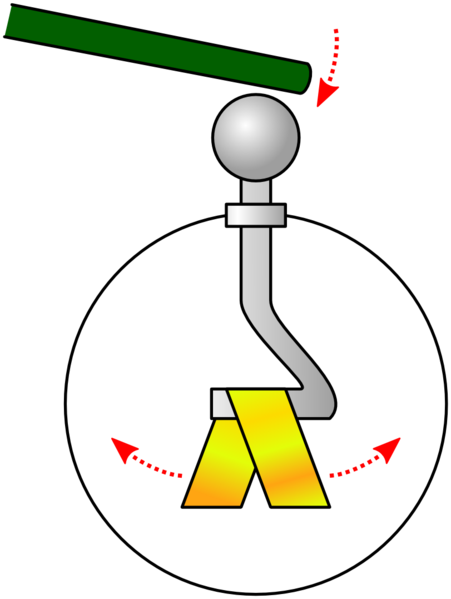
Placing charged rod above top plate without touching causes gold leaf to be repelled. Imbalance in charges of electroscope causes gold leaf to be repelled.
15.2.2 Induction
Induction charging of objects involves charged rod close to conductor(s) without contact, inducing redistribution of charges.
Charging 1 Conductor
Step 1. Charged rod placed close to conducting sphere. Unlike charges accumulate on side nearer to charged rod, like charges accumulate on other side.
Step 2. Touching sphere on right repels electrons further away from person’s body
Alt Step 2. Connect metal water tap to sphere with metal wire allowing electrons to flow to Earth. This is called earthing.
Step 3. Remove hand from sphere
Step 4. Remove charged rod.
15.2.3 Neutralising
Insulator Neutralising
Neutralise charged object by excess charge discharge.
Discharge insulators by heating or provision of humid conditions.
Conductor Neutralising
Neutralise charged object by excess charge discharge.
Discharge conductors by Earthing.
Earthing charged conductor provides path for excess electrons to flow away or electrons to flow in.
15.3 Examples of Electrostatic Charging
use of laser to create a path of ionised gas to facilitate and direct lightning towards ground harvesting stations.
Hazards Dry Bulk:
dry bulk friction against inner walls electrostatic charging hose & substance
Opposite charges between hose & substance cause sparking
If substance combustible, spark start fire or explosion
Hazards (transfer fluids)
Electrostatic charging & discharge in combustible substances presence danger prevented by careful grounding & earthing.
Air flow
Low humidity environment, moving vehicle acquire static charges as vehicle body & air create friction
Alight passengers touch vehicle outer metal body getting non-fatal, painful shock due to small electric discharge
Small discharge dangerous for trucks carrying volatile, flammable substances.
Danger reduced using tyres with carbon & embedded metal mesh dissipating charges to ground.
Airplane acquire static charges from friction with air, ice crystals, other air particles.
Static charge build up on plane only on outer metallic surface
Charges repel each other, furthest away from each other on outer most surface.
Airplane struck by lightning charges stay on outermost surface. People & equipment inside airplane unharmed by lightning
Charges on plan surface discharged to air via discharge rods
Mid-air refuelling between tanker aircraft & receiving aircraft, proper discharging of static charges important.
Spray Painting
Positively charged paint droplets repel each other while spray painting resulting in more uniform mist
Painted car part usually is metallic & grounded.
Approach of positive droplets to part to be painted attract free electrons in metal to attract to surface.
Attraction between paint & surface help droplets land on targeted part
Less wasted paint & more uniform resulting coat compared to uncharged paint.
Electrostatic charges may cause sparking
Electrostatic Precipitator
Incineration plants, power stations, chemical plants, factories produce waste gases with particulate pollutants in smoke dust, chemical droplet form.
Pharmaceutical facilities & hospitals may generate exhaust gases containing harmful bacteria & fungi that are removed effectively with an electrostatic precipitator before release into atmosphere.
Photocopiers
Photocopiers use static electricity to produce document copies.
Photocopier metal drum coated with selenium (photoconductor - only conduct electricity in light presence)
Drum surface charged positively by charged wire.
Original image place on clear glass sheet above drum, intense light beam shone onto image.
Image darker areas reflect less light, corresponding drum regions remain positively charged.
Drum regions corresponding to image lighter areas discharged by light beam.
Drum turns, positively charged image on drum attracts negatively charged toner powder.
Positively charged paper sheet passed over drum surface attracting negatively charged toner, paper image formed.
Paper heated & pressed fusing toner powder to paper permanently.
16. Electrical Current
16.1 Describing Energy Transfer by Electric Current in an Electric Circuit
1 ampere is electric current produced when 1 coulomb of charge passes through a point per second.
1 coulomb = amount of charge of 1 ampere current flow per second
1 coulomb approximately equal to charge of 6.25 x 10¹⁸ protons. Charge of each proton is about 1.60 x 10⁻¹⁹ C.
Electric current is rate of flow of electric charge.
I=QT where I= current (A)[ampere]{SI unit},
Q= charge (C)[coulomb]{derived unit},
t= time taken (s)[time]{SI unit}.
Conventional current is current flow as positive charges flow, assuming that positive charges flow from positive terminal to negative terminal of battery in closed circuit.
Electric circuit is closed path connected with metal wires with source (eg. battery), electrical component network (eg. light bulb).
Electron flow is flow of electrons from negative to positive terminal of battery, counterpart to conventional current.
Electric current measured with ammeter or digital multi-meter
Ammeter connected in series in electric circuit to measure electric current magnitude flowing in circuit.
Ideal ammeter has 0 resistance
16.1A Summary
Electric charge is electric charge flow rate, measured in ampere (A)
Electric current formula is I=QT
Positive charge flow is conventional current, electron movement in electrical circuit is electron flow.
16.1B
Volt is SI unit for electromotive force (e.m.f.) & potential difference (p.d.)
e.m.f. & p.d. are different despite both measured with volts.
Energy in battery chemical store transferred to electric charge kinetic store as it flows through circuit.
e.m.f. of electrical source is work done by source in driving unit charge around complete circuit.
E=WQ where E= e.m.f. of electrical source (V)
W= work done (J)
Q= amount of charge (C)
e.m.f. Is scalar quantity
Arrangement of electrical source determines amount of e.m.f. supplied to electrical components.
Electrical source can be arranged in either series or parallel.
Electrical source connected in series→add individual e.m.f. of each source.
Electrical source connected in parallel→highest e.m.f. Branch
Potential difference (p.d.) across circuit component is work done per unit charge in driving charges through component.
V=WQ where V= potential difference/voltage across component (V)
W= work done (J)
Q= amount of charge (C)
e.m.f. Is for electrical source, p.d. is for component
Electromotive Force (e.m.f.) | Potential Difference (p.d.) |
e.m.f. is work done to move each unit charge through circuit | p.d. Is work done by each unit charge passing through components |
e.m.f. is present even in open circuit | p.d. is 0 in absence of current |
Both e.m.f. & p.d. are measured by voltmeter or digital multi-meter in parallel with electrical source/component.
Positive terminal of electrical source must be connected to positive terminal of voltmeter.
Electrons flowing through circuit originate from circuit wire.
Battery supplies the energy that moves electrons.
Battery setups electric field in wires directing from positive to negative terminals of battery.
Flat battery is due to electrochemical reactions inside battery depleting materials producing electrochemical reactions.
16.2 Electrical Resistance Increases with Temperature
resistance = p.d./current
Electrical resistance slows down circuit electron flow.
Electrons flowing through component constantly collide with components’ ions & with other electrons. Such collisions oppose the flow of electrons.
Opposing force degree which electric current experiences flowing through component is component resistance.
Component resistance R is ratio of potential difference V across it to current I flowing through it.
R=V I where R= resistance of component ()
V= p.d. (V)
I= current (A)
Ohm’s Law states that current flowing through conductor between two points is directly proportional to potential difference across the two points provided temperature remains constant.
Resistor is conductor/insulator with high resistance, used in circuit to control current amount.
Fixed & Variable are 2 types of resistors.
Fixed resistor has fixed value & made of finely powdered carbon & ceramic mixture, held together by resin.
Ratio of mixture gives different resistor values. Values are marked with resistor colour bands.
Variety of resistor resistances ranging from few ohms to several million ohms.
Variable resistors can have different resistance values (Examples are rheostat & potentiometer)
Different resistance values can be set by moving slider along metal rod to change length of wire current flows through.
Object resistance dependent on shape & material
Longer cylinder, more collisions from electrons into particles.
Cylindrical resistor resistance R directly proportional to cylinder length l.
Larger cylinder cross-sectional area A increases electron flow number.
Cylindrical resistor resistance R inversely proportional to cylinder area A.
Relationship of material resistance & (length & cross-sectional area) is:
R=klA where k is constant
Constant is defined as substance resistivity dependent on material composition.
R=lA rearranged as =RlA
Resistivity is material resistance for unit area per unit length.
Resistivity is independent of material shape or size.
Resistivity is material intrinsic property
Resistivity SI unit is ohm metre (m)
Some materials resistivity
Material | Resistivity (m) |
silver | 1.6 x 10⁻⁸ |
copper | 1.7 x 10⁻⁸ |
tungsten | 5.5 x 10⁻⁸ |
iron | 9.8 x 10⁻⁸ |
constantan | 49 x 10-8 |
nichrome | 100 x 10-8 |
graphite | 3000 x 10-8 |
polythene | about 1016 |
Low resistivity materials are good electricity conductors. E.g.: Copper has low resistivity, often made into wires as electric current flows easily.
High resistivity materials are poor electricity conductors. Heat generation high, used for heating.
16.2.? Non-ohmic Conductors
Conductors without direct proportional relationship between V & I are non-ohmic conductors.
Non-ohmic conductor resistance vary with temperature. For tungsten, resistance increases with temperature increase.
16.2.? Object Resistance
Most metal resistance increase linearly with temperature.
Metal ions vibrate more vigorously about fixed positions @ higher temperatures, increasing collision number between free electrons & metallic ions, opposing or slowing down electron flow.
Equation R=VI can be rearranged into V=IR to form relationship between voltage & current.
Current amount I is directly proportional to potential difference V applied across material resistance R. Materials with such linear relationship is ohmic, @ constant temperature & physical conditions.
Non-ohmic conductors are without direct proportional relationship between V & I due to conductor resistance changing with temperature. E.g. are tungsten, diodes, negative temperature coefficient termistors.
Metallic non-ohmic conductor, temperature increases resistance.
Non-ohmic semi-conductor, temperature decreases resistance.
17. D.C. Circuits
17.1 Current, Potential Difference Resistance in Series Circuit
Common circuit symbols: switch, cell, battery, d.c. power supply, a.c. power supply, light bulb, potentiometer, light-dependent resistor, wires joined, wires crossed, fixed resistor, variable resistor (rheostat), fuse, wire coil, transformer, semiconductor diode, galvanometer, ammeter, voltmeter, 2 way switch, earth connector, light emitting diode, thermistor, bell.
Series circuit, components connected in 1 single loop.
Current at every point is identical.
Total potential difference supplied to circuit equals individual potential differences of resistor sum.
Effective resistance equals individual resistances sum.
In series circuit, V=V1+V2=IR1+IR2=I(R1+R2)
Hence, effective resistance is VI=(R1+R2), V=(R1+R2)
17.2 Current, Potential Difference Resistance in Parallel Circuit
Total current flowing in/out of parallel branches equal to sum of parallel branch individual currents.
Potential difference across parallel branches is the same.
Resistor effective resistance reciprocal equal to individual resistance reciprocal sum.
I=I1+I2=V1R1+V2R2=V(1R1+1R2), IV=1Re=1R1+1R2
Effective resistance is R1R2R1+R2.
17.3 Potential Dividers
Photoresister/Light-dependent resistor is electronic device convertinging non-electrical signal to electrical signal used in potential divider circuits.
Potential divider is voltage divider making use of voltage drop across resistors in series dividing voltage.
VS=IR1+IR2, I=1R1+R2VS, V1=IR1, hence V1=R1R1+R2VS, likewise, V2=R2R1+R2VS
Resistors replaced with potentiometer, continuous voltage ranges are obtained. Potentiometer is 3 terminal variable resistor. Third terminal connected to adjustable knob is adjusted to give any potential difference fraction across resistor ends.
Potentiometers maintain the same formula of potential differences
17.4 Transducers Usage in Potential Dividers
Transducer electronic divides convert physical condition changes into electrical signals to measure such physical conditions.
Transducers used in potential dividers to vary voltage output, allowing response to environmental changes.
Transducer examples are thermistors, light-dependent resistors (LDRs), photovoltaic cells & piezoelectric sensors.
Thermistors & LDRs are input transducers that convert non-electrical signals to electrical signals.
Thermistor resistance varies with temperature, aka thermally sensitive resistors.
2 types of thermistors: Negative temperature coefficient (NTC) thermistor where resistance decreases with increasing temperature, positive temperature coefficient (PTC) thermistor where resistance increases with increasing temperature.
Thermistors are very accurate & cost-effective at measuring temperature.
LDR resistance vary with light intensity.
Light intensity increasing reduces LDR resistance.
17.5 Annex
Diode only conducts when forward base (conventional current), no current flow when reverse-biased.
Semiconductor diode only allows unidirectional current flow.
18. Practical Electricity
Home appliance energy label encourages Singaporean consumers to use more energy efficient product, reducing electricity bills.
18.1 Electrical Heating & Measurement of Electricity Consumption
When using heating appliances, energy transferred electrically to internal stores of heating elements, usually long & thin nichrome/iron-chromium-aluminium alloy.
Electricity current passing through alloys rapidly increases temperature.
Heating elements have high electrical resistances opposing charge flow, free electrons bump into ions, fixed-position ions vibrate more vigorously vibrate, raising alloy temperature, energy in internal store increases.
Since V=WQ & Q=It, work done equation is:
W=VIt where W= work done (J)
V= p.d. of electrical component/heating element (V)
I= current flowing through component (A)
t= time (s)
Electricity consumption not stated on electrical appliances because dependent on usage, differs for diff. Household.
Instead, power rating given in W & V where V volts delivers power of W watts.
Since P=Wt,
P=VI where P= power (W)
V= p.d. of electrical component/heating element (V)
I= current flowing through component (A)
Since V=IR,
W=I2Rt & W=V2tR,
where W= work done (J)
I= current flowing through component (A)
R= resistance of component ()
t= time (s)
V= p.d. of electrical component/heating element (V)
P=I2R & P=V2R,
where P= power (W)
I= current flowing through component (A)
R= resistance of component ()
V= p.d. of electrical component/heating element (V)
Energy (Joules) & power (watts) are scalar quantities
Different appliances use different amounts of energy.
Recommended: Reduce usage of high electricity consumption appliances; Use low electricity consumption devices where possible.
Household has electricity metre measuring electricity consumption, measured in kilowatt hours (kW h)
1 kW h = 3.6 MJ = 3 600 000 J
1 kW h is energy used by 1 kW device in 1 hour
Electrical energy used (kWh) = Power (kW) x Time (h)
Electricity cost = rate x kWh
18.2 Using Electrical Components Safely
18.2.1 Electrical Hazards
Electrical hazards usually caused by damaged insulation, cable overheating, damp conditions, causing burns, electric shocks, fires.
Extra care needed to resolve electrical hazards to protect ourselves.
Human body can only withstand 50 mA current, larger current cause burns/damage to tissues/organs, may also cause involuntary contractions of muscles, resulting in death.
18.2.1.1 Damaged Insulation
Most common electrical fault. Caused by insulation damaged with age & prolonged use.
Aging insulation caused by stresses, high electric field & temperature. Aging insulators become brittle & break apart, exposing live conducting wires. Insulation may be damaged by rat gnawing. Touching exposed live wires cause electric shocks.
18.2.1.2 Cable Overheating
Electrical circuit rising temperatures.
Energy transferred electrically to device internal stores. E=I2Rt
Causes of overheating: current exceeds electrical cable limits; too many plugs connected to socket causing large current flow through wires; plug & socket contact is poor.
First 2 causes, too much current drawn leading to overloading. Since work done W=I2Rt, energy amount transferred to internal store rapidly increases with current.
Fires & explosions caused by overheating.
18.2.1.3 Damp Environment
Pure water does not conduct electricity. However, water usually contains impurities & charged ions that conduct electricity. Swimming pool activities cease with lightning strike possibility. Never use electrical appliances on wet surface or with wet hands.
Preventable by wearing rubber equipment during electrical repairs or electrical fault inspection.
Electrical shock occurs when electric circuit & ground contains person, rubber cut off path, ensuring safety
18.2.2 Electrcity Usage Safety Features
Fuses & circuit breakers prevent excess current.
Electrical appliances have earthed metal casing/double insulation preventing contact with live wires.
Safety device fuse prevents excessive current flow, containing fusible wire strip that melts when current flow exceeds a certain value, dependent on its rating. Typical household fuses are 1, 2, 3, 5, 10, 13 A. When fuse is broken, no current can pass through until it is replaced.
Circuit breaker are similar to fuses but are part of main electrical wiring. Circuit breakers also have current ratings. When current exceeds rating, circuit breaker trips, faulty appliance has to be removed before turning on circuit breaker.
Earth metal casing is metal enclosure of appliance electrical parts with almost no resistance, ensuring user safety during electrical fault by causing large live current to flow through earth metal casing to ground, causing circuit breaker to trip/fuse to blow.
Earth metal casings are expensive, instead double insulation is used with 2 layers of insulation enclosing all exposed metal work & live parts.
Three-pin/fuse plugs commonly used in singapore. Each pin is connected to earth, neutral & live respectively.
Earth wire is yellow & green needed to earth appliances with metal cases.
Neutral wire is blue & kept @ 0 voltage. Completes appliance electrical circuit current flow path.
Live wire usually brown, carrying high voltage & current.
Most of the time earth wires have no electric current, however dangerous when sudden electric surge causes current flow, hence must treat wire as if current flows through it.
Switches & safety features connected to live wire to break/complete circuit, also enabling such devices to cut off mains electricity supply.
Safety Feature | Electrical Hazard Prevention |
|---|---|
fuses | in socket plugs preventing excessive current |
circuit breaker | In distribution box preventing excessive current |
Earthed metal casing | Prevent live wire causing metal casing at high electrical potential |
double insulation | prevent contact with live wire |
earth wire | earth appliance metal casing |
19. Magnetism
19.1 Interactions Between Magnets & Magnetic Materials
19.1.1 Magentic Properties
Like poles repel, unlike poles attract.
Magnetic effects strongest at the poles.
Freely suspended magnet always rests in north-south direction relative the earth’s magnetic field. Example: Compass
Magnetic North & South Poles always occur together. Broken magnets will still have two poles.
Magnets attract magnetic materials (Iron, Nickel, Cobalt, Steel). Magnetic materials cannot repel.
Magnets are composed of atoms. At subatomic level electrons circulate around atomic nuclei & spin about own axes, creating an atomic magnet composed of subatomic dimensions.
There are regions called domains where atomic magnets align
Unmagnitised material have each domain in different orientations; net magnetic effect is 0. Magnetised material have each domain aligned in same direction.
Two bar magnets joined together is stronger than one bar magnet but weaker than two bar magnets separated.
19.1.2 Induced Magnetism
Proximity induced magnetism - magnetic material in contact/proximity to strong magnet or current-carrying solenoid may be magnetised.
Magnetised material can be magnetised by strong magnet stroking.
Magnetic field region is where magnetism force acts.
Magnetic field direction determined by right-hand grip (cockscrew) rule where thumb points to north pole and fingers show current direction.
19.1.3 Demagnetisation
Demagnetise magnet:
Place magnet in east-west direction (minimise effect of Earth magnetic field). Hit/Heat/Repeatedly drop magnet.
Place magnet in east-west direction inside solenoid with alternating current constantly changing direction. Reduce current to 0 or pull object out of solenoid.
External magnetic field & temperature variations reduce magnetism slowly.
Prevent demagnetisation:
Iron keepers to reduce stray magnetic fields, preserving magnetism.
19.1.4 Temporary & Permanent Magnets
Temporary magnets need electric current or permanent magnetic field to retain their magnetism. Permanent magnets do not.
“Soft”& “Hard” magnetic materials affect its ability to be magnitised & remain magnetised.
Magnetic Material | Soft | Hard |
Example | soft Iron | steel alloy |
Properties | easily magnetised & demagnetised | difficult to magnetise & demagnetise |
Common Uses | temporary magnets (junkyard electromagnets) | permanent magnets (hard disk drive magnetic recording media) |
Soft magnetic materials have stronger induced magnetism.
Iron, nickel, cobalt & rare-earth metals are magnetic metals. Most alloys of such metals are magnetic materials.
Most non-metals are non-magnetic.
19.1 Summary
Like poles repel, unlike poles attract.
Magnetic field strength strongest at poles.
Magnets rest in North-South direction.
Magnets have 2 poles, attract magnetic materials.
19.2 Showing Magnetic Field Around Magnet
Magnetic field lines are closely packed at magnet poles but are less dense & further away from magnet. They also connect opposite poles & exist inside magnet.
Magnetic field lines never cross, are continuous. Closer field lines mean stronger magnetic field.
Field lines always travel from north pole to south pole externally
Uniform magnetic fields are parallel & equally spaced, exerting constant magnetic force. Non-uniform magnetic fields are opposite of everything.
Field lines used to represent cross-pole interaction across magnets. Like pole field lines move away from each other. Unlike pole field lines go from north to south.
Neutral zone is where there is the weakest magnetic field.
Earth is a huge magnet, with south pole at magnetic north; magnetic north not geographic north, difference in angle is magnetic declination.
Magnetic field lines prioritise passing through magnetic materials.
20. Electromagnetism
20.1 Magnetic Effects of Currents
Ørsted Experiment: connect battery to resistor, to compass, to switch, back to battery. Observe battery when switch is closed & when current is reversed.
Electricity & Magnetism are linked.
Compass needles naturally point north-south. However in the presence of electric current, needles point in direction of magnetic field formed by electric curent. Reversing current reverses needle direction.
Magnetic field of wire is concentric circles formed using right-hand grip rule more spaced out further away from the wire showing diminishing force further away from wire. Closer circles mean stronger field.
The current magnetic field is temporary; this property is used to make temporary magnets.
Solenoid is long wire piece wound in coil. Current-carrying solenoid is electromagnet. Right-hand grip rule.
Solenoid magnetic field strength can be increased by: increasing current, increasing density of turns, placing soft iron core within.
Solenoids are used in circuit breakers.
20.2 Current in a Wire Causing the Wire to Move
Current magnetic field interacting with another magnetic field causes attraction or repulsion, resulting in motion if forces are large enough.
Fleming’s Left-Hand Rule: Thumb, Index Finger & Middle Finger all facing 90o away from each other with only middle finger bending. Thumb, Index Finger & Middle Finger correspond with force direction, Magnetic Field & Current respectively. If Magnetic Field is parallel to current no net force is created.
Explanation: Field lines of wire squeezes magnetic field lines in part where both are parallel, creating a denser magnetic field. This causes the wire to be pushed away from the stronger field to weaker field creating net force.
Moving charged particle beam will experience force in magnetic field. It will u-turn due to its motion due to net force.
21. Electromagnetic Induction
21.1 Electric Currents & Magnetic Fields Relation & Interaction
electromagnetic force + magnetic field => turning effect
turning effect + magnetic field => electromagnetic force
Moving magnet in and out of coil induces deflection on galvanometer connected to coil.
Changing magnetic field produces induced current.
Flux is density of magnetic field lines
Faraday’s Law of electromagnetic induction states that magnitude of induced e.m.f. in circuit directly proportional to magnetic flux rate of change in circuit.
Unchanging magnetic field induce no current.
Deflection observed from moving magnet regardless of direction.
E.m.f. increases the faster the magnet is moved in & out of solenoid.
Lenz’s Law states induced e.m.f. direction & closed circuit induced current magnetic effects oppose motion & change producing it.
Solenoid & Magnet repel each other.
Byproduct of law of conservation of energy.
Violation of this law would violate energy conservation law.
Increase magnitude of induced e.m.f.:
Speed of relative motion between coil & magnet increases.
Turns of coil increases.
Magnet strength increases.
Magnet dropped through thick copper tube induces current from the copper tube generating magnetic field. Induced current produces magnetic field opposing falling magnet direction slowing it down.
21.2 Current Produced from Movement
Moving magnet induces e.m.f. or current in nearby conductor.
Fleming’s right-hand rule has the thumb representing the conductor motion direction, the forefinger representing magnetic field direction, the middle finger representing the conventional current direction.
Fleming’s left-hand rule is for electric motors while Fleming’s right-hand rule is for generators.
Rectangular coil Mounted on Axle Rotating between 2 permanent magnets with magnetic field from left to right.
Continuous current flow induced in rectangular coil due to rotation.
Direction of current flow is always clockwise regardless of coil orientation; induced current changes direction each coil flip at half a rotation. Alternating induced e.m.f. creates alternating current.
Alternating current generator uses slip rings, ensuring rotating rectangular coil ends do not get twisted with each rotation. They also provice electric contact with brushed such that electric current flow continuously. Rotating coil through different positions creates a maximum to 0 to minimum transition of e.m.f.
E.m.f. induced amount depends on magnetic field lines cut by coil rate.
Output voltage will be doubled when doubling coil turn number.
Maximum output voltage will be doubled when doubling coil rotation frequency.
21.3 Current Generated in Alternating Form
Electric transformers.
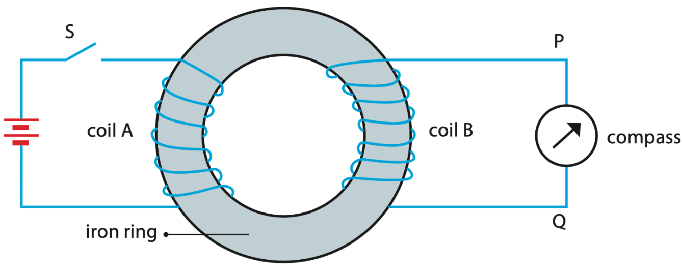
Compass needle deflects momentarily when circuit is open or closed then returns to resting position. This shows that there is current flowing in PQ that generates magnetic field.
Closing & opening of switch causes ring magnetic field to change. Magnetic field strength increases when current flows into coil A then decreases as current reduces to 0. Such changes induce coil B current causing compass needle deflection.
Closed switch induces current in coil B generating magnetic field opposing current increase in coil A as described by Lenz’s Law.
Opened switch induces current in coil B generating magnetic field opposing current decrease in coil A.
Compass of needle deflects in different directions.
Transformers are devices changing high alternating voltage to low alternating voltage & vice versa.
Singapore electricity supply transmitted at 400 kV which is then stepped down to 230 V for home usage.
Transformers has 2 coils of wire: Primary coil (connected to alternating current input) & Secondary coil (connected to load/output). Both coils wound around laminated soft iron core.
Laminated soft iron core reduces energy transfer to internal store by eddy currents. Lamination cuts eddy current path, keeping such induced currents small, reducing unwanted energy transfer (more efficient).
Soft iron is easily magnetised & demagnetised; they tend to concentrate magnetic field lines within itself improving primary & secondary coils link.
Changing magnetic field lines in primary coil links to secondary coil through soft iron core (changing magnetic flux), inducing secondary coil voltage & current. Voltage transferred from primary to secondary coil.
Relationship of primary & secondary coils:
VpVs=NpNs where Vs= secondary voltage (V);
Vp= primary voltage (V);
Ns= secondary coil turn number;
Np= primary coil turn number.
Step-up transformers have secondary voltage be greater than primary voltage. Vice versa for step-down transformers.
Laws of Conservation of Energy always applies even in transformers. Energy/Power transfer rate from primary to secondary coils have the following relationship:
VpIp=VsIs where Vs= secondary voltage (V);
Vp= primary voltage (V);
Ip= primary current (A);
Is= secondary current (A);
Relationship is only 100% true if no energy loss to unwanted energy transfer. Transformers where this is 100% true is an ideal transformer. Gets hit by reality
Useful output power will always be less than input power. Formula:
=output powerinput power100% where = efficiency
In ideal transformers, =1 or 100% .
21.3.2 Electricity Transmission & Distribution Issues & Solutions
Main challenge in electricity transmission & distribution is loss of power because of ohmic heating (P=I2R) in cables. Very large current transmission will create high losses due to power loss equation current squaring effect.
21.3.2.1 Thick Cables
Thick cables increase cross-sectional area to reduce resistance since cable length is fixed.
Disadvantages:
Thick cables increase cost, heavier, harder to suspend.
Low resistance still has high ohmic heating as it is proportional to current squared.
21.3.2.2 Reduce Transmitted Current
Reduces transmission cable ohmic heating.
Increase voltage substantially to maintain transmitted power.
Reducing current, power loss reduced since Ploss=I2R=(PoutV)2R since V is large.
Direct current produced by d.c. generators cannot be stepped up or down, causing high power loss during transmission. Hence current produced is always alternating form.