MAGNETISM AND MAGNETIC FORCES
1. Magnetic Fields
Poles of a Magnet
A magnet can exert a force on another nearby magnet. Magnets have two poles:
A north pole
A south pole
A magnetic force is strongest near a magnet’s poles.
The Rules of Magnetism
Two magnets will either attract or repel each other in the following way:
Like poles (N-N or S-S) repel
Unlike poles (N-S or S-N) attract
Magnetic forces are non-contact forces–this means that magnets affect each other without touching.
Induced and Permanent Magnetism
Iron, steel, nickel and cobalt are magnetic materials. They are affected by magnets and are attracted to either pole of a magnet.
Permanent Magnets
A permanent magnet is often made from a magnetic material such as iron. A permanent magnet always causes a force on other magnets, or on magnetic materials.
Key features of a permanent magnet:
It produces its own magnetic field
The magnetic field cannot be turned on and off – it is there all the time
Bar magnets and horseshoe magnets are examples of permanent magnets.
Induced Magnets
Unlike a permanent magnet, an induced magnet only becomes a magnet when it is placed in a magnetic field. The induced magnetism is quickly lost when the magnet is removed from the magnetic field.
The iron filings in the image become induced magnets when they are near the bar magnet. Like all induced magnets:
They are only attracted by other magnets, they are not repelled
They lose most or all of their magnetism when they are removed from the magnetic field
Testing for Magnetism
A permanent magnet can:
Attract or repel another permanent magnet
Attract a magnetic material (but not repel it)
This means that you can only show that an object is a permanent magnet by checking if it repels another magnet.
Magnetic Fields
A magnetic field is the region around a magnet where a force acts on another magnet or on a magnetic material.
Detecting Magnetic Fields
A magnetic field is invisible, but it can be detected using a magnetic compass. A compass contains a small bar magnet on a pivot so that it can rotate. The compass needle points in the direction of the Earth’s magnetic field, or the magnetic field of a magnet.
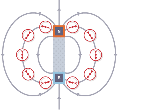
Magnetic fields can be mapped out using small plotting compasses:
Place the plotting compass near the magnet on a piece of paper
Mark the direction the compass needle points
Move the plotting compass to many different positions in the magnetic field, marking the needle direction each time
Join the points to show the field lines
The needle of a plotting compass points to the south pole of the magnet.
The behavior of a compass shows that the Earth has a magnetic field. Scientists believe that this field is produced by convection currents in the Earth’s core, which is made from iron and nickel. When a plotting compass is placed in the Earth’s magnetic field, the north pole of the compass will line up with the Earth’s magnetic field lines and point to magnetic south.
Drawing a Magnetic Field
The diagram shows the magnetic field around a bar magnet.
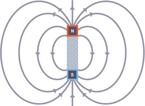
The diagram shows these key features:
The magnetic field lines never cross each other
The closer the lines, the stronger the magnetic field
The lines have arrowheads to show the direction of the force exerted by a magnetic north pole
The arrowheads point from the north pole of the magnet to its south pole
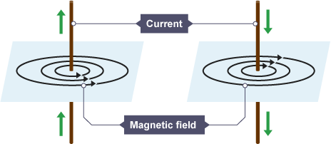
Magnetic Fields in a Wire
When a current flows in a wire, it creates a circular magnetic field around the wire. This magnetic field can deflect the needle of a magnetic compass. The strength of the magnetic field is greater:
Closer to the wire
If the current is increased
Solenoids
A solenoid consists of a wire coiled up into a spiral shape. When an electric current flows, the shape of the magnetic field is very similar to the field of a bar magnet. The field inside a solenoid is strong and uniform. The small magnetic fields caused by the current in each coil add together to make a stronger overall magnetic field.
2. Uses of Magnetism
The Motor Effect
A wire carrying a current creates a magnetic field. This can interact with another magnetic field, causing a force that pushes the wire at right angles. This is called the motor effect.
The current is traveling along the wire and the magnetic field from the permanent magnet goes from left to right. The field from the permanent magnet and the field due to the current in the wire combine and there is a force on the wire. The current, the magnetic field and the force are all at right angles to one another.
If the current and the magnetic field are parallel to each other (i.e. they are in the same direction) they cancel each other out, and no force is generated. This is because the wire is not passing through any magnetic field lines.
Fleming’s Left-hand Rule
The force on a given length of wire in a magnetic field increases when:
The current in the wire increases
The strength of the magnetic field increases
For any given combination of current and magnetic field strength, the force is greatest when the direction of the current is 90° to the direction of the magnetic field. There is no motor effect force if the current and magnetic field are parallel to each other.
The direction of the force can be found using Fleming’s left-hand rule.
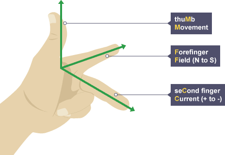
Hold your thumb, forefinger and second finger at right angles to each other:
The thumb shows the direction of the motor effect force on the conductor carrying the current
The forefinger is lined up with magnetic field lines pointing from north to south
The second finger is lined up with the current pointing from positive to negative
Calculating Electric Force
To calculate the force on a wire carrying a current at right angles to a magnetic field, use the equation:
Force on a conductor (at right angles to a magnetic field) carrying a current = magnetic flux density × current × length
This is when:
Force is measured in newtons (N)
Magnetic flux density (magnetic field strength) is measured in tesla (T)
Current is measured in amps (A)
Length is measured in meters (m)
Example:
2 A flows through a 50 cm wire. Calculate the force acting on the wire when it is placed at right angles in a 0.4 T magnetic field.
First convert the units:
50 cm = 50 ÷ 100 = 0.5 m
Then substitute the values into the equation:
force on a conductor carrying a current = magnetic flux density × current × length
force = 0.4 × 2 × 0.5
force = 0.4 N
Electric Motors
A coil of wire carrying a current in a magnetic field experiences a force that tends to make it rotate. This effect can be used to make an electric motor.
The diagram shows a simple motor using direct current (dc).
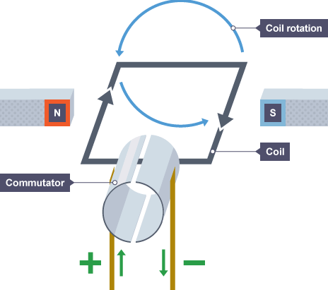
Starting from the position shown in the diagram of the dc motor:
Current in the left hand part of the coil causes a downward force, and current in the right hand part of the coil causes an upward force
The coil rotates anti-clockwise because of the forces described above
When the coil is vertical, it moves parallel to the magnetic field, producing no force. This would tend to make the motor come to a stop, but two features allow the coil to continue rotating:
The momentum of the motor carries it on round a little
A split ring commutator changes the current direction every half turn
Once the conducting brushes reconnect with the commutator after a half turn:
Current flows in the opposite direction through the wire in the coil
Each side of the coil is now near the opposite magnetic pole
This means that the motor effect forces continue to cause anti-clockwise rotation of the coil.
Loudspeakers
The motor effect is used in loudspeakers. In these devices, variations in an electric current cause variations in the magnetic field produced by an electromagnet. This causes a cone to move, which creates pressure variations in the air and forms sound waves.
Alternating current (ac) supplied to the loudspeaker creates sound waves in the following way:
A current in the coil creates an electromagnetic field
The electromagnetic field interacts with the permanent magnet, generating a force which pushes the cone outwards
The current is made to flow in the opposite direction
The direction of the electromagnetic field reverses
The force on the cone now pulls it back in
Repeatedly alternating the current direction makes the cone vibrate in and out
The cone vibrations cause pressure variations in the air, which are sound waves
To make a loudspeaker cone vibrate correctly, the electric current must vary in the same way as the desired sound. Headphones contain small loudspeakers.
3. Electromagnetic Induction
Potential Difference
A potential difference or voltage is needed to make an electric current flow in a circuit.
Inducing a Potential Difference
A potential difference can be induced (created) in a conductor when there is movement between the conductor and a magnetic field. This can occur in two different ways:
a coil of wire is moved in a magnetic field
a magnet is moved into a coil of wire
This is called electromagnetic induction and is often referred to as the generator effect.
The induced voltage produces an induced current if the conductor is connected in a complete circuit. As with all currents, the induced current creates a magnetic field around itself.
It is important to remember that if a magnet is moved into a coil of wire, the induced magnetic field tends to repel the magnet back out of the coil. This effect occurs whether a magnet is moved into a coil, or a coil is moved around a magnet.
Factors Affecting the Induced Potential
The direction of the induced potential difference or induced current depends on the direction of movement. The current is reversed when:
The magnet is moved out of the coil
The other pole of the magnet is moved into the coil
An induced potential difference or induced current will increase if:
The speed of movement is increased
The magnetic field strength is increased
The number of turns on the coil is increased
Alternators
An alternating current (ac) generator is a device that produces a potential difference. A simple AC generator consists of a coil of wire rotating in a magnetic field. Cars use a type of AC generator, called an alternator, to keep the battery charged and to run the electrical system while the engine is working.
As one side of the coil moves up through the magnetic field, a potential difference is induced (created) in one direction. As the rotation continues and that side of the coil moves down, the induced potential difference reverses direction. This means that the alternator produces a current that is constantly changing. This is alternating current or ac.
Alternator Output on a Graph
The output of an alternator can be represented on a potential difference–time graph with potential difference on the vertical axis and time on the horizontal axis.
The maximum potential difference or current can be increased by:
Increasing the rate of rotation
Increasing the strength of the magnetic field
Increasing the number of turns on the coil
Dynamos
A direct current (dc) generator is another device that produces a potential difference. A simple dc generator consists of a coil of wire rotating in a magnetic field. However, it uses a split ring commutator rather than the two slip rings found in alternating current (ac) generators. Some bike lights use a type of dc generator called a dynamo to run the lamps while the wheels are turning.
In a dynamo, a split ring commutator changes the coil connections every half turn. As the induced potential difference is about to change direction, the connections are reversed. This means that the current to the external circuit always flows in the same direction.
Dynamo Output on a Graph
The output of a dynamo can be shown on a potential difference–time graph. The graph shows a sine curve that stays in the same direction all the time. The maximum potential difference or current can be increased by:
Increasing the rate of rotation
Increasing the strength of the magnetic field
Increasing the number of turns on the coil
Microphones
The microphone is a device that converts sound waves into electrical signals. Microphones use the generator effect to induce (create) a changing current from the pressure variations of sound waves.
Moving-coil Microphones
In a moving-coil microphone:
Pressure variations in sound waves cause the flexible diaphragm to vibrate
The vibrations of the diaphragm cause vibrations in the coil
The coil moves relative to a permanent magnet, so a potential difference is induced in the coil
The coil is part of a complete circuit, so the induced potential difference causes a current to flow around the circuit
The changing size and direction of the induced current matches the vibrations of the coil
The electrical signals generated match the pressure variations in the sound waves
4. Transformers
What is a Transformer?
A transformer is a device that can change the potential difference or voltage of an alternating current (ac):
A step-up transformer increases the potential difference
A step-down transformer reduces the potential difference
Structure of a Transformer
A basic transformer is made from two coils of wire; a primary coil from the ac input and a secondary coil leading to the ac output. The coils are not electrically connected. Instead, they are wound around an iron core. This is easily magnetized and can carry magnetic fields from the primary coil to the secondary coil.
When a transformer is working:
A primary potential difference drives an alternating current through the primary coil
The primary coil current produces a magnetic field, which changes as the current changes
The iron core increases the strength of the magnetic field
The changing magnetic field induces a changing potential difference (voltage) in the secondary coil
The induced potential difference produces an alternating current in the external circuit
Potential Difference
The ratio of potential differences on the transformer coils matches the ratio of the numbers of turns on the coils.
This equation can be used to calculate what the output might be from a particular transformer, or to work out how to design a transformer to make a particular potential difference (pd) change:
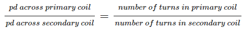
This is when:
The potential difference in the primary (input) coil is in volts (V)
The potential difference in the secondary (output) coil is in volts (V)
In a step-up transformer, the potential difference in the secondary coil is greater than the potential difference in the primary coil. In a step-down transformer, the potential difference in the primary coil is greater than the potential difference in the secondary coil.