Polarography Basic Analysis
Polarography Basic Analysis
Basic Analysis Process
Polarography involves applying a linearly decreasing voltage to an electrochemical cell.
The resultant current flowing through the cell is continuously recorded.
A plot of current versus the potential of the mercury electrode is generated, known as a polarogram.
Interpretation of Results
A step change in current is indicative of the electrolysis occurring with the analyte, also referred to as a polarographic wave.
The position of the step change correlates with the identity of the analyte, while the magnitude of the step change corresponds to its concentration.
The diffusion limited current can be determined from the equation: .
Calibration Process
The polarograph must undergo calibration for accurate quantitative analysis. This involves:
Taking readings of a series of standards with known concentrations.
Plotting a calibration graph for comparisons.
Utilizing the graph to determine the concentration of an unknown analyte.
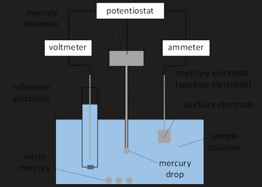
Polarograph Setup
Mercury Electrode Setup
The mercury electrode comprises a reservoir of mercury connected to a fine capillary.
Mercury flows through the capillary, forming a drop that is subsequently released.
Regular intervals are maintained for taking readings.
Mercury Electrode Operation
At the electrode's surface, the analyte undergoes electrolysis.
Reduced species can potentially poison the electrode, necessitating continuous renewal and growth of the surface.
The release of drops stirs the solution, effectively removing the electrolysis products from the vicinity.
Advantages of Mercury Electrode
Provides a hydrodynamic environment due to constant exposure to fresh solution.
Benefits include:
Chemical inertness.
High potential needed for hydrogen evolution.
Easy cleaning properties.
Excellent electrical conduction.
Electrochemical Cell Components
Auxiliary Electrode
The auxiliary electrode enables the passage of electricity through the cell.
Often consists of a platinum sheet, prized for its large surface area and low resistance.
Reference Electrode
Necessary for measuring and regulating the mercury electrode's potential.
Must avoid electrolysis within this reference electrode to ensure accurate readings.
A high resistance voltmeter provides a “zero current” reference under equilibrium conditions.
Electrolysis Overview
Electrolysis Setup
Involves the following processes:
Cathode Reaction: Cations gain electrons and become neutral; for metal ions, .
Anode Reaction: Anions lose electrons leading to a neutral species, often gaseous; e.g., .
Current in Electrolysis
A significant rise in current occurs when the cell voltage surpasses the decomposition voltage of the ions being electrolyzed.
Electrode Dynamics
Processes of Electrode Dynamics
Transport of cations from the bulk solution to the cathode surface.
Electrochemical conversion of cations to neutral species.
Current Dynamics
Current (i) is defined as: , where:
z = number of electrons transferred in the reaction
A = area of the electrode
F = Faraday constant
j = rate of the limiting process.
Rate of Electrochemical Conversion
The rate of electrochemical conversion (jR) is influenced by the overpotential: jR=[M+]S⋅k0⋅e−RTαzFη where:
: concentration of cations at the electrode surface
: standard rate constant
: overpotential
: transfer coefficient (typically ).
Overpotential and Current Relationship
The overpotential is defined as:
Current exhibits exponential rise in response to overpotential and eventually reaches a point where cations are instantaneously electrolyzed at the electrode surface, leading to dominance by mass transport.
Mass Transport Mechanisms
Modes of Ion Transport
Ions can reach the electrode surface via:
Convection: Movement due to stirring of the solution.
Migration: Movement due to electric field forces.
Diffusion: Movement along concentration gradients.
Fick's Law of Diffusion
Diffusion rate is based on the concentration variance from the surface to the bulk: jD = D([M+]B−[M+]S) / δ where:
= rate of mass transport
= diffusion coefficient of the cation
= bulk cation concentration
= surface cation concentration
= thickness of the diffusion layer (which is constant for a specific setup).
Current Under Limitations
For mass transport limited processes, surface concentration becomes negligible, leading to the expression:
jD= D([M+]B−[M+]S) / δTherefore, the diffusion limited current iD iD = zAF⋅M+]B/ δ
All terms remain constant except , clustering the current magnitude with bulk concentration and thus establishing a direct relationship between the current and the concentration gradient.
Practical Considerations in Polarography
Purge Gas Importance
Dissolved oxygen in the solution can interfere by being electrolyzed during experiments.
Utilizing nitrogen purges eliminates oxygen interference in readings.
Background Electrolyte Requirements
Minimizes migration impacts and maintains neutrality in ions:
Should be chemically/electrochemically inert (0.1 M or above).
100 times the analyte concentration is recommended to prevent migration interference.
Low conductivity samples may limit currents due to resistance (Ohm's Law: ).
Ionic Strength Stabilization
Background electrolytes also help uphold consistent ionic strength, thus maintaining reaction rates and coefficients.
Current Maximum Suppressors
To eliminate current maxima, a current maximum suppressor (depolarizer) is added, typically a surfactant (e.g. Triton X-100) at or below 0.002 M concentration.
Polarography Errors
Mass Transport Disturbances
Results can be skewed due to variations in mass transport, leading to peak currents overlaying standard step changes.
Two types of maxima: first kind and second kind, both caused by increased rates of mass transport at the electrode surface.
Pulse Techniques in Polarography
Importance of Pulse Techniques
Enhance the ratio between faradaic and charging currents:
Faradaic current: Results from electrolysis.
Charging current: Related to the electrical double layer at the electrode surface.
The goal is to maximize faradaic while minimizing charging current to improve sensitivity.
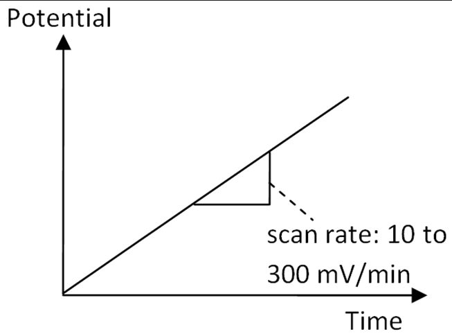
Linear Sweep Technique
The standard experiment without pulses is deemed a linear sweep.
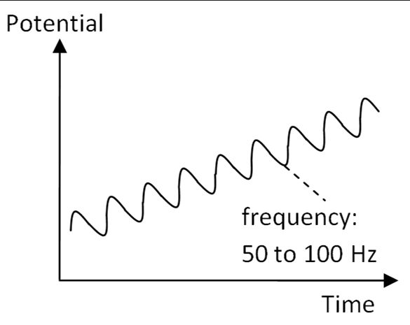
AC Techniques Overview
AC Techniques Description
AC techniques involve an oscillating potential superimposed on a linear slope, helping to enhance data quality.
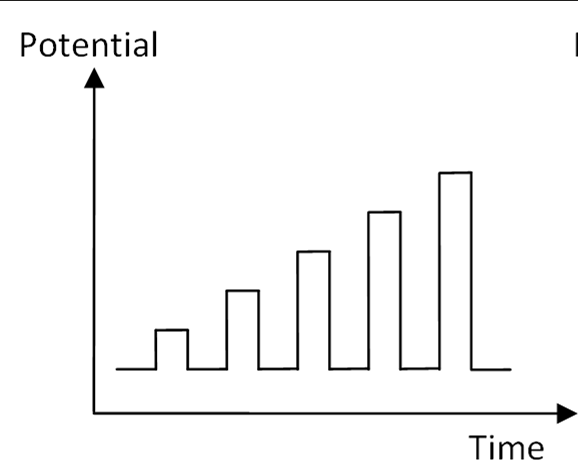
Normal Pulse Techniques
Implementing successive pulses with increasing amplitude into the procedure.
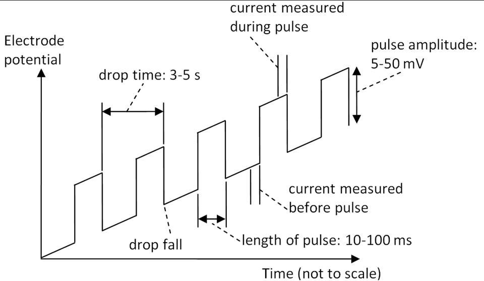
Differential Pulse Techniques
Utilizing pulses that vary in amplitude and duration, allowing for improved resolution and sensitivity in analytical measurements. These techniques enhance the detection of trace levels of substances and can be particularly beneficial in complex matrices.
Application in Polarography
Particularly valuable for improving sensitivity in measurements.
Fixed magnitude pulses are added atop a linear ramp, applied right before the mercury drop detaches.
Current is recorded immediately before and during the pulse, synchronizing data acquisition with drop size maxima:
The current is registered at the pulse end to record faradaic current at maximum and minimize charging current.
The technique can detections as low as compared to using the linear sweep method.