Electrons and Spectra
🧪 Electron Cloud Structure
Electron Behavior in Atoms
Electrons move very fast, spin, are repelled by each other, and are attracted to the positively-charged nucleus. The electron cloud is very large compared with the tiny nucleus, practically weightless, and takes up significant space despite electrons being very small.
Energy Levels and Shells
Electron clouds contain shells (also called energy levels or n numbers) arranged in rings:
Shell | Maximum Electrons |
|---|---|
1st | 2 |
2nd | 8 |
3rd | 18 |
4th | 32 |
5th | 32 |
Key Principle: Electrons fill shells closest to the nucleus first, with outer shells filled last due to attraction to the nucleus.
⚛ Subshells and Orbitals
Four Subshell Types
The periodic table is organized into 4 distinct sections based on electron cloud shapes:
s subshell: holds 2 electrons (1 orbital)
p subshell: holds 6 electrons (3 orbitals)
d subshell: holds 10 electrons (5 orbitals)
f subshell: holds 14 electrons (7 orbitals)
Orbital Structure
Each orbital holds 2 electrons spinning in opposite directions. Subshells are composed of orbitals, with the number of orbitals determining maximum electron capacity.
📝 Writing Electron Configurations
Configuration Rules
Start with lowest energy first (1s)
Follow the 4 sections of the periodic table
Electrons in each section should add up to total
Recognize overlap between s and d blocks
Stop on the target element
Configuration Format
The notation follows: subshell where:
= energy level/row
subshell = s, p, d, or f
= number of electrons
for subshell d, n = n - 1, and for f n = n - 2
Practice Examples
Fluorine (F):
Atomic number 9 = 9 electrons
2 electrons in 1st shell, 7 in 2nd shell
Boron (B):
Argon (Ar):
Copper (Cu):
Tellurium (Te):
🎯 Key Patterns
Periodic Table Organization
s-block: Groups 1-2
p-block: Groups 13-18
d-block: Transition metals
f-block: Lanthanides and actinides
Energy Level Overlap
As energy levels increase, sublevels branch and create points of overlap, particularly between s and d orbitals, affecting electron filling order in transition metals.
🎯 Learning Objectives
Today's outcome: Analyze the locations of electrons and relate to the Periodic Table and valence electrons.
Standard: HS-PS1-1 - Use the Periodic Table as a model to predict the relative properties of elements based on the patterns of electrons in the energy levels of an atom.
⚛ Atomic Structure Overview
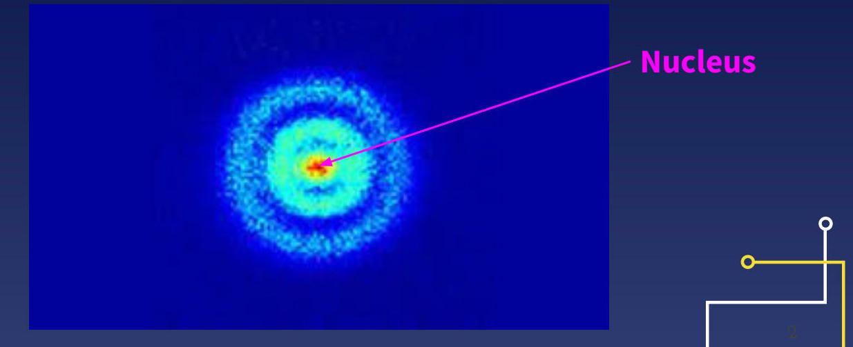
The nucleus (highlighted in pink) contains protons and neutrons, while electrons occupy specific regions called electron clouds around the nucleus.
🔬 Electron Behavior in the Electron Cloud
Electrons in the electron cloud exhibit several key behaviors:
Move at very high speeds
Spin while moving
Experience repulsion from other electrons
Are attracted to the positively-charged nucleus
🏗 Electron Cloud Organization
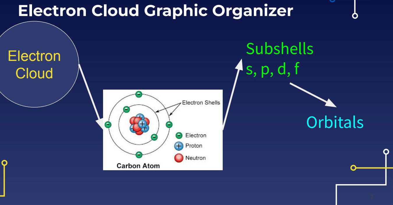
Carbon Atom Example
6 protons (blue)
6 neutrons (red)
6 electrons (green)
Electron Shells
Inner shell: 2 electrons
Outer shell: 4 electrons
Subshell Types
s subshell
p subshell
d subshell
f subshell
🎆 Real-World Connection: Fireworks and Electrons
The colors in fireworks result from electrons in different elements absorbing energy and jumping to higher energy levels, then releasing that energy as light when they return to lower levels.
🌟 The Electron Cloud Model
The electron cloud represents the probability distribution of electrons around the nucleus. This model shows that electrons don't orbit in fixed paths but exist in regions of space called orbitals.
Key components of atomic structure:
Electron shells - main energy levels (represented by numbers 1, 2, 3...)
Subshells - subdivisions within shells (s, p, d, f)
Orbitals - specific regions where electrons are likely found
Electron Configuration Principle: Electrons fill orbitals starting from the lowest energy level first, following the Aufbau principle.
📊 Periodic Table Blocks
The periodic table is organized into four distinct blocks based on electron configurations:
Block | Color | Subshell | Electron Capacity |
|---|---|---|---|
s-block | Pink | s orbitals | 2 electrons |
p-block | Yellow | p orbitals | 6 electrons |
d-block | Blue | d orbitals | 10 electrons |
f-block | Green | f orbitals | 14 electrons |
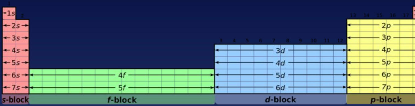
This diagram illustrates how the periodic table's structure directly relates to electron configurations, with each block representing different subshell types.
🔄 Writing Electron Configurations
The standard method for writing electron configurations follows these principles:
Start with 1s (lowest energy)
Move through subshells in order of increasing energy
Follow the diagonal rule (follow arrows on configuration diagrams)
Account for overlap between s and d orbitals
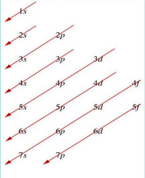
This visual guide shows the correct order for filling electron orbitals, following the red arrows from 1s → 2s → 2p → 3s and so on.
📝 Example Configurations
Fluorine (Atomic number 9):
Iron (Fe):
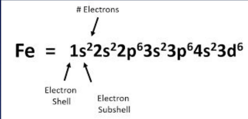
The diagram breaks down iron's configuration, showing how electrons distribute across different energy levels and subshells.
⚡ Shortcut Method Using Noble Gases
For longer configurations, use noble gas notation:
Standard: Arsenic (As) -
Shortcut:
Noble Gas Rule: Use the symbol of the noble gas (Group 18) that precedes your element in brackets, then add remaining electrons.
🧮 Orbital Capacities
Each subshell type has specific orbital and electron capacities:
Subshell | Orbitals | Max Electrons | Total Capacity |
|---|---|---|---|
s | 1 orbital | 2 electrons | 2 electrons |
p | 3 orbitals | 2 electrons each | 6 electrons |
d | 5 orbitals | 2 electrons each | 10 electrons |
f | 7 orbitals | 2 electrons each | 14 electrons |
📈 Orbital Diagrams
Orbital diagrams use arrows to represent electrons in individual orbitals:
Lines represent individual orbitals
Up/down arrows show electron spin (opposite spins pair up)
Sodium example:
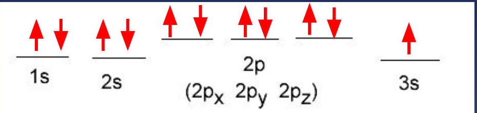
This diagram clearly shows how electrons fill orbitals, with paired electrons having opposite spins (arrows pointing in opposite directions).
🎯 Key Principles
Pauli Exclusion Principle: Each orbital holds maximum 2 electrons with opposite spins
Hund's Rule: Electrons fill degenerate orbitals singly before pairing
Aufbau Principle: Electrons occupy lowest energy orbitals first## 📝 Orbital Diagrams and Electron Configuration
Key Rule for Orbital Diagrams
When writing orbital diagrams, we follow all the same rules for configurations but we add one: When there is more than one orbital in a sublevel, make sure each orbital has one electron before doubling up.
Nitrogen Example
The orbital diagram for nitrogen shows:
1s²: 2 electrons (paired)
2s²: 2 electrons (paired)
2p³: 3 electrons (unpaired in separate orbitals)
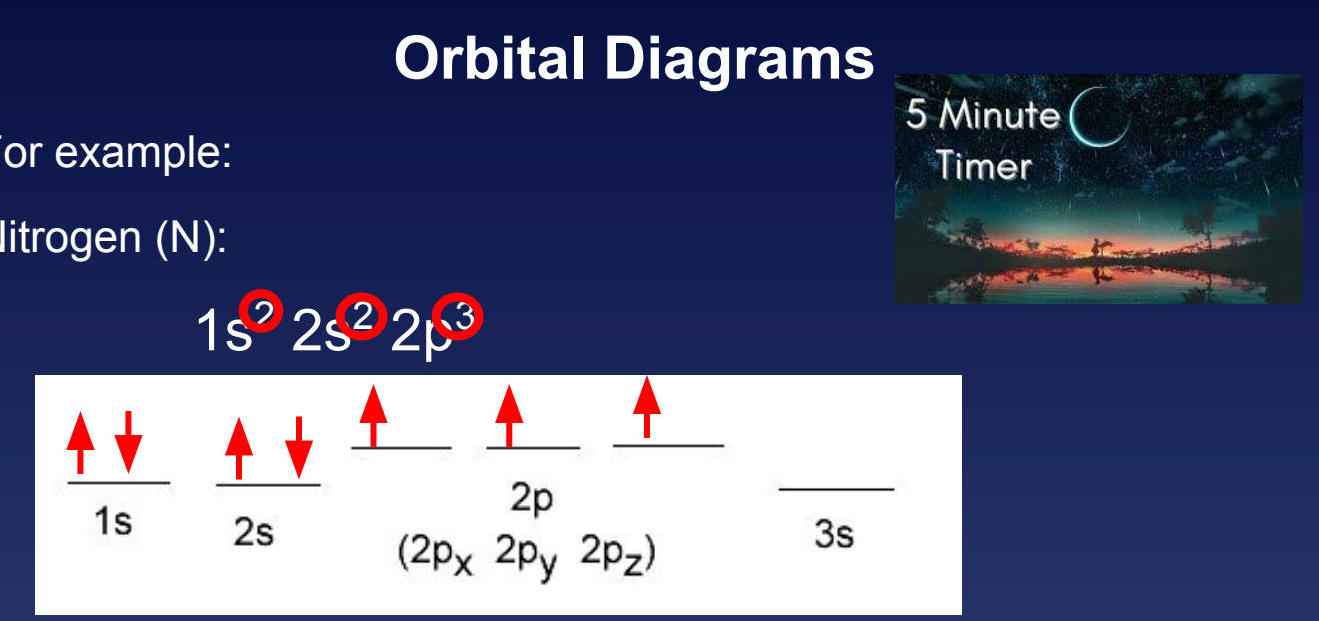
Important Note: For nitrogen, we did NOT put an up and down arrow in the 2pₓ. Instead, we made sure that each of the 2pₓ, 2pᵧ, and 2p₂ orbitals had one electron before doubling up.
⚡ Energy Shell Diagrams
Energy shell diagrams show the total number of electrons in a given energy level (n) regardless of the sublevel.
Vanadium (V) Example:
Atomic number: 23
Electron configuration:
2 electrons in the 1st energy level
Energy "shell" corresponds to n value
🔬 Valence Electrons
Valence electrons are the outermost electrons (those in the highest energy shell). These are the electrons involved in chemical bonding.
🎯 Lewis Dot Structures
Lewis dot structures visually represent:
Valence electrons as dots around the element symbol
Covalent bonds as shared electron pairs
Lone pairs as non-bonding electron pairs
📊 Noble Gas Configurations and Electron Dot Structures
The table below shows period 3 elements with their noble gas configurations and electron dot structures:
Key observations:
Sodium (Na) has 1 valence electron (highlighted in red)
Elements are organized by group numbers 1-18
Each element shows:
Noble gas configuration
Number of valence electrons
Electron dot structure
Valence Electrons 🧪
Valence electrons are electrons in the outermost energy level of an atom. These electrons determine an element's chemical properties and reactivity.
Alkali Metals Configuration
The electron configurations for the first 3 alkali metals show a clear pattern:
Element | Electron Configuration | Valence Electrons |
|---|---|---|
Sodium | 1 | |
Potassium | 1 |
Key Pattern: Each element in the column has the same configuration ending except for the energy level (n). This is the valence shell – the outermost or highest energy level.
Halogens Configuration
The halogens demonstrate the same pattern with 7 valence electrons:
Element | Electron Configuration | Valence Electrons |
|---|---|---|
Fluorine | 7 | |
Chlorine | 7 | |
Bromine | 7 | |
Iodine | 7 |
Important: When counting valence electrons, only count the ones in the highest energy level.
Lewis Dot Diagrams ⚛
Lewis dot diagrams are a notation using chemical symbols and dots to represent valence electrons, named after scientist Lewis who first used this notation.
Key Principles:
Electrons are negative and repel one another, so space them apart
Electrons tend to be in pairs as they spin in opposite directions
Drawing Lewis Dot Diagrams for Oxygen
Step-by-step process:
Determine electron configuration: (6 valence electrons)
Use element symbol: O
Pretend there's a "box" around the symbol
Place electron "dots" one at a time around the box
Account for all valence electrons with no more than 2 on any given side
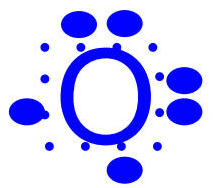
The final diagram shows all 6 valence electrons properly distributed around the oxygen symbol.
Atomic Energy States ⚡
Key Vocabulary:
Ground state: Lowest possible energy for all electrons (AKA - the electron configurations as we've written them)
Excited state: Electrons temporarily in a higher energy state
Quantum leap: Electrons jumping from one energy level to another either by absorbing energy or releasing energy in the process
Electromagnetic Radiation 📡
The electromagnetic spectrum encompasses all types of electromagnetic radiation, from gamma rays to radio waves.
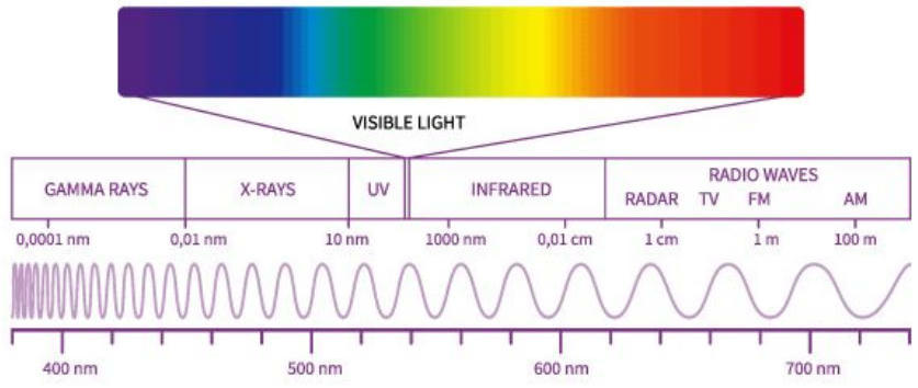
Key Relationship:
The difference between gamma rays (deadly to humans) and radio waves (which pass through us 24/7 as we use them for TV, Radio, Cell phones, etc.) is the wavelength, which relates to energy.
Bohr Model Applications 🌟
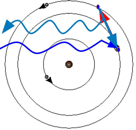
Energy Absorption and Release:
Energy is absorbed by an electron
As energy is absorbed, the electron is pushed into an "excited" state
Atoms are not stable in excited states and will return to ground state
When returning to ground state, energy is released (Law of Conservation)
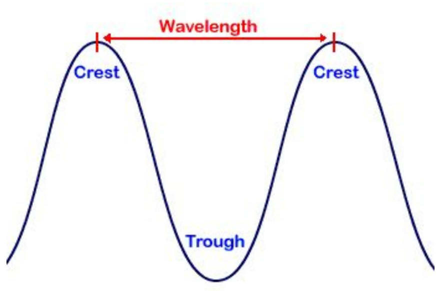
Wave Equations and Electron Transitions 🌊
Fundamental Wave Equation:
or
Where:
= speed of light = m/s
(lambda) = wavelength (measured in m)
(nu) = frequency (Hz or s⁻¹)
Electron Transition Series:
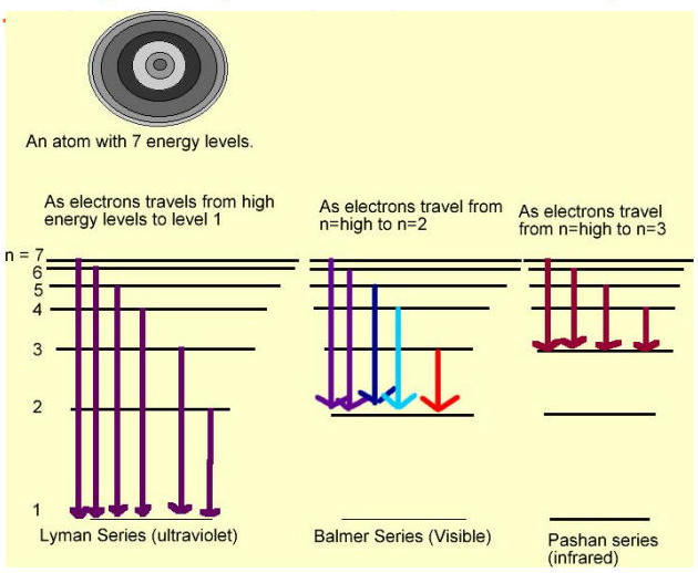
Series Name | Transition To | Radiation Type | Color |
|---|---|---|---|
Lyman Series | Level 1 | Ultraviolet | Purple |
Balmer Series | Level 2 | Visible | Blue/Red |
Pashan Series | Level 3 | Infrared | Red |
These "series" are named for the scientists who first discovered the relationship between electrons and wavelength.