BASIC PRINCIPLES OF DIGITAL RADIOGRAPHY
WHAT IS DIGITAL RADIOGRAPHY?
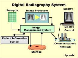
It is any image acquisition process that produces an electronic image that can be viewed and manipulated on a computer.
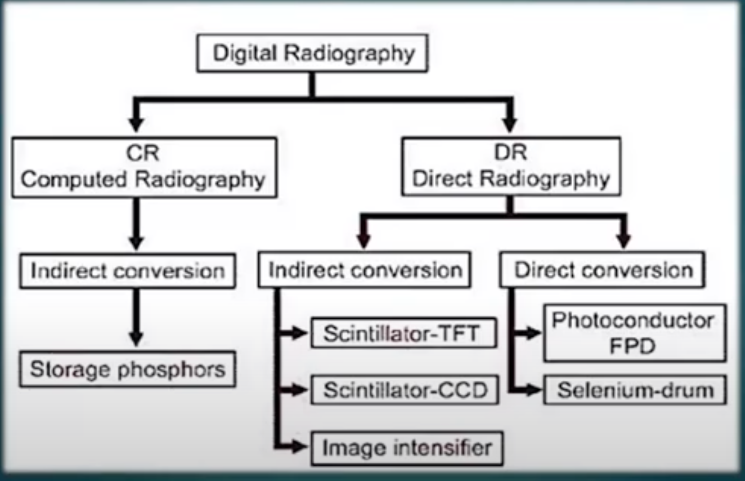
DR uses flat panel detectors based on direct or indirect conversion of x-rays to charge, which is then processed to produce digital image
The x-ray exposure is directly converted into pixels as digital data into the computer memory with the use of an imaging plate.
ADVANTAGES OF DIRECT/DIGITAL RADIOGRAPHY
The use of DR is associated with lower patient exposures because of low imaging failure rates
The high speed of image acquisition is another advantage of DR technology
Image quality is excellent with DR whereas CR images are somewhat inferior
DR systems provide high speed workflow
DISADVANTAGES OF DIRECT/DIGITAL RADIOGRAPHY
DR systems are not very flexible for taking difficult views
Initial investment costs are very high, averaging 5 times that of CR setup including the reader and PSPs.
DIGITAL IMAGE CHARACTERISTICS
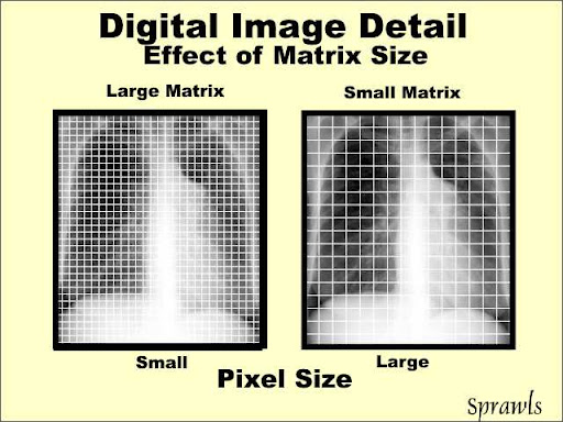
A digital image is a matrix of picture elements or pixels.
A matrix is a box of cells with numeric value arranged in rows and columns.
The numeric value represents the level of brightness or intensity at that location in the
image.An image is formed by a matrix of pixels. The size of the matrix is described by the
number of pixels in the rows and columns.
PICTURE ELEMENT OR PIXELS
Each pixel in the matrix is capable of representing a wide range of shades of gray from white to black.
It is the basic unit of a digital image
Pixel Size = Field of view ( ) FOV /matrix size
Measured in x and y direction
Each pixel contains a specific value, the value contained in each pixel represents the part of a
certain anatomy of the part being imaged.

Pixel Density
It refers to the number of pixels present on a digital image
Increasing pixel density would increase the resolution of our digital image
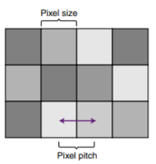
Pixel Pitch
It is the distance between center of one pixel and the center of an adjacent pixel.
Pixel Pitch Determines the pixel density of the digital image
Rationale: Decreasing pixel pitch would increase pixel density. Increasing pixel pitch would decrease pixel density.
Relationship: Increasing the pixel density and decreasing the pixel pitch increases spatial resolution. Decreasing pixel density and increasing pixel pitch decreases spatial resolution
BIT DEPTH
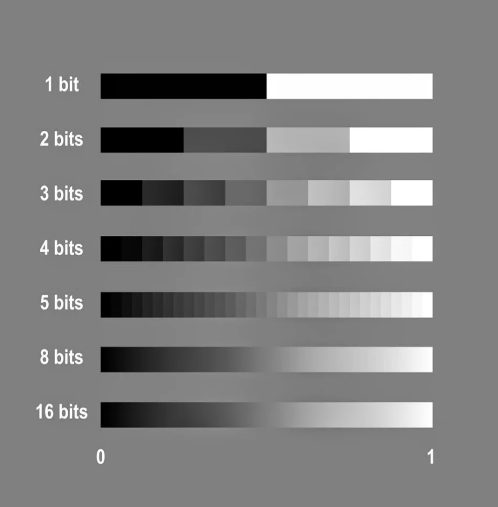
The number of bits per pixel that determines the shade of the pixel
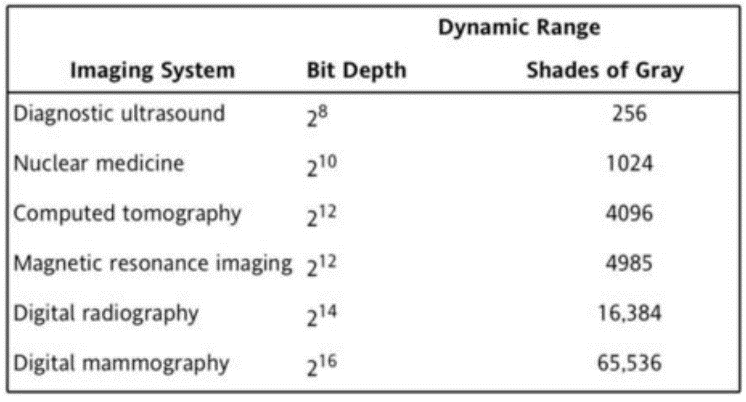
Most digital radiography systems use an 8, 10, or 12 bit depth
This is the number of bits that determines the amount of precision in digitizing the analog signal and therefore, the number of shades of gray that can be displayed in the image.
It is determined by the analog to-digital converter
Relationship: Increasing the number of shades of gray available to display on a digital image
improves its contrast resolution.An image with increased contrast resolution increases the visibility of recorded detail and the ability to distinguish among small anatomic areas of interest.
MATRIX
A square arrangement of numbers of columns and rows
In Digital Imaging, it corresponds to discrete values.
Each box within the matrix corresponds to
– A specific location in the image
– A specific area of the patient’s tissue.
FIELD OF VIEW
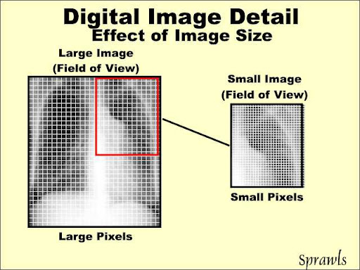
It describes how much of the patient is imaged in the matrix.
The larger the FOV, the greater the amount of body part is included in the image
The matrix size and the FOV are independent.
– Changes in either the FOV or the matrix size will change the pixel size.
RELATIONSHIP OF FOV, MATRIX SIZE, AND PIXEL SIZE
Field of View and Pixel Size = Directly proportional to each other (—>)
Matrix Size and Pixel Size = Inversely proportional to each other (<—)
Pixel Size and Spatial Resolution = Inversely proportional to each other (<—)
DETECTIVE QUANTUM EFFICIENCY
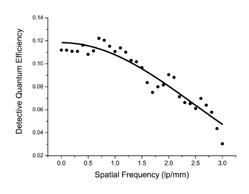
It is a measure of how efficient a digital detector can convert the X-rays collected from the patient into a useful image.
The DQE for a perfect digital detector is 1 or 100% meaning there was no loss of information.
Relationship: As spatial frequencies increase, the DQE decreases rapidly
EXPOSURE INDEX
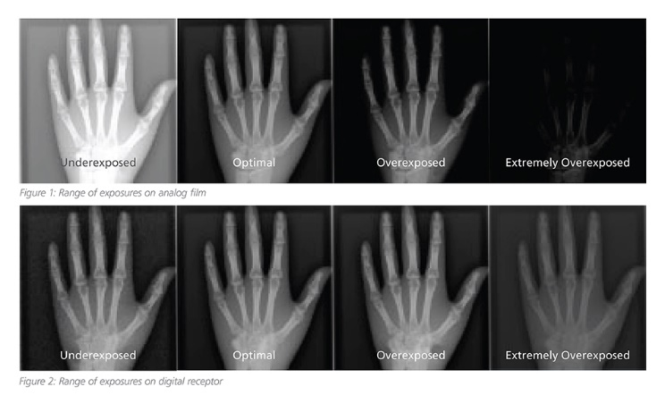
The exposure index is a measure of the amount of exposure on the image receptor.
In screen film radiography it is clear if the image receptor is too bright or too dark.
In digital radiography the image brightness can be altered.
SPATIAL RESOLUTION
The ability of the imaging system to allow two adjacent structures to be visualized as being separate or distinctness of an image to the image.
It refers to the smallest object that can be detected in an image and is the term typically used in digital imaging.
It is described as the ability of an imaging system to accurately display objects in two dimensions.
Note: In film/screen imaging the crystal size and thickness of the phosphor layer determine resolution; in digital imaging pixel size will determine resolution.
CONTRAST RESOLUTION
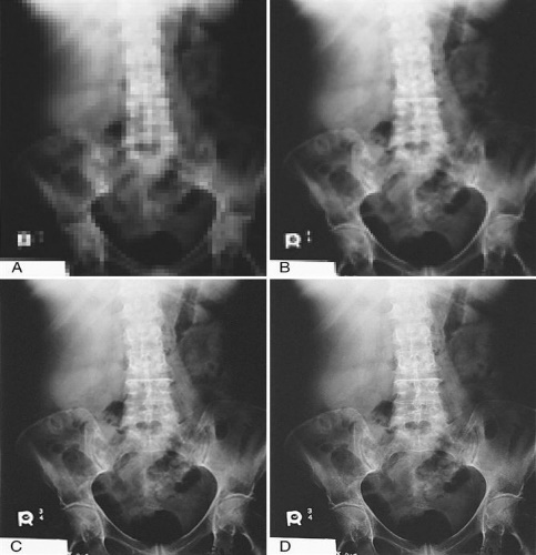
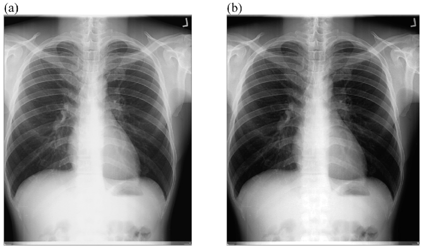
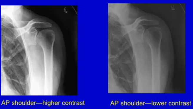
It is the ability to distinguish shades of gray from black to white.
It is used to describe the ability of an imaging receptor to distinguish between objects having
similar subject contrast.All digital imaging systems have a greater contrast resolution than screen film radiography.
The principal descriptor for contrast resolution is called the dynamic range
DYNAMIC RANGE
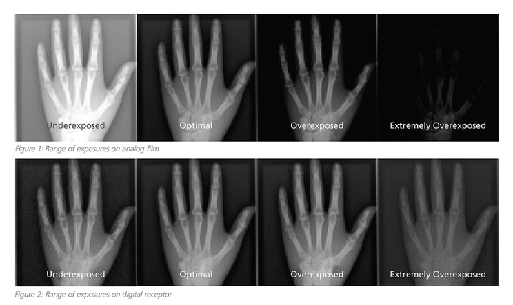
It refers the number of gray shades that an imaging system can produce.
It refers to the ability of the detector to capture accurately the range of photon intensities that exit the patient.
The dynamic range of digital imaging system is identified by the bit capacity of each pixel.
Typical digital systems will respond to exposures as low as 100 μR and as high as 100mR
SIGNAL-TO-NOISE RATIO
It is a method of describing the strength of the radiation exposure compared with the amount of noise apparent in a digital image.
Increasing the SNR improves the quality of the digital image.
DIGITAL RECEPTORS
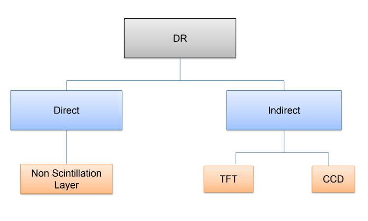
DIRECT VS INDIRECT CAPTURE
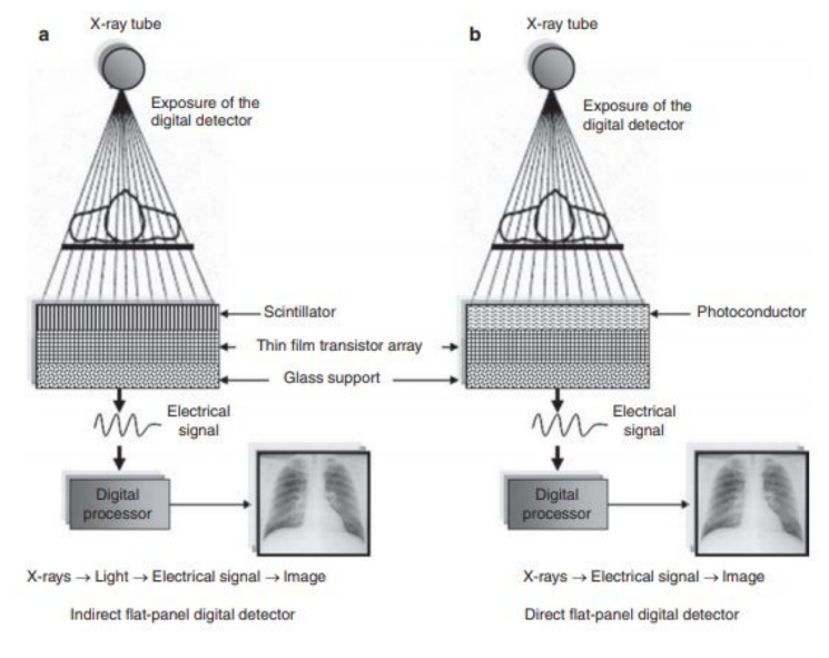
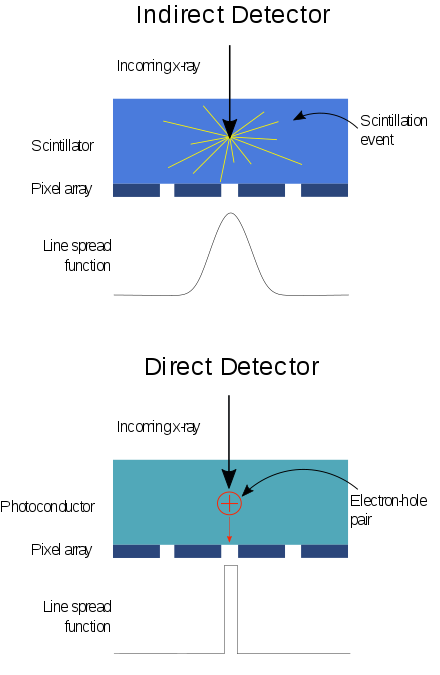
Direct Capture:
Converts the incoming x-ray photons to electrical signals
Indirect Capture:
Converts the incoming x-ray photons first to light then electrical signal to the final digital image.
Both of them use Flat Panel Detectors
FLAT PANEL DETECTORS OR DIGITAL RECEPTORS
Solid-state IRs that are constructed with layers in order to receive the x-ray photons and convert them to electrical charges for storage and readout
Signal storage, signal readout, and digitizing electronics are integrated into the flat panel device
Flat panel systems are highly dose-efficient and provide quicker access to images compared with CR and film-screen.
Spatial resolution of flat panel receptors is generally superior to the spatial resolution of CR.
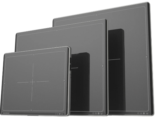
THIN FLAT PANEL DETECTORS FOR INDIRECT CAPTURE
It is composed of three layers:
Scintillation Layer
Photodiode layer
Thin Flat-Panel Transistor
SCINTILLATION LAYER
this is the layer wherein x-rays are converted into a small burst of light energy.
It is either made from Cesium Iodide or Gadolinium Oxysulfides
– Cesium Iodide is preferred material of the Scintillation layer because of its structure. Cesium iodide has a needlike structure (structured phosphor) that produces more focused light beam that increases spatial resolution compared to your gadolinium oxysulfide
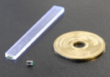
PHOTODIODE LAYER
This layer converts the incoming light photons into electric charge.
It is usually made made up of Amorphous Selenium (Amorphous = “without shape or form”)
The process of making this layer is known as plasma-enhanced chemical vapor deposition
where the amorphous silicon is a fluid that can be painted onto a supporting surface such as your glass substrate.
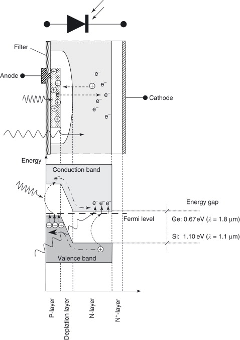
AMORPHOUS SELENIUM
It is the both the capture element and coupling element. This limits diffusion of electrons and maintains excellent spatial resolution.
The thickness of the amorphous selenium is relatively high approximately 200
um thick and sandwiched between charged electrons.
TFT LAYER
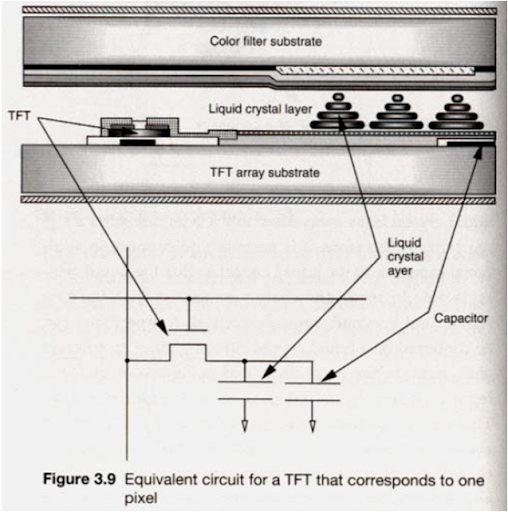
The electrical charges are temporarily stored by capacitors before being digitized and processed in the computer.
It’s is comprised of an array or matrix of digital elements (DEL)
Detector elements has three components the TFT, the capacitor, and
the sensing area.
- Capacitor – temporarily store the electrical charge
- TFT/Switch – acts to open and close the analog signal leaving each del.
CHARGED COUPLE DEVICE
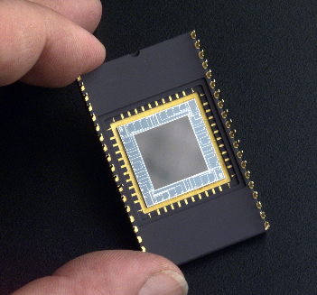
It was developed in the 1970’s as a highly sensitive device for military use.
It is the oldest indirect conversion radiography system to acquire a digital image.
It is a silicon-based semiconductor
CCD has three principal advantages.
Sensitivity - has a high sensitivity to respond to very low levels of visible light
Dynamic Range - detects wide range of light intensity from very dim light to intense light
Size - 1 to 2 cm
THIN FLAT PANEL DETECTORS FOR DIRECT CAPTURE
It is composed of two layers:
Semi-Conductor
Thin Film Transistor
DIGITAL DIRECT CAPTURE / NON SCINTILLATION
Semi Conductor
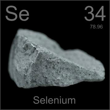
Amorphous Selenium
It is the both the capture element and coupling element
the thickness of the amorphous selenium is relatively high approximately 200
um thick and sandwiched between charged electrons.It is thick to compensate for the low atomic number of Selenium which is (34)
An electrical field is applied across the selenium layer to limit lateral diffusion of electrons as they migrate toward the thin-film transistor array. This means, excellent spatial resolution is maintained
PRELIM LECTURES ARE DONE! GOD BLESS ON YOUR EXAMS, FUTURE RRT!
— Sir Earl