Unit 3: Bridges & Spanning Trees
For this class, we’ll say bridges and switches are the same thing. In the traditional Ethernet context, bridges connect two or more LANs. Each port is isolated to be in its own collision domain. If each port has a full duplex point to point line, the CSMA/CD algorithm is not needed.
Many organizations have multiple LANs and wish to connect them. Different departments (like the departments at Harding, for instance) could have their own LAN for computers, servers, and printers. Since priorities may differ between departments, different LANs may be set up without regard for each other. On the other hand, the organization may be geographically spread over several buildings separated by considerable distances, and it may be cheaper to have separate LANs in each building. Another reason we might have many LANs is to accommodate a high load (splitting a single LAN into multiple).
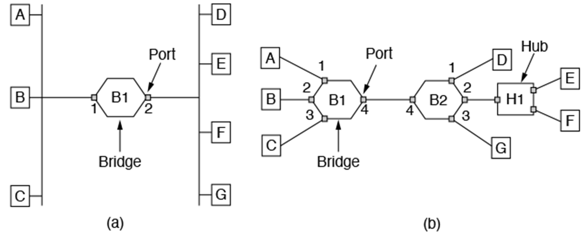
The image on the left is the more “classical” layout of a bridge setup. The image on the right is the more modern approach. For this class, we’ll mainly work on the older one because it is simpler and involves less parts, but the concepts can be applied to the newer model as well.
Transparent bridges are ways to interconnect IEEE LANs with complete transparency. In this context, it should be possible to get bridges, plug LAN cables into the bridges, and have everything work perfectly without changing hardware or software, setting address switches, or downloading routing tables or parameters. The operations of existing LANs should not be affected by the bridges at all.
Bridge Learning Algorithm: bridge has a table tracking where stations are. When it doesn’t know where the destination is, it passes the message along. When it learns where a station is located, it adds that location to its table. The passing along of messages is called flooding. Earlier in the process flooding is more common, it becomes less common as the bridges learn where stations are. The only way a bridge will learn where a station is is if it receives a message from that station.
To increase reliability, redundant links can be used. This involves intentionally putting multiple connections between networks, so that if something happens to one bridge, the whole network doesn’t fall apart. However, this comes with problems. Even if we imagine a world where collisions never occur and everything gets correctly sent and received, there are still problems with this setup. If bridge 1 hears a frame and doesn’t know where it’s going, it floods. If bridge 2 hears that frame and doesn’t know where it’s going, it floods. Bridge 1 might hear the same frame again from bridge 2’s flooding. We might have a giant loop of bridges re-sending the same frame over and over because they don’t realize it’s the same frame. Redundant links increase reliability but also cause loops, some of which will loop forever.
The solution to this is to pretend that we have a tree (even though we don’t). We treat the network like a tree to take out the loops. In spanning trees, both LANs and bridges will act as nodes (even though LANs visually look more similar to lines than nodes). Edges in the tree are defined by ports of bridges (edges connect nodes, ports connect bridges and LANs). We have to make a choice about which ports we will use. If we have a blocking port, we will pretend it doesn’t exist in the context of sending (we don’t send). We will still acknowledge new info learned via this port.
Spanning Tree poem by Perlman
Spanning Tree Algorithm:
Select a root bridge among all the bridges (bridge with the smallest number)
Determine the root port for all the other bridges (not the root bridge!)
They will pick the port closest to the root bridge (least cost path to root bridge)
Distance is expressed in hops/number of edges between bridge x and root bridge
If there is a tie in hops between two ports, the tiebreaker will be the smaller port number (port 1 and port 2 get you there equally as fast, just go with port 1)
Select a designated port for each LAN using the same logic
Pick the port closest to the root bridge
Distance expressed in hops
If there is a tie in hops between two ports, the tiebreaker will be the smaller bridge number
All root ports and designated ports are placed into a “forwarding” state. These are the only ports allowed to forward frames. The other ports are placed into a “blocking state” (they don’t send, but they still monitor and learn). If we lose a bridge, they may become backup options.
This algorithm ensures there are no loops. Some other observations: some places in the network experience a decrease in efficiency. Overall, however, the efficiency has increased- no more loops/broadcast storms. The tree likely won’t be balanced (doesn’t have much practical effects, but something to note). Because of the removing of pathways from sending, one bridge or port may become extremely busy and others may become very unbusy. The root bridge will always have all of its ports in a “forwarding state”. The other bridges may have only one or two bridges in this state. Important: there will be no ports that are both a root port and a designated port (they will either be only one or neither).
A benefit of this algorithm: if changes occur, we can just carry the algorithm out again and rearrange the network.