Electric Crcuits (OCR)
Electric Current
❂ The flow of charge is known as current.
❂ When two oppositely charged conductors are connected by a conductor, the charges will flow, producing a current.
❂ The greater the flow of charge, the greater the current.
❂ Current is the charge passing a point in a circuit every second.
❂ Current = Charge/Time
❂ The unit of current is Amperes (A)
❂ Current can be measured using an ammeter.
❂ Ammeters are always connected in series to the part of measurement.
❂ The flow of free electrons in a metal causes current.
❂ Electrons flow from negative to positive terminals.
❂ Conventional current flows from positive to negative terminals.
Electromotive Force
❂ The electromotive force is the work done in driving a charge around a complete circuit.
❂ It is the potential difference across the battery.
❂ It is measured in Volts (V).
❂ It is the energy per coulomb.
Potential Difference
❂ Potential difference is the work done in driving a charge through a component.
❂ It is measured in volts (V)
❂ It is the energy per coulomb
❂ Potential difference can be measured using a voltmeter.
❂ The voltmeter should be connect in parallel to the component of which the p.d is to be measured.
Resistance
❂ Resistance is the opposition to current
❂ The higher the resistance, the lesser the current.
❂
❂ V = IR
❂ Resistance is measured in ohms
❂ To measure the resistance of a component, the current is measured by attaching an ammeter in series and potential difference is measured by attaching a voltmeter in parallel.
❂ The readings are used to calculate the resistance by R=V/I
❂ Resistance is caused when the electrons flowing in a metal collide with the metal’s ions.
❂ The longer the wire, the greater the resistance.
❂ The greater the cross sectional area of the wire, the lesser the resistance.
❂ Resistance is directly proportional to the length, and inversely proportional to the area.
Electrical Power
❂ Power is the rate of energy transfer
❂
❂ P=IV
❂ The unit of power is Watt (W)
❂ Watt is the the same as Joules/second
❂
Ohm’s Law
❂ Ohm’s law states that resistance is directly proportional to current when physical conditions such as the temperature are constant.
❂ If the temperature varies, such as in a filament lamp, it will not obey ohm’s law.
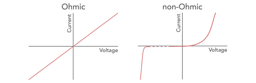
❂ Resistors that obey Ohm’s law are known as ohmic resistors.
❂ Resistors that do not obey Ohm’s law are non-ohmic.
❂ The IV graph of an ohmic graph is a straight line.
❂ The graph of non-ohmic conductors is curved towards the voltage.
❂ In non-ohmic conductors such as filament lamp, the temperature increases with time.
❂ The temperature causes the resistance to increase.
❂ A higher resistance means a lower current.
Capacitors
Store electrical energy in an electric field.
Capacitance (C): Measured in Farads (F).
Inductors
Store energy in a magnetic field.
Inductance (L): Measured in Henrys (H).
Series Circuits
❂ Components are connected next to each other in series.
❂ The current is same at all points in a series circuit.
❂ The total EMF for batteries connected in series is the sum of their individual EMFs.
❂ In a series circuit, the sum of the p.d of individual components is equal to the total emf.
❂ If one component stops working, the whole circuit doesn’t work.
❂ the total resistance in a series circuit is the sum of all individual resistances.
Parallel Circuits
❂ The components are attached on separate branches.
❂ Components can be individually controlled.
❂ if one component stops working the rest will continue to function.
❂ The current splits up in parallel circuits.
❂ The sum of currents in each branch is equal to the emf.
❂ The current does not split equally always.
❂ The potential difference is same in every branch.
❂ Resistors connected in parallel have decreased resistance.
❂ If two identical resistors are attached in parallel, the resistance is will be half of one component.
❂ The reciprocal of the total resistance is equal to the sum of the reciprocals of the individual resistors.
❂
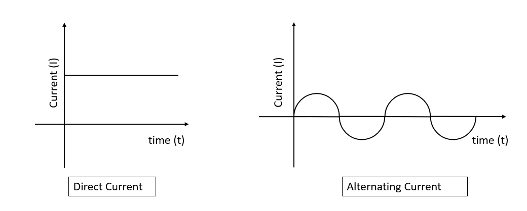
Alternating vs Direct Current
❂ Alternating current constantly changes direction, going back and forth in a circuit.
❂ A direct current flows in one direction only.
❂ A current time graph for dc current is flat line.
❂ A current time graph for ac current is similar to a transverse wave.
❂ Batteries produce direct current.
❂ Mains electricity carries alternating current.
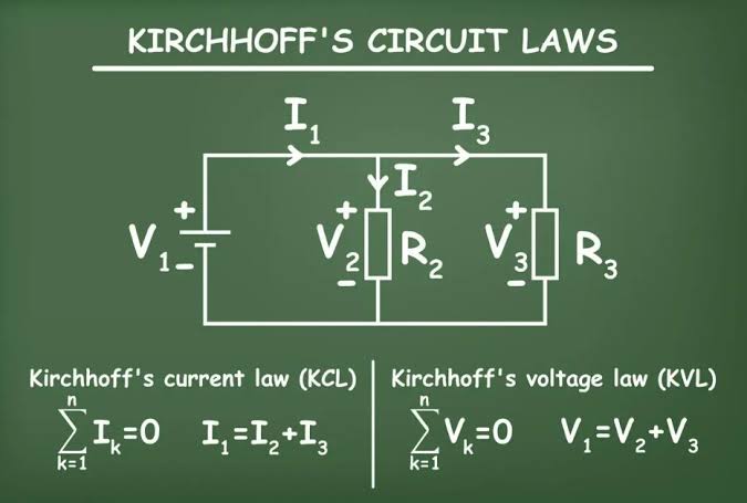
Kirchhoff’s Laws
Kirchhoff’s Current Law (KCL)
The total current entering a junction equals the total current leaving the junction.
Kirchhoff’s Voltage Law (KVL)
The sum of all voltages around a closed loop equals zero.
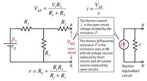
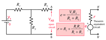
Thevenin’s Theorem:
Thevenin’s Theorem states that any linear electrical network with voltage sources and resistances can be replaced at terminals A-B by an equivalent voltage source.
Steps to Find Thevenin Equivalent Circuit
Remove the Load Resistor: Temporarily remove the resistor across the terminals where you want to find the Thevenin equivalent.
Find Thevenin Voltage: This is the open-circuit voltage across the terminals A-B (without the load resistor).
Use any method like voltage division, mesh analysis, or nodal analysis.
Find Thevenin Resistance:
Deactivate all independent sources: Replace voltage sources with short circuits and current sources with open circuits.
Calculate the equivalent resistance across the terminals A-B.
Construct the Thevenin Equivalent Circuit: Connect in series and reattach the load resistor.
Norton’s Theorem:
Norton’s Theorem states that any linear electrical network with voltage sources and resistances can be replaced at terminals A-B by an equivalent current source in parallel with a resistance.
Steps to Find Norton Equivalent Circuit
Remove the Load Resistor: Temporarily remove the resistor across the terminals where you want to find the Norton equivalent.
Find Norton Current: This is the short-circuit current through the terminals A-B (with the load resistor removed).
Short the terminals A-B and calculate the current using any method like current division, mesh analysis, or nodal analysis.
Find Norton Resistance:
Deactivate all independent sources: Replace voltage sources with short circuits and current sources with open circuits.
Calculate the equivalent resistance across the terminals A-B.
Construct the Norton Equivalent Circuit: Connect in parallel and reattach the load resistor.