Week 9 Lecture 2: More B-Mode Imaging Artifacts
Depth Artifacts
Occur due to the incorrect depth display of tissues.
Types:
Propagation speed artifact
Reverberation artifact
Ring down artifact
Comet tail artifact
Range ambiguity artifact
Violated assumptions:
The transmitted wave travels along a straight line path from the transducer to the object and back to the transducer.
The round trip time is 13 microseconds for every cm of depth.
Propagation Speed Artifact
The ultrasound system calculates depth based on the propagation speed of tissue, assuming it's a constant (1540 m/s).
If the actual propagation speed is slower, the returning echo takes longer to arrive, and the system displays the echoes deeper than they are.
(u = 0.0022)
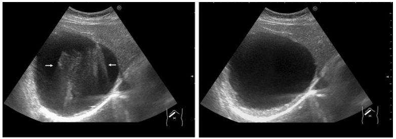
Range Ambiguity Artifact
Occurs when all echoes are not received before the next pulse is sent.
The system assumes all echoes are from the most recently transmitted pulse and places objects more superficially than they are.
Often seen with superficial cystic structures.
Can be mitigated by altering depth or PRF (Pulse Repetition Frequency) or using a lower frequency transducer.
Superficial reflected sound energy arrives at the transducer before a second sound pulse is generated
Deeper (delayed) arrive at the transducer after the transmit of the new pulse
The system interprets the echoes returning from depth as being associated with the second pulse
The system places these echoes in the image near field, assuming these are early returning pulses from the second pulse
Alter depth or PRF/utilize lower frequency transducer
Reverberation Artifacts
Tissues are displayed multiple times at equally spaced depths due to repeated reflections.
Only the first reflection is spatially correct.
Characteristics:
Parallel to the sound beam’s main axis.
Decreasing in intensity.
Equidistant from each other.
Echoes can appear between the transducer and a strong reflector or between two strong reflectors.
Types:
Simple reverberation
Ring-down artifact
Comet-tail artifact
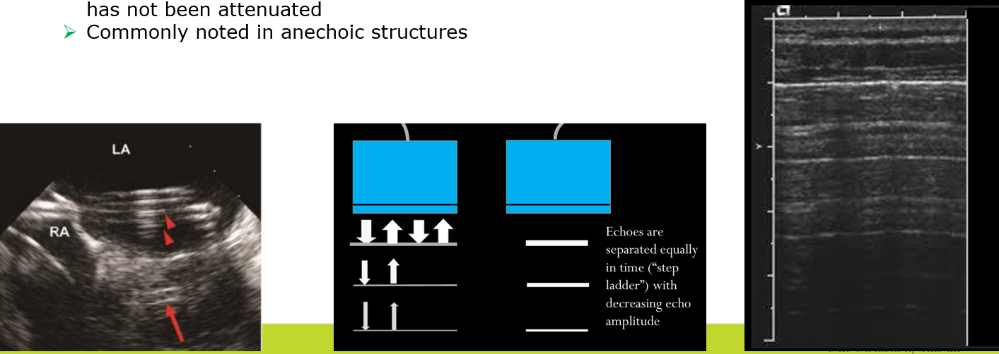
Simple Reverberation Artifact
Sound bounces between the transducer and a strong specular reflector, or between two strong specular reflectors.
Often called “reverb.”
More common in superficial tissues where the sound beam has not been attenuated.
Commonly noted in anechoic structures.
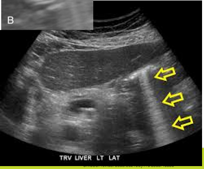
Ringdown Artifact
Reflectors are gas bubbles.
Multiple echoes are seen due to sound reverberating back and forth between air/soft tissue interfaces and within gas bubbles.
Strong, bright, repeating lines are observed deep to gas bubbles.
Comet Tail Artifacts
Multiple echoes from repeated reflections within a small but highly reflective object.
The artifact decreases in amplitude and width (tapers and fades) as it gets deeper.
Often seen with metal, crystalline materials.
Beam Dimension Artifacts
Types:
Beam width artifact
Slice thickness artifact
Side lobe/grating lobe artifact
Violated assumptions:
All detected echoes originate from the axis of the main beam only, and beam dimensions are small in both section thickness (elevational) and lateral directions.
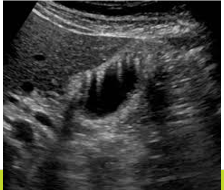
Beam Width Artifact
A strong reflector located within the widened beam beyond the margin of the transducer will generate detectable echoes.
These echoes are assumed to have originated from the narrow imaging plane and are displayed as such.
Occurs because of beam width divergence beyond the focal zone.
Typically seen in anechoic structures, e.g., gas shadowing seen “within” the bladder.
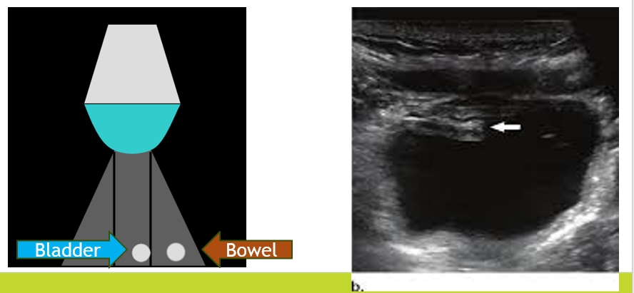
Slice Thickness Artifact
Similar to the beam width artifact but occurs due to the thickness (elevational plane) of the beam.
Often seen within anechoic structures at depth when adjacent bowel and bladder are contained within the same “slice thickness.”
Side Lobe/Grating Lobe Artifact
A strong reflector in a side lobe (single crystal transducer) or grating lobe (array transducer) can appear as an echo as if it arises from the central beam.
Example: Bowel with reverberation artifacts is misregistered in an anechoic ovarian cyst.
Beam Path Artifacts
Types:
Refraction artifact
Mirror image artifact
Violated assumptions:
The transmitted wave travels along a straight line path from the transducer to the object and back to the transducer.
All detected echoes originate from the axis of the main beam only, and the depth of objects is proportional to the round-trip time.
Refraction Artifact
The ultrasound system assumes that the beam has traveled in a straight line, but refraction has “bent” the beam due to Snell’s Law.
Refraction artifacts cause lateral displacement of reflectors.
Mirror Image Artifact
Duplication of a structure on either side of a strong specular reflector.
The true reflector and the false object are equal distances from the “mirror,” with the false object placed deeper on the image.