CHAPTER 15 (1): RC CIRCUITS
Chapter 15: RC Circuits (Part 1)
Series RC Circuits
RC Circuit Overview
The chapter focuses on understanding series RC circuits, including their analysis and implications in AC circuits.
Learning Objectives
After completing Part 1, you will be able to:
Analyze a series RC circuit.
Determine AC impedance of a series RC circuit.
Understand the phase relationship between voltages and current in the circuit.
Draw impedance and phasor diagrams related to the circuit.
Main Topics Covered
Analysis of Series RC Circuits (Part 1)
Analysis of Parallel RC Circuits (Part 2)
Power and Power Factor in RC Circuits (Part 2)
Key Concepts of RC Circuits
Impedance
Impedance
In an AC circuit, opposition to current flow is called impedance, measured in ohms (Ω).
Impedance of a resistor (R) is real, while impedance of a capacitor is represented as -jXC (imaginary), where XC is capacitive reactance.
Circuit Laws and Impedance Calculations
Impedance of Series RC Circuit
Total impedance in a series RC circuit:
Z = R - jXC
Real part from resistors and imaginary part from capacitors.
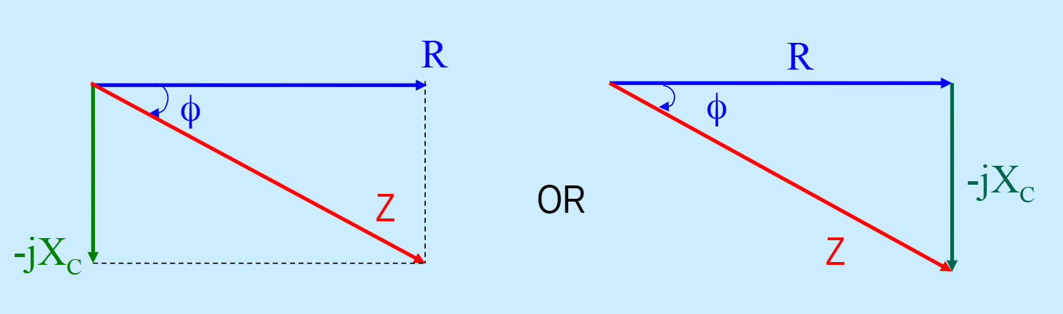
Impedance Diagram
An Impedance Diagram summarizes all impedances in the circuit and provides an insightful visual representation. (Vector Diagram)
Example 15-1: Calculation of Impedance
Problem: Find the impedance of a series circuit with R = 100Ω, C = 2mF, and a 500Hz AC source.
Solution Steps:
Use relevant formulas to determine total impedance.
Voltages and Current Relationships in Series RC Circuit
Common Electrical Quantity: Current (I) is a reference phasor in series circuits.
Voltage Relationship:
Apply Kirchhoff's Voltage Law: V₁ = V₂ + V and Ohm's Law.
Various formulas show relations between circuit currents and voltages:
V₁ = IZ
V₁ = ĪR
V₁ = Ī(-jXC)
Phasor Diagrams
Phasor Diagram shows the phase relationships of voltage and current:
Describe how voltages, such as VR, V, and VC, relate to the current I.
Relationship between Impedance and Phasor Diagrams
Impedance diagram and phasor diagram are similar, representing the circuit's impedance when multiplied by current.
The phase of the circuit impedance matches the applied voltage phase.
Analysis Procedure for Series RC Circuits
Calculate circuit impedance: Z = R - jXC
Calculate the total current in the circuit.
Calculate voltage across the resistor VR and the voltage across the capacitor VC.
Draw phasor and impedance diagrams if necessary.
Example 15-2: Practical Scenario
Given: 10V, 1.5kHz AC source connected to a series RC circuit where R = 2.2kΩ & C = 0.02mF.
Tasks:
Draw the phasor domain schematic diagram.
Draw the impedance diagram.
Draw the phasor diagram.
Write down time domain sinusoidal expressions for voltage and current.
Solutions for Example 15-2
Calculate reactance and total impedance.
Convert to polar form and summarize voltages and currents.
Summary
The impedance of a series RC circuit is Z = R - jXC.
Circuit current leads the source voltage by a phase angle of ϕ.
Conclusion
Understanding series RC circuits is crucial in AC circuit analysis and facilitates resolving practical electrical challenges.