L12: Eutectoid Decomposition / Pearlite
Learning Objectives:
-Be able to describe the sequence of pearlite formation
Localised hypo/hyper eutectoid favours growth, which depletes one element locally, initiating other phase
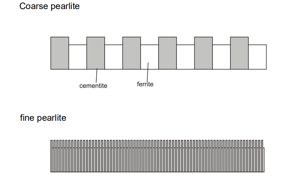
Means two phases are closely intermixed
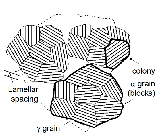
A colony is a region of consistent OR between α and Fe3C
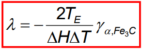
- Be able to predict the minimum pearlite spacing that can form in given heat treatment
Driving force must exceed the interfacial energy
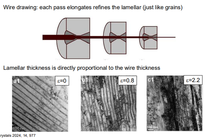
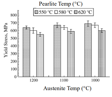
High undercooling=finer pearlite (can be further refined through deformation)
- Describe how the spacing and other microstructural features may effect properties.
Finer pearlite = harder and more brittle
Finer block size also has a minor hardening effect
- Understand why pearlite appears brown in Light Microscope
Etch pits prevent light escaping (finer spacing=narrower pits)
Sequence of Pearlite Formation:
Pearlite is a eutectoid mixture of ferrite (α-iron) and cementite (Fe₃C) that forms when austenite (γ-iron) with 0.8 wt% carbon is cooled below the eutectoid temperature (727°C).
The formation of pearlite begins with the nucleation of cementite on austenite grain boundaries. This nucleation depletes the surrounding region of carbon, creating a driving force for ferrite to nucleate adjacent to the cementite.
The ferrite and cementite grow cooperatively, forming alternating lamellae (layers) of ferrite and cementite. This cooperative growth is driven by the diffusion of carbon atoms from the ferrite to the cementite.
If the steel does not have the exact eutectoid composition (0.8 wt% C), pre-eutectoid ferrite or cementite will form first on the grain boundaries, and pearlite will nucleate on these pre-existing phases.
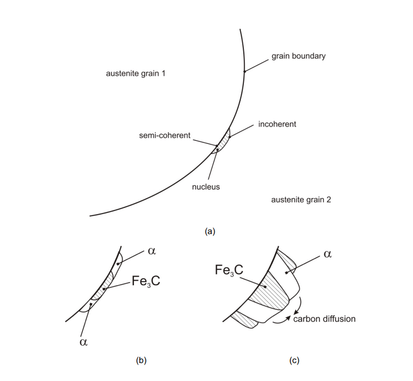
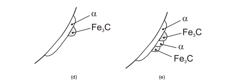
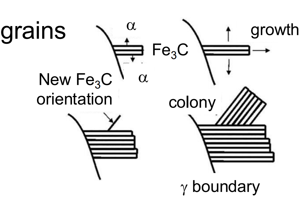
Colonies, Blocks, and Grains: The image depicts the growth of pearlite colonies, which consist of alternating ferrite (α) and cementite (Fe₃C) lamellae. These colonies form within austenite (γ) grains.
Fe₃C Orientation Changes: The orientation of cementite (Fe₃C) changes during growth, while the ferrite orientation remains conserved due to its high symmetry and major phase fraction in pearlite.
Blocks Join Together: Multiple blocks (regions of pearlite) grow and join together to fill the austenite grains. Each block originates from a different nucleus.
Lamellar Structure: The pearlite exhibits a lamellar structure, with alternating layers of ferrite and cementite, growing within the austenite grain boundaries.
2. Minimum Pearlite Spacing:
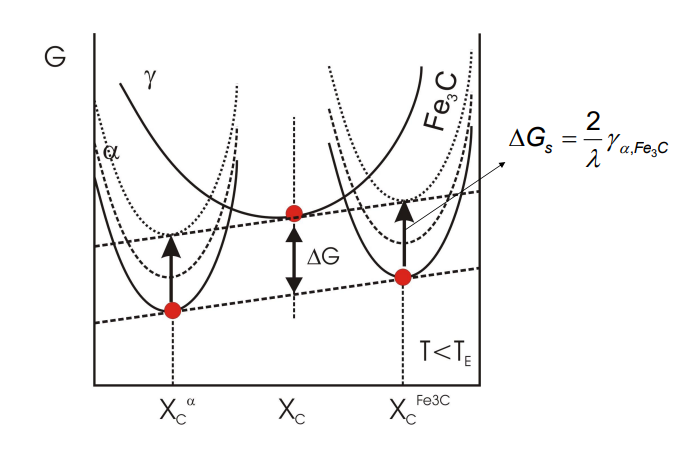
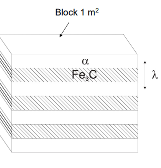
-Interfacial energy per unit vol of pearlite reduces free energy of transformation.
-Increased interfaces => free energy of transformation → 0.
The interlamellar spacing (λ) of pearlite is the distance between adjacent cementite and ferrite layers. It is not fixed and depends on the undercooling (ΔT) during cooling.
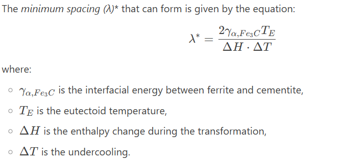
As the undercooling increases, the spacing decreases, meaning that faster cooling rates result in finer pearlite.
Other ways to refine microstructure other than cooling:
3. Effect of Spacing and Microstructural Features on Properties:
Finer pearlite (smaller interlamellar spacing) generally results in higher strength and hardness due to the increased number of interfaces (grain boundaries) that impede dislocation movement.
Coarser pearlite (larger spacing) tends to be less strong but more ductile because the larger spacing allows for easier dislocation movement.
The morphology of pearlite (e.g., lamellar vs. spheroidized) also affects properties. Lamellar pearlite is stronger but less ductile, while spheroidized pearlite (where cementite forms as spherical particles) is more ductile but less strong.
4. Why Pearlite Appears Brown in Light Microscopy (LM):
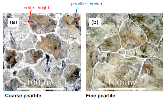
Pearlite appears brown in light microscopy due to the etching process used to reveal the microstructure. The etchant reacts differently with the ferrite and cementite phases, creating a contrast between the two.
Ferrite, being softer, etches more quickly and appears lighter, while cementite, being harder, etches more slowly and appears darker. The combination of these contrasting phases gives pearlite its characteristic brownish appearance under the microscope.