L6: Mechanic response of discontinuous composites
Learning Objectives:
Describe the origin of the shear-lag model for composites with short reinforcement
Understand the significance of the stress transfer length concept and be aware that the optimal aspect ratio changes with material stiffnesses
Explain the differences between the possible architectures a porous material can be modelled with (honeycomb, closed/open cell)
Select which structure is mechanically more efficient
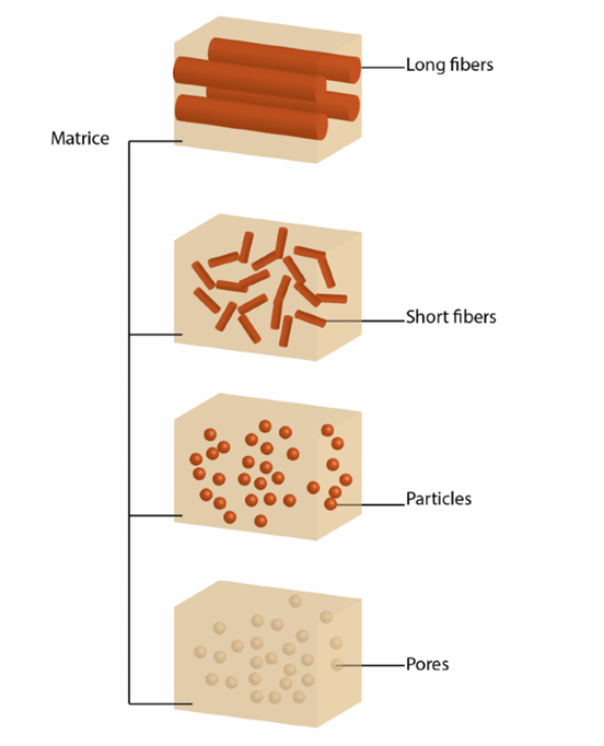
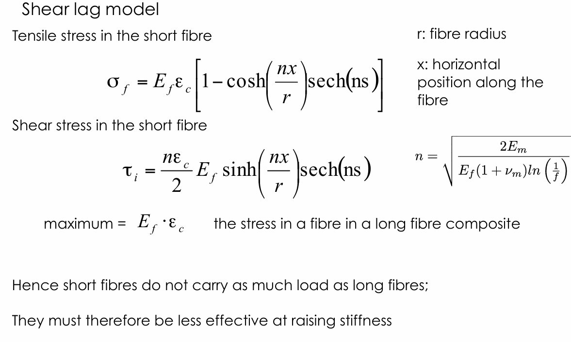
Shear-Lag Model for Short Fibre Composites:
Origin:
Explains how stress is transferred from the matrix to short fibres via interfacial shear.
Short fibres cannot span the entire material, so stress transfer occurs through shear at the matrix-fibre interface.
Implications:
Short fibres carry less load than long fibres.
Stress transfer depends on the aspect ratio (length/diameter) of the fibre.
2. Stress Transfer Length Concept:
Definition:
The length over which stress builds up from zero at the fibre ends to a maximum value.
Significance:
Determines how effectively the fibre can carry load.
Optimal aspect ratio depends on material stiffnesses:
Polymer matrix composites: s∼30
Metal matrix composites: s∼7
Ceramic matrix composites: s∼3
Key Point:
Higher aspect ratios are needed for efficient stress transfer in less stiff matrices.
The aspect ratio required for the maximum stress to be equal to the peak stress
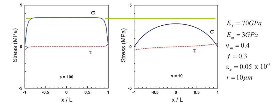
These graphs show the normal (σ, blue) and shear (τ, red dashed) stress distribution along a fibre in a composite under load.
Left (s = 100, strong interface):
σ is nearly uniform, dropping at fibre ends.
τ is small, concentrated near fibre ends.
Right (s = 10, weak interface):
σ forms a parabolic shape, peaking at the centre.
τ is more evenly distributed and higher overall.
A strong interface ensures efficient load transfer, while a weak interface leads to more gradual stress variation.
3. Porous Material Architectures:
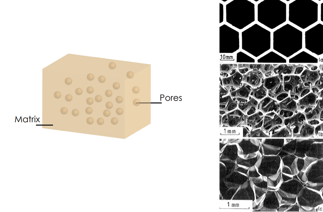
Honeycomb Structures:
Regular, repeating hexagonal cells.
High in-plane stiffness and strength.
Used in lightweight structural applications.
Open-Cell Foams:
Consist of interconnected struts.
Allow fluid flow, suitable for thermal insulation or filtration.
Closed-Cell Foams:
Sealed cells, can contain gas or fluid.
Provide better stiffness and strength compared to open-cell foams.
Less permeable than open-cell foams.
4. Mechanical Efficiency of Structures:
Honeycombs:
More efficient for in-plane loading.
High stiffness and strength-to-weight ratio.
Closed-Cell Foams:
More efficient for out-of-plane loading.
Better overall stiffness and strength compared to open-cell foams.
Open-Cell Foams:
More efficient for applications requiring permeability (e.g., thermal insulation, filters).
Properties of porous materials are denoted with a superscript asterisk (X∗).
Xdir∗: Property of the porous material in a specific direction.
Xdir: Property of the dense (non-porous) material.
5. Stress Transfer through Shear and Contact:
Stress is transferred through shear at the matrix-fibre interface.
Key Requirement:
Sufficient contact between the matrix and fibre is necessary for effective load transfer.
Implication:
The more contact between the matrix and fibre, the more effectively the fibre can carry load