CISCO 1 (incomplete)
MODULE 1 (Networking Today)
Communication is almost as important to us as our reliance on air, water, food, and shelter.
Networking today has no boundaries, which connects global communities and create human network.
Network Components
HOST ROLES
every computer on a network is called a host or end device.
Servers are computers that provice information to end devices:
email servers
clients use client software to access email
web servers
clients use browser software to access web pages
file server
stores corporate and user files; client devices access these files
Clients are computers that send requests to the servers
PEER-TO-PEER
A device to be a client and a server in a peer-to-peer network
ADVANTAGES
Easy to set up
Less complex
Lower cost
used for simple tasks
DISADVANTAGES
no centralized administration
not as secure
not scalable
slower performance
END DEVICE
A message originates fromor where it is received.
data from end device → network → another end device
INTERMEDIARY NETWORK DEVICES
it interconnects end devices
ex. switches, wireless access points, routers, and firewalls
ROLE OF AN INTERMEDIARY DEVICE:
management of data as it flows through a network
regenerate and retransmit data signals
maintain information about what pathway exist
notify other devices of errors
NETWORK MEDIA
communication is carried through a medium
MEDIA TYPES
Metal wires within cables
uses electrical impulses
Glass or plastic fibers within cable (Fiber-optic cable)
pulses of light
wireless transmission
uses modulation of specific frequencies of electromagnetic waves.
Network Representations and Topologies
NETWORK REPRESENTATIONS
NETWORK DIAGRAMS/TOPOLOGY DIAGRAMS
uses symbols to represent devices within the network
Important Terms:
Network Interface Card (NIC)
Hardware that connects a device to a network
Physical Port
socket on a device where cables are plugged in
Interface
connection point used for network communication
TOPOLOGY DIAGRAMS
PHYSICAL TOPOLOGY
illustrates the physical location of intermediary devices and cable installation
LOGICAL TOPOLOGY
illustrates devices, ports, and the addressing scheme
Common Types of Networks
NETWORK OF MANY SIZES
Small Home Networks
Connects a few computers to each other and the internet
Small Office/Home Office
enables computer within a home or remote office to connect to a corporate network
Medium to Large Networks
hundreds or thousands of interconnected computers
World Wide Network
connects hundreds of millions of computers world wide (Internet)
LANs AND WANs
LAN (Local Area Network)
spans a small geographical area
limited area
administered by a single organization or individual
provide high-speed bandwidth
WAN (Wide Area Network)
spans a wide geographical area
interconnect LANs over wide geographical areas
administered by one or more service providers
provide a slower sleep links between LANs
INTERNET
worldwide collection of interconnected LANs and WANs
LANs are connected to each other using WANs
WANs may use copper wires, fiber optic cables, and wireless transmissions
not owned by any individual or group
developed to maintain structure on the internet:
IETF (Internet Engineering Task Force)
develops and maintains internet standards and protocols
ICANN (Internet Corporation for Assigned Names and Numbers)
manages domain names and IP address allocation
IAB (Internet Architecture Board)
Oversees the technical development and architecture
INTRANETS AND EXTRANETS
INTRANET
private collection of LANs and WANs internal
accessible only to the organizations members or others with authorization
EXTRANET
for individuals who work for a different organization that need access to their data on their network.
Internet Connections
INTERNET ACCESS TECHNOLOGIES
ways to connect users and organizations to the internet:
Broadband cable, broadband digital subscriver line (DSL), wireless WANs, and mobile servies are used for home users and small offices.
Organizations need faster connections
business-class interconnections are usually provided by service providers (SP) (may include business DSL, leased lines, and metro ethernet)
HOME AND SMALL OFFICE INTERNET CONNECTIONS
Connections:
Cable
internet offered by cable television service providers
DSL (Broadband digital subscriber)
runs over a telephone line)
Cellular
cellphone network
Satellite
major benefit to rural areas without internet service providers
Dial-up telephone
uses modem
BUSINESS INTERNET CONNECTIONS
Requires:
higher bandwidth
dedicated connections
managed services
Types of Connection
Dedicated Leased Line
reserved circuites within the service provider’s network
connects distant offices
Ethernet WAN
extends LAN access technology into the WAN
DSL
available in various formats including Symmetric Digital Subscriber Lines (SDSL)
Satellite
provides connection when a wires solution is not available
THE CONVERGING NETWORK
carries multiple services on one link:
data
voice
video
can deliver over the same network infrastructure
Reliable Networks
NETWORK ARCHITECTURE
technologies that support infrastructure that moves data across the network
4 basic characteristics to meet user expectations:
Fault Tolerance
limits the impact of a failure
limiting the number of affected devices
multiple paths are required for fault tolerance
Packet Switched Network:
splits traffic into packets that are routed over a network
each packet could theoretically take a different path to the destination
* Not possible with circuit-switched networks
Scalability
expands quickly and easily to support new users and applications
Quality of Service
primary mechanism used to ensure reliable delivery of content
with QoS policy in place, the rother can more easily manage the flow of data and voice traffic
Network Security
2 main types of network security
Network infrastructure security
physical security of network devices
prevents unauthorized access
Information security
protects the information or data transmitted
3 main goals
confidentiality
only intended recipients can read the data
integrity
assurance that the data has not been altered during transmission
availability
assurance of timely and reliable access
Network Trends
Recent Trends
Bring your Own Device (BYOD)
allows end users to have the freedome to user personal tools to access information and communicate
gives them more opportunities and greater flexibility
any device, used anywhere
Online Collaboration
collaborate over the network on joint proects
Video Communication
video call are made to anyone
powerful tool for communicating with others
video is becoming critical requirement
Cloud Computing
stores personal files
backups our data on servers over the internet
allows businesses to deliver to any device anywhere in the world
4 types of clouds:
Public Coulds
available to the general public
Private Clouds
for specific organizations
hybrid clouds
made up of 2 or more cloud types (ex. part custom and part public)
custom clouds
built to meet the needs of a specific industry
can be private or public
TECHNOLOGY TRENDS IN THE HOME
smart home technology
allows technology to be integrated into every-day appliances
POWERLINE NETWORKING
allows devices to connect to a LAN where data network cables or wireless communications are not a viable option
useful when wireless access points cannot reach all the devices in the home
WIRELESS BROADBAND
another option used to connect homes and small businesses to the internet
Wireless Internet Service Provider (WISP connects subscribers to designated access points or hotspots (Commonly found in rural environments)
another solution for the home and small businesses
an antenna is installed outside the hosue
Network Security
SECURITY THREATS
an integral part of networking regardless of the size of the network
must take into account the environment
involves many protocols, technologies, devices, tools, and techniques to secure data
threat vectors might be external or internal
external threats (outside the organization):
viruses, worms. tojan horses
spyware and adware
zero-day attacks
threat actor attacks
denial of service attacks
data interception and theft
identity theft
internal threats (inside the organization):
lost or stolen devices
accidental misuse by employees
malicious employees
SECURITY SOLUTIONS
additional security reqs.:
dedicated firewall system
access control lists (ACL)
intrusion prevention systems (IPS)
Virtual private networks (VPN)
MODULE 2 (Basic Switch and End Device Configuraiton)
Cisco IOS Access
OPERATION SYSTEMS
shell
allows users to request specific tasks from the computer
kernel
communicates between the hardware and software of a computer
hardware
physical part of a computer
GUI
allows users to interact with the system using graphical icons, menus, and windows
user friendly and requires less knowledge
can failm crash, or simply not operate as specified
network devices are typically accessed through CLI
PURPOSE OF AN OS
allows users to use a mouse to make selections and run programs
allows users to enter text and text based commands
CLI based network OS enables a network technician to:
use keyboard to run CLI based network programs
use keuboard to enter text and text based commands
view output on a monitor
ACCESS METHODS
console
physical management port
secure shell (SSH)
establishes a secure remote CLI connection through virtual interface
telnet
establishes an insecure remote CLI connection
TERMINAL EMULATION PROGRAMS
used to connect to a network device by either a console port or by an SSH/Telnet connection
IOS Navigation
PRIMARY COMMAND MODES
user EXEC mode:
allows acces to only a limited number of basic monitoring commands
identified by the CLI prompt that ends with the > symbol
privileged EXEC mode:
allows access to all ommands and features
ends with the # symbol
CONFIGURATION MODE AND SUBCONFIGURATION MODES
gloval configuration mode:
used to access configuration oprtions
line configuration mode:
used to configure console, SSH, telnet, or AUX access
interface configuration mode:
used to configure a switch port or router interface
NAVIGATION BETWEEN IOS MODES
privileged EXEC mode:
moves from user EXEC mode to privilede EXEC mode
use the enabled command
global configuration mode:
move in and out of global configuration mode
use the configure terminal command
to return to privilege EXEC mode, use exit command
line configuration mode:
move in and out of configuration mode
line command followed by the management line type
use exit command to return to global config mode
subconfiguraiton modes:
to move out of any subconfig mode to return to global config mode, use exit command
to return to privilege EXEC mode, use end command or key combination ctrl + z
to move directly from one subconfig mode, type the desired subconfig mode command
ex. (config-line)# to (config-if)#
The Command Structure
BASIC IOS COMMAND STRUCTURE
keyword
a specific parameter defined in the operating system (ip protocols)
argument
not predefined; value defined by the user (192.168.10.5)

ex.
prompt → switch
command → show
space
keyword → ip protocols
argument → 192.168.10.5
IOS COMMAND SYNTAX CHECK
a command might require one or more args.
boldface
indicated commands and keywords that you enter literally as shown
italics
you supply values
[ ]
indicates an optional element
{ }
indicates a required element
[ { | } ]
indicates required choice within an optional element.
spaces are used to clearly delineate parts of the command
command syntax provides the pattern, or format that must be used when entering a command
IOS HELP FEATURES
2 forms of help available:
context-sensitive help
enables you to quickly find answers to these questions:
which commands are available in each command mode
which commands start with specific characters or group of characters
which argument and keuwords are available to aprticular commands
ex.

command syntax check
verifies that a valid command was entered by the user
ex.

HOT KEYS AND SHORTCUTS
IOS CLI privdes hotkeys and shortcuts
commands and keywords can be shortened to the minimum number of characters that indetify a unique selection
keystrokes
tab
completes a partial command name entry
backspace
erases the character to the left of the cursor
left arrow or ctrl+b
moves the cursor one character to the left
right arrow or ctrl f
move the cursor one character to the right
up arrow or ctrl p
recalls the commands in the history buffer
enter key
displays the next line
space bar
next screen
any other key
ends the display string, returning to privileged EXEC mode
ctrl c or ctrl z
ends the config mode and returns to privileged EXEC mode
ctrl shift 6
all purpose break sequence used to abort DNS lookups, traceroutes, pings, etc.
Basic Device Config
DEVICE NAMES
first config command should be to give it a unique hostname
all devices are assigned a factory default name
ex. Cisco IO
S switch is “switch”
Guidelines for naming devices:
start with a letter
contain no spaces
end with a letter or digit
use only letters, digits, and dashes
less than 64 characters
PASSWORD GUIDELINES
all networking devices sould limit administrative access by securing priveleged EXEC, user EXEC and remove Telnet access with passwords
Password Guidelines:
more than 8 characters
use a combination of upper and lowercase letters, numbers, special characters, and/or numeric sequence
avoid using the same pass. for all devices
do not use common words
CONFIG PASSWORDS
securing user EXEC mode access:
enter line console 0 in global config mode
specify the user EXEC mode password using the password command
enable user EXEC access using the login command

securing privileged EXEC mode access:
enter global config mode
use the enable secret password command

securing VTY line access:
enter line VTY config mode using the line vty 0 15 command in global config mode
specify VTY password using the password command
enable VTY access using the login command

ENCRYPT PASSWORDS
start up config and running config files display passwords in plaintext
service password-encryption command
to encrypt plaintext passwords
show running config to verify passwords are encrypted
BANNER MESSAGES
it is to warn unauthorized personnel from attempting to access the device
enter banner motd #
motd = message of the day
# = global config (delimiting character; entered before and after the message)
Save Configuration
CONFIGURATION FILES
2 system files that sotre the device configuration:
startup-config
file that is stored in NVRAM
running-config
stored in RAM
to save changes, enter copy running-config start-up config privileged EXEC mode command

ALTER THE RUNNING CONFIGURATIONS
you can restore the device to its previous configuration
remove changed commands → reload command in privilege EXEC mode
if undesired changes were saved to the startup-config, it may be necessary to clear all the configurations using the erase setup config command in privilege EXEC mode
remove changed commands → reload command in privilege EXEC mode → erase setup config command → reload the device to clear the running config from RAM
CAPTURE CONFIGURATION TO A TEXT FILE
Configuration files can also be saved and archived to a text document
open terminal emulation software that is connected to a switch → enable loggin in to the terminal → assign a name and file location → execute the show running config or show startup config command at the privileged EXEC prompt → disable logging in the terminal software by choosing the None sessions
Ports and Addresses
IP ADDRESSES
primary means of enabling devices to locate one another
establishes end-to-end communication on the internet
IPv4 Address
Dotted decimal notation
structure of IPv4 address
represented by 4 decimal numbers between 0 and 255
IPv4 subnet mask is 32 bit value
IPv6 Address
128 bits in length
written as a string hexadecimal values
every 4 bits represents a single hexadecimal digit
total of 32 hexadecimal values
groups of 4 hexadecimal digits are separated by a colon :
not case sensitive
INTERFACE AND PORTS
types of network media include:
twisted pair copper cables
fiber-optic cables
coaxial cables
wireless
some of the difference between various types of media:
distance the media can successfully carry a signal
environment in which the media is to be installed
amount of data and the speed at which it must be transmitted
cost of the media and installation
Configure IP Addressing
MANUAL IP ADDRESS CONFIGURATION FOR END DEVICES
end devices on the network need an IP address to communicate with other devices
IPv4 info can be entered into end devices manually or automatically using Dynamic Host Configuration Protocol (DHCP)
Manually configure:
control panel → network sharing center → change adapter settings (choose the adapter) → right click and select properties → click properties to open the IPv4 window → configure
AUTOMATIC IP ADDRESS CONFIGURATION FOR END DEVICES
DHCP enables automatic IPv4 address configuration for every end device that is DHCP enabled
To configure DHCP:
control panel → network sharing → change adapter settings (choose the adapter) → rick click and select properties to display teh Local Area Connection Properties → click properties → select obtain an IP address automatically and Obtain DNS server address automatically
SWITCH VIRTUAL INTERFACE CONFIGURATION
to access the switch remotely, an IP address and a subnet mask must be configured on the SVI
to configure an SVI on a switch:
enter the interface vian 1 command in global config mode → assign an IPv4 address using the ip address ip-address subnet-mask command → enable the virtual interface using the no shutdown command
MODULE 3 (Protocol Models)
1. The Rules of Communication
Fundamental Elements
Source (Sender): The device initiating the communication.
Destination (Receiver): The device intended to receive the message.
Channel (Media): The path or medium through which communication occurs (e.g., cables, wireless).
Protocols
Definition: Protocols are sets of rules that define how devices communicate over a network.
Purpose: Ensure that devices can understand each other and successfully exchange data.
protocols must account for the following requirements:
an identified sender and receiver
common languages and grammar
speed and timing of delivery
confirmation or acknowledgement requirements
Key Protocol Requirements
Message Encoding: Converting information into a transmittable format (e.g., bits, light, sound).
Message Formatting & Encapsulation: Structuring data for transmission, including adding headers and trailers.
uses a specific format or structure
formats depends on the type of message and the channel used
Message Size: Determining how much data can be sent at once.
converted to bits
encoded into a pattern of light, sound, or electric impulses
destination host decodes sthe signals
Message Timing:
Flow Control: manages the rate of data transmission
Response Timeout: manages how long a device waits
Access Method: determines when someone can send a message
Collisions:when more than one device sends traffic at the same time (message becomes courrupt)
Message Delivery Options:
Unicast: One-to-one communication.
Multicast: One-to-many (but not all).
Broadcast: One-to-all (used in IPv4, not in IPv6).
NODE ICON:
documents may use the node icon
a circle, to represent all devices
2. Protocols and Their Functions
Can be implemented on devices in:
software
hardware
both
Protocols have their own:
function
format
rules
Types of Protocols
Network Communications: Enable device-to-device communication.
Network Security: Provide authentication, data integrity, and encryption.
Routing: Allow routers to exchange information and select optimal paths.
Service Discovery: Automatically detect devices/services on the network.
Protocol Functions
Addressing: Identifies sender and receiver.
Reliability: Guarantees delivery of data.
Flow Control: Manages data transmission rate.
Sequencing: Labels data segments for correct reassembly.
Error Detection: Checks for data corruption.
Application Interface: Enables process-to-process communication.
Examples of Protocols
HTTP (Hypertext Transfer Protocol): Governs web server-client interactions.
TCP (Transmission Control Protocol): Manages conversations, ensures delivery, and flow control.
IP (Internet Protocol): Delivers messages globally.
Ethernet: Handles local delivery on LANs.
3. Protocol Suites
Definition
A protocol suite is a group of related protocols that work together to enable communication.
Common Protocol Suites
TCP/IP: The most widely used, maintained by IETF (Internet Engineering Task Force).
used by the internet
freely available to the public
standards-based protocol suite
Process:
web server encapsulating and sending a web page to a client
client de-encapsulating the web page
OSI (Open Systems Interconnection): Developed by ISO (International Organization for Standardization) and ITU (International Telecommunications Union).
AppleTalk & Novell NetWare: Proprietary suites.
Layered Approach
Higher Layers: Deal with application and user interaction.
Lower Layers: Handle data movement and provide services to upper layers.
4. Standards Organizations
Purpose
Promote interoperability, competition, and innovation through open standards.
Open standards encourage:
interoperability
competition
innovation
standards organizations are:
vendor- neutral
non profit organizations
established to develop and promote the concept of open standards
Key Organizations
Internet Standards:
ISOC (Internet Society): Oversees internet development.
IAB (Internet Architecture Board): Manages and develops internet standards.
IETF (Internet Engineering Task Force): Develops and maintains internet and TCP/IP technologies.
IRTF (Internet Research Task Force): Focuses on long-term research.
ICANN (Internet Corporation for Assigned Names and Numbers) & IANA (Internet Assigned Numbers Authority): Manage IP addresses, domain names, and protocol identifiers.
Electronic and Communications Standards
IEEE (Institute of Electrical and Electronics Engineers): Creates standards for networking and telecommunications.
EIA (Electronic industries Alliance): develops standards in electrical wiring and connectors
TIA (Telecommunications Industry Association): develops communication standards in radio equipment, cellular towers, Voice over IP devices, satellite communications, and more
ITU-T (International Telecommunications Union-Telecommunication Standardization Sector): Defines standards for video, IPTV (Internet Protocol Television), and broadband.
5. Reference Models
Benefits of Layered Models
Simplify complex networking concepts.
Assist in protocol design and foster vendor competition.
Isolate changes to specific layers.
Provide a common language for networking.
OSI Model (7 Layers)
Application: Process-to-process communication.
Presentation: Data representation and encoding.
Session: Manages data exchange sessions.
Transport: Segments, transfers, and reassembles data.
Network: Handles data exchange across networks.
Data Link: Manages data frames over media.
Physical: Physical connection and transmission.
TCP/IP Model (4 Layers)
Application: User data, encoding, dialog control.
Transport: Device communication across networks.
Internet: Path determination and logical addressing.
Network Access: Hardware and media control.
Comparison
OSI is more granular (7 layers), TCP/IP is more practical (4 layers).
OSI divides network access and application into more layers.
TCP/IP does not specify which protocols to use when transmitting over a medium while OSI layer 1 and 2 discuss the necessary procedures
6. Data Encapsulation
Process
Segmenting: Breaking messages into smaller units for efficiency and speed.
Sequencing: Numbering segments for correct reassembly.
Encapsulation: Each layer adds its own header (and sometimes trailer) to the data.
top down process
moves down the stack
Protocol Data Units (PDUs)
Data (Application Layer)
Segment (Transport Layer)
Packet (Network Layer)
Frame (Data Link Layer)
Bits (Physical Layer)
De-encapsulation
As data moves up the stack at the destination, each layer removes its header and processes the data.
7. Data Access and Addressing
Layer 3 (Network Layer) Addressing
delivers the IP packet from source to destination
IP Addresses:
Source IP: Original source of the packet.
Destination IP: Final destination of the packet.
Network Portion (IPv4) or Prefix (IPv6): Identifies the network group.
left-most part of the address
Host Portion (IPv4) or Interface ID (IPv6): Identifies the specific device.
remaining part of the address
Layer 2 (Data Link Layer) Addressing
delivers the data link frame from one network interface card (NIC) to another NIC on the same network
MAC Addresses:
Used for local delivery on the same network segment.
Source MAC: Sending device's NIC.
Destination MAC: Receiving device's NIC or router interface.
Same Network vs. Remote Network
Same Network:
Source and destination share the same number in network portion in their IP addresses.
Data link layer uses actual MAC addresses of devices.
Remote Network:
Source and destination have different network portions.
Data is sent to the default gateway (router), which forwards it to the remote network.
MAC addresses change at each hop, but IP addresses remain the same.
8. Summary Table: OSI vs. TCP/IP Layers
OSI Layer | TCP/IP Layer | Function |
|---|---|---|
7 - Application | Application | User interface, process-to-process comms |
6 - Presentation | Application | Data representation, encryption, compression |
5 - Session | Application | Session management |
4 - Transport | Transport | Segmentation, reliability, flow control |
3 - Network | Internet | Logical addressing, routing |
2 - Data Link | Network Access | Framing, MAC addressing, error detection |
1 - Physical | Network Access | Physical transmission (cables, signals) |
MODULE 4 (phyiscal Layer)
1. Purpose of the Physical Layer
Physical Connection:
Before network communication, a device must be physically connected (wired or wireless) to the network.
Devices use Network Interface Cards (NICs) to connect; some have multiple NICs (wired and wireless).
Not all physical connections offer the same performance.
Role of the Physical Layer:
Transports bits across the network media.
Accepts frames from the Data Link Layer, encodes them as signals, and transmits them as signals, and transmits them.
This is the final step in encapsulation before transmission.
The next device decodes the bits, re-encapsulates the frame, and processes it.
2. Physical Layer Characteristics
Physical Layer Standards:
Governed by organizations like ISO, EIA/TIA, ITU-T, ANSI, IEEE.
Standards cover three areas: Physical Components, Encoding, and Signaling.
Physical Components:
Hardware devices, media, connectors (e.g., NICs, cables, connectors).
Encoding:
Converts bit streams into recognizable formats for the next device.
Examples: Manchester, 4B/5B, 8B/10B encoding.
Signaling:
Represents bit values (1s and 0s) on the medium.
Varies by medium: electrical signals (copper), light pulses (fiber), microwaves (wireless).
Bandwidth:
Capacity of a medium to carry data (measured in bps, Kbps, Mbps, Gbps, Tbps).
Influenced by media properties, technology, and physics.
Latency:
Time (including delays) for data to travel from source to destination.
Throughput:
Actual rate of successful data transfer over a period.
Goodput:
Usable data transferred (Throughput minus overhead).
3. Copper Cabling
Characteristics:
Most common, inexpensive, easy to install, low resistance.
Limitations: Attenuation (signal loss over distance), susceptible to EMI (Electromagnetic Interference)/RFI (Radio Frequency Interference) and crosstalk.
Mitigation:
Adhere to cable length limits, use shielding/grounding, twist wire pairs.
Types:
UTP (Unshielded Twisted Pair): Most common, uses RJ-45 connectors, relies on twisting for interference protection.
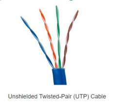
STP (Shielded Twisted Pair): Better noise protection, more expensive, harder to install, uses shielding.

Coaxial Cable: Used for wireless antennas and cable internet; consists of jacket, braid/foil, insulation, and conductor.

4. UTP Cabling
Properties:
Four pairs of color-coded wires, no shielding, relies on cancellation and varied twists to limit crosstalk.
LAN Standards:
TIA/EIA-568 (cable types, lengths, connectors, termination, testing).
IEEE defines electrical performance (Category 3, 5, 5e, 6).
Connectors:
RJ-45 is standard; proper termination is crucial.
Cable Types:
Straight-through: Both ends T568A or T568B; used for host-to-network device.
Crossover: One end T568A, other T568B; used for host-to-host, switch-to-switch, router-to-router (now mostly legacy due to Auto-MDIX).
Rollover: Cisco proprietary; used for console connections.
5. Fiber-Optic Cabling
Properties:
More expensive, ideal for long distances and high bandwidth, immune to EMI/RFI, uses glass fibers and light pulses.
Types:
Single-Mode Fiber (SMF): Small core, uses lasers, long distances.
Multimode Fiber (MMF): Larger core, uses LEDs, shorter distances (up to 550m at 10Gbps), more dispersion.
Usage:
Enterprise Networks - backbone cabling
FTTH (Fiber-to-the-Home) - provides always-on broadband service
long-haul networks - connects countries and cities
submarine cables networks - survives in harsh undersea environments
Connectors:
ST (Straight Tip)
SC (Subscriber Connector)
LC (Lucent Connector)
duplex multimode LC.
Patch Cords:
SC-SC MM
LC-LC SM
ST-LC MM
ST-SC SM.
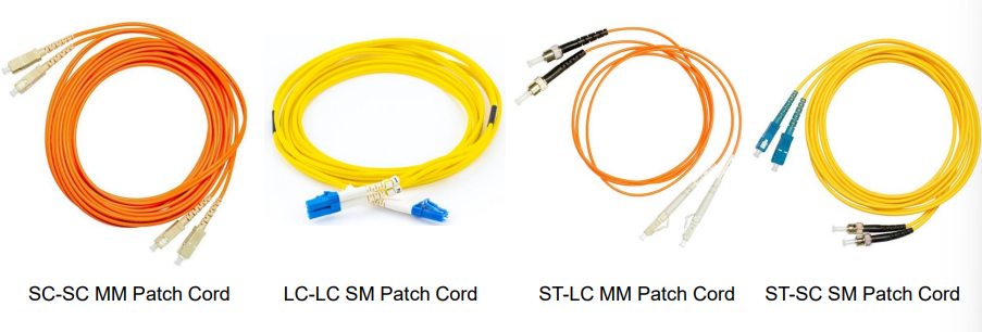
Color Coding:
Yellow for SMF, orange/aqua for MMF.
Comparison with Copper (UTP):
Fiber supports higher bandwidth, longer distances, is immune to EMI/RFI and electrical hazards, but is more expensive and requires more skill to install.
6. Wireless Media
Properties:
Uses electromagnetic signals (radio/microwave), offers mobility, but has limitations (coverage, interference, security, shared medium).
Limitations:
Coverage affected by environment
susceptible to interference
security risks (no physical access needed)
shared bandwidth
Standards:
Wi-Fi (IEEE 802.11) - Wireless LAN (WLAN)
allows you to move freely (mobility)
Bluetooth (IEEE 802.15) - Wireless Personal Area Network (WPAN)
WiMAX (IEEE 802.16) - point-to-multipoint topology
Zigbee (IEEE 802.15.4). - low data-rate, primarily for Internet of Things (IoT) applications
wireless data communications cover both data link and physcial layers
physical layer specifications:
data to radio signal encoding methods
frequency and power transmission
signal reception and decoding requirements
antenna design and construction
Devices:
Wireless Access Point (AP) - concentrate wireless signals from users
connects to the existing copper-based network
Wireless NIC adapters - wireless communications capability to network hosts
Security:
Strong security policies are essential to protect WLANs.
MODULE 5 (Number Systems)
Binary and IPv4 Addresses
Bits
numbering system consists of 1s and 0s
Decimal numbering system
consists of digits 0 through 9
hosts, servers, and network equiptments uses binary addressing to identify each other
addresses is made up to 32 bits
Octets - addresses divided into 4 sections
contains 8 bits or 1 byte
separated by a dot
IPv4 Addresses
routers and computers only understand binary
human understands decimal
Binary Positional Notation
a digit represents different values depending on the position the digit occupies in the sequence of numbers

Binary to Decimal
Step 1: write the simple chart from right to left
128 | 64 | 32 | 16 | 8 | 4 | 2 | 1 |
Step 2: place your binary number under the simple chart
128 | 64 | 32 | 16 | 8 | 4 | 2 | 1 |
1 | 0 | 1 | 0 | 1 | 1 | 0 | 0 |
Step 3: Add the numbers that have 1 under them
128+32+8+4=172
Decimal to Binary
Step 1: Start in the 128 position (highest position), check if the decimal number is greater than the position
186 > 128
12>128
Step 2: if yes, add 1 and subtract the decimal number to the position. If not enter 0 and move to the next position
if yes | |||||||
168 - 128 = 40 | 40 is not greater than 64 | 40 - 32 = 8 | 8 is not greater than 18 | 8 - 8 = 0 | enter 0 in remaining positions | ||
128 | 64 | 32 | 16 | 8 | 4 | 2 | 1 |
1 | 0 | 1 | 0 | 1 | 0 | 0 | 0 |
Hexadecimal Number System
Hexadecimal
converting hexadecimal to decimal is crucial in understanding IPv6
base 16 numbering system
using digits 0 to 9
letters A to F
easier to express a value as a signle hexadecimal than a 4 binary bit
used to represent IPv6 addresses and MAC addresses
IPv6 Addresses
128 bits
every 4 bits represents a single hexa digit
total of 32 hexa values
Hextet - for hexa character group
Conversions
conversion table
A = 10
B = 11
C = 12
D = 13
E = 14
F = 15
DECIMAL TO HEXADECIMAL:
Step 1: Convert the decimal number to 8-bit binary string
Decimal: 15
128 | 64 | 32 | 16 | 8 | 4 | 2 | 1 |
0 | 0 | 0 | 0 | 1 | 1 | 1 | 1 |
Step 2: Split the binary string into 4 groups
8 | 4 | 2 | 1 | 8 | 4 | 2 | 1 | |
0 | 0 | 0 | 0 | 1 | 1 | 1 | 1 |
Step 3: Convert each 4-bit group into hexa by adding each position that has 1 below it
8 | 4 | 2 | 1 |
0 | 0 | 0 | 0 |
0+0+0+0 | = 0 |
8 | 4 | 2 | 1 |
1 | 1 | 1 | 1 |
8+4+2+1 | = 15 | = F (refer to the conversion table) |
Hexadecimal: 0F
HEXADECIMAL TO DECIMAL:
Step 1: Write out each hex and convert any letter to decimal
Hex: CB
C = 12
B = 11
Step 2: Multiply each digit by 16 raised to its positional power, starting from 0 on the right
12 × 16^1 = 192
11 × 1(16^0) = 11
Step 3: Add all the products together
192 + 11 = 203
Decimal: 203
HEXADECIMAL TO BINARY:
Step 1: separate the hex number into individual digits
Hex: CB
C (12) =
B (11) =
Step 2: convert each individual digit into its 4-bit binary using the 8, 4, 2, 1 place value chart
8 | 4 | 2 | 1 | |
12-8 = 4 | 4 - 4 = 0 | |||
C (12) = | 1 | 1 | 0 | 0 |
11 - 8 = 3 | 3 - 2 = 1 | 1 - 1 = 0 | ||
B (11) = | 1 | 0 | 1 | 1 |
Step 3: Combine
11001011
MODULE 6 (Data Link Layer)
Purpose of the Data Link Layer
responsible for communications between end-device NICs (Network Interface Card)
allows upper layer protocols to access the physical layer media
encapsulates layer 3 packets (IPv4 and IPv6) into layer 2 frames
performs error detection
DATA LINK SUBLAYERS
its standards are specific to the type of network (ethernet, WLAN, WPAN, etc.)
2 sublayers:
Logical Link Control (LLC): communicates between the networking software at the upper layers and device hardware at the lower layers.
Media Access Control (MAC): Responsible for data encapsulation and media access control
PROVIDING ACCESS TO MEDIA
packets exchange between nodes may experience numerous data link layers and media transitions
at each hop, a router performs 4 basic layer 2 functions:
accepts a frame from the network medium
de-encapsulates the frame
re-encapsulates the packet into a new frame
forwards the new fram on the medium
DATA LINK LAYER STANDARDS
these protocols are defined by engineering organizations:
Institute for Electrical and Electronic Engineers (IEEE)
International Telecommunications Union (ITU)
International Organizations for Standardization (ISO)
American National Standards Institute (ANSI)
Topologies
arrangement and relationship of the network devices and interconnections between them
Physical and Logical Topologies
Physical Topology: shows physical connections
Logical Topology: identifies the virtual connections
WAN Topologies
Point-to-point: simplest and most common. Consists of a permanent link
Hub and spoke: similar to star topology
central site interconnects branch sites through point-to-point links
Mesh: provides high availability
requires every end system to be connected to every other end system
POINT-TO-POINT WAN TOPOLOGY
physical point-to-point directly connects 2 nodes
nodes may not share with other hosts
all frames on the media can only travel to or from the 2 nodes
node1 ←> network/media ←> node2
LAN Topologies
these are typically interconnected using a star or extended star topology
easy to install, very scalable, and easy to troubleshoot
2 additional topologies:
Bus: all end systems chained together
terminated on each end
Ring: each are connected to its respective neighbors to form a ring
Half and Full Duplex Communication
Half-duplex:
only allows 1 device to send or receive at a time on a shared medium
used on WLANs and legacy bus topologies (with ethernet hubs)
Full-duplex:
allows both devices to simultaneously transmit and receive
ethernet switches operate in full-duplex mode
ACCESS CONTROL METHODS
Contention-based access
all nodes operating in half-duplex
ex. Carrier sense multiple access with collision detection (CSMA/CD) as used on legacy bus-topology ethernet
ex. Carrier sense multiple acces with collision avoidance (CSMA/CA) as used on Wireless LANs
CSMA/CD: only one device send or receives at a time
uses collision detection process to decide when a devicec can send and what happens if multiple devices send at the same time
used by legacy ethernet LANs
(CS)senses to see if any other computer is currently transitting a signal -> (MA)anyone can send whenever it becomes quiet -> (CD) stops transmitting if a collision happens, sends a jam signal, waits a random amount of time, and tries again.
CSMA/CA:
used by IEEE 802.11 WLANS
devices receive a time duration to know how long the medium will be unavailable when a collision happens
Controlled Access
deterministic access
each node has its own time on the medium
used on legacy networks
such as Token Ring and ARCNET
Data Link Frame
The Frame
data is encapsulated by the data link layer with a header and a trailer to form a frame
data link frame parts
header
data
trailer
amount of control information carried with in the frame varies according to access control information and logical topology
Frame Fields
Frame Start and Stop - identifies beginning and end of frame
Addressing - indicates source and destination nodes
Type - indentifies encapsulated layer 3 protocol
Control - flow control services
Data - contains the frame payload
Error Detection - determines transmission errors
Layer 2 Addresses
also referred to as a physical address
contained in the frame head
used only for local delivery
updated by each device
LAN and WAN frames
the logical topology and physcial media determine the data link protocol used:
ethernet - rulebook for wired local networks
uses physcal cables to send data between computers and switches in the same building
802.11 Wireless - official engineering name for Wi-Fi
rulebook for moving data through the air
point-to-point (PPP) - direct digital highway
used to connect exactly 2 devices
High-level data link control (HDLC) - classic cisco-default protocol
used to cleanly package and deliver data
frame-relay - older, cost-efficient technology
allowed multiple businesses to share a single provider network
MODULE 7 (Ethernet Frames)
Ethernet Frames
ETHERNET ENCAPSULATION
operates in both the data link layer and the physical layer
comprises a family of networking technologies
defined in the IEEE 802.2 and 802.3 standards
DATA LINK SUBLAYER
To make things easier to manage in the 802 LAN/MAN standards and ethernet, the Data Link layer is split into 2 smaller sublayers:
LLC Sublayer (Logical Link Control - IEEE 802.2) - places control information inside the frame header
identifies which network layer protocol is being used for the frame
MAC Sublayer (Media Access Control - IEEE 802.3, 802.11, or 802.15) - handles data encapsulation, media access control, and physical layer 2 addressing
MAC SUBLAYER
responsible for data encapsulation and accessing the media
Data encapsulation:
Ethernet Frame - internal layout structure
Addressing - adds souce and destination MACs for NIC-to-NIC delivery on the same LAN
Ethernet Error Detection - uses Frame Check Sequence (FCS) trailer for error detection
Media Access (Traffic control):
Legacy ethernet using a bus topology or hubs, is a shared half-duplex medium
ethernet LANs of today uses switches that operate in full-duplex
ETHERNET FRAME FIELDS
FRAME SIZES:
Standard Ethernet frame size: minimum 64 bytes,, maximum 1518 bytes
Runt Frame / Collision Fragment: under 64 bytes. Automatically dropped (usually collision debris)
Jumbo/baby giant frame: data payload over 1500 bytes (total over 1518 bytes). supported by most fast/gigabit swtiches
Dropping: any frame outside the 64-1518 byte limits is considered invalid and dropped
Ethernet MAC Address
MAC ADDRESS AND HEXADECIMAL
FORMAT:
Structure: 48 bits long, written as 12 hexadecimal digits (6 bytes)
Hex Conversion: 8 bits (1 byte) ranges from binary 00000000 - 11111111 (00 to FF in hex)
leading zeros are required (0A). Hex is shown in documentation with a 0x prefix (e.g., 0×73), a subscript 16 (7316), or an H suffix (73H)
MAC addresses provides a method for device identification at the data link layer of the OSI model
Organizationally Unique Identifier (OUI): assigned to vendors by the IEEE
every MAC must be globally unique
vendors that sell ethernet devices must register with the IEEE to obtain a unique 6 hexadecimal code
consists of 6 hexadecimal vendor OUI code
followed by a 6 hexadecimal vendor-assigned value
FRAME PROCESSING
NIC Filter: A network card checks the Destination MAC of a frame:
No match: drops the frame
match: pulls it into RAM and de-encapsulates it up the OSI layers
NICs also accept frames if the target is a network broadcast or a multicast group they belong to. (PC, routers, printers, and phones all have MACs)
COMMUNICATION TYPES
TYPE | TARGET | DESTINATION MAC FORMAT | SOURCE MAC RULE |
Unicast | one specific device | target’s unique physical MAC | must always be unicast |
Broadcast | everyone on local LAN | all binary 1s FF-FF-FF-FF-FF-FF | a single device |
Multicast | a specific group | starts with 01-00-5E (IPv4) or 33-33 (IPv6) | a single device |
Finding destination MACs:
IPv4: uses ARP (Adress Resolution Protocol)
acts like a public loudspeaker on a local network; it sends a broadcast message to every single device asking, "Who has this IP address, and what is your MAC address?"
IPv6: uses ND (Neighbor Discovery)
replaces this with a much quieter, targeted multicast message that is delivered only to the specific device in question
Router Boundary: routers block broadcasts/multicasts by default
switches flood them out all ports
The MAC Address Table
SWITCH FUNDAMENTALS
Layer 2 Rules: switches make decisions based solely on layer 2 MAC addresses.
they ignore layer 3 protocols
CAM (Content Addressable Memory) Table: the MAC Address table or CAM table maps MACs to physical ports
Boot State: completely empty when powered on
SWITCH LEARNING AND FORWARDING
Learn (Examine the source MAC adrress)
the switch looks at the source mac and the incoming port
New MAC: Adds the MAC and port to the table
Existing MAC: refreshes its 5-minute aging timer
Moved Port: replaces the old record with the new port number
Forward (Find the Destination MAC Address)
Known Unicast: MAC is in the table. sends it out only that one specific port (filtering)
Unknown Unicast: Unicast MAC is not in the table. Floods it out all ports except the incoming one
Broadcast/Multicast: flooded out all ports except the incoming one automatically
FILTERING FRAMES
as a switch receives frames from different devices, it is able to populate its MAC address table
examines the source MAC address of every frame
Switch Speeds and Forwarding Methods
FRAME FORWARDING METHODS ON CISCO SWITCHES
Store-and-forward switching: receives the entire frame and checks the CRC code for errors
drops bad frames and forwards clean ones
Mandatory Quality of Service (QoS): prioritizes traffic (like VoIP over web browsing)
Cut-Through Switching: reads just the Destination MAC at the front, then immediately starts forwarding
no error checking
Fast-forward switching: standard method, lowest latency, sends everything instantly, even if broken
Fragment-Free switching: stores and checks the first 64 bytes (where most collision happens) before forwarding
MEMORY BUFFERING ON SWITCHES
an ethernet switch may use a buffering technique to store frames before forwarding them or when the destination port is busy because of congestion
Port-Based Memory: Frames wait in queues tied to specifc ports
can cause Head-of-Line Blocking
Shared Memory: all frames go into a common pool shared by all ports
deposits all frames into a common memory buffer shared by all switch ports
amount of buffer memory required by a port is dynamically allocated
eliminates line blocking and allows asymmetric switching
DUPLEX AND SPEED SETTINGS
2 of the most basic settings on a switch are the bandwitdth
it’s important that the duplex and bandwidth settings match between the switch port and the connected devices
Full Duplex: both ends of the connection can send and receive simultaneously
two-way talk
gigabit ethernet only operates in full-duplex
Half-Duplex: one side talks at a time (shared media)
only one end of the connection can send at a time
Autonegotiation is an optional function found on most Ethernet switches and NICs
enables 2 devices to automatically negotiate the best speed and duplex capabilities
Duplex Mismatch: performance bug where one side is set to half-duplex and the other to full-duplex
fixed by keeping autonegotiation ON/OFF on both sides
Auto-MDIX: automatically detects the connected cable type (straight-through or crossover)
enabled by default on Cisco IOS 12.2(18(SE) or later
turn back on using command: Switch(config-if)# mdix auto
MODULE 8 (Network Layer)
Network Layer Characteristics
Network layer
provides services to allow end devices to exchange data
IPv4 and IPv6 are the principle network layer communication protocols
makes communication between different networks possible
4 basic operations:
addressing end devices
assigns logical addresses to devices
encapsulation
process of adding protocol information to data
add layer 3 header
routing
determines the best path for packets
de-encapsulation
removes the layer 3 header at the destination
passes the data to the transport layer
moves up the OSI model
IP ENCAPSULATION
IP encapsulates the transport layer segment
segment becomes the payload of the IP packet
segment - PDU of the transport layer
payload - actual data carried inside a packet
IP can use either an IPv4 or IPv6 packet and not impact the layer 4 segment
TCP and UDP work with both IPv4 and IPv6
IP packet will be examined by all layer 3 devices as it traverses the network
routers inspect the packet header
routers check destination IP addresses
traverse - move across a network
this is AI now
The IP addressing does not change from source to destination.
Source and destination IP addresses remain the same during transmission.
Note:
NAT will change addressing, but will be discussed in a later module.
Definition:
NAT (Network Address Translation) – modifies IP addresses between private and public networks.
Characteristics of IP
IP is meant to have low overhead and may be described as:
Connectionless
Best Effort
Media Independent
Definition:
Overhead – additional processing or control information added during communication.
Connectionless
IP is Connectionless
IP does not establish a connection with the destination before sending the packet.
Packets are sent immediately without setup.
Definition:
Connectionless Communication – communication without first establishing a dedicated session.
There is no control information needed (synchronizations, acknowledgments, etc.).
IP does not coordinate transmission before sending data.
Definition:
Synchronization – coordination between devices before communication.
Acknowledgment (ACK) – a confirmation that data was received.
The destination will receive the packet when it arrives, but no pre-notifications are sent by IP.
IP does not notify the receiver beforehand.
If there is a need for connection-oriented traffic, then another protocol will handle this (typically TCP at the transport layer).
TCP handles reliable communication.
Definition:
Connection-Oriented Communication – communication requiring an established connection before transmission.
TCP (Transmission Control Protocol) – reliable transport layer protocol.
Best Effort
IP is Best Effort
IP will not guarantee delivery of the packet.
Packets may be lost during transmission.
Definition:
Best Effort Delivery – a delivery method without guaranteed success.
IP has reduced overhead since there is no mechanism to resend data that is not received.
Less processing improves transmission speed.
IP does not expect acknowledgments.
IP sends packets without waiting for confirmation
IP does not know if the other device is operational or if it received the packet.
IP cannot detect device status or successful reception.
Definition:
Operational – functioning and available for communication.
Media Independent
IP is unreliable
It cannot manage or fix undelivered or corrupt packets.
IP does not repair damaged packets.
Definition:
Corrupt Packet – a packet damaged during transmission.
IP cannot retransmit after an error.
Lost packets are not resent by IP.
Definition:
Retransmission – sending data again after failure.
IP cannot realign out of sequence packets.
IP cannot reorder packets arriving incorrectly.
Definition:
Out-of-Sequence Packets – packets arriving in the wrong order.
IP must rely on other protocols for these functions.
TCP commonly handles reliability.
IP is Media Independent
IP does not concern itself with the type of frame required at the data link layer or the media type at the physical layer.
IP works regardless of the network technology used.
Definition:
Data Link Layer – Layer 2 responsible for framing and MAC addressing.
Physical Layer – Layer 1 responsible for physical transmission.
Frame – the PDU of the data link layer.
IP can be sent over any media type:
copper
fiber
wireless
Definition:
Media Type – the physical method used to transmit signals.
Media Independent (Contd.)
Maximum Transmission Unit (MTU)
The network layer will establish the Maximum Transmission Unit (MTU).
Definition:
MTU (Maximum Transmission Unit) – the largest packet size allowed on a network.
Network layer receives this from control information sent by the data link layer.
Layer 2 informs Layer 3 about size limitations.
The network then establishes the MTU size.
Devices determine the largest allowable transmission size.
Example:
Ethernet MTU = 1500 bytes
Definition:
Byte – 8 bits.
Fragmentation
Fragmentation is when Layer 3 splits the IPv4 packet into smaller units.
Definition:
Fragmentation – dividing packets into smaller pieces to fit MTU limitations.
Fragmenting causes latency.
Extra processing increases delay.
Definition:
Latency – delay in data transmission.
IPv6 does not fragment packets.
Routers do not perform fragmentation in IPv6.
Example: Router goes from Ethernet to a slow WAN with a smaller MTU.
Large packets may not fit the WAN packet size limit.
Definition:
WAN (Wide Area Network) – a network covering large geographic distances.
8.2 IPv4 Packet
IPv4 Packet Header
IPv4 is the primary communication protocol for the network layer.
Widely used for internet communication.
Purposes of the Network Header
It ensures the packet is sent in the correct direction (to the destination).
Routers use destination addresses for forwarding.
It contains information for network layer processing in various fields.
Header fields contain routing and control information.
Definition:
Header Field – a section containing specific protocol information.
The information in the header is used by all Layer 3 devices that handle the packet.
Routers process packet headers while forwarding traffic.
IPv4 Packet Header Fields
Characteristics of the IPv4 Header
It is in binary.
Information is represented using 0s and 1s.
Definition:
Binary – numbering system using only two digits: 0 and 1.
Contains several fields of information.
Each field performs a specific networking function.
Diagram is read from left to right, 4 bytes per line.
Packet diagrams are structured systematically.
The two most important fields are the source and destination.
Identifies sender and receiver IP addresses.
Protocols may have one or more functions.
Protocols can perform multiple communication tasks.
Significant Fields in the IPv4 Header
Version
This will be for v4, as opposed to v6, a 4-bit field =
010001000100
Identifies the IP version used in the packet.
Differentiated Services
Used for QoS: DiffServ – DS field or the older IntServ – ToS or Type of Service.
Prioritizes important traffic.
Definition:
QoS (Quality of Service) – prioritization of network traffic.
DiffServ – Differentiated Services method for QoS.
ToS (Type of Service) – older QoS mechanism.
Header Checksum
Detect corruption in the IPv4 header.
Verifies header integrity.
Definition:
Checksum – a value used to detect transmission errors.
Time to Live (TTL)
Layer 3 hop count.
Each router decreases TTL by 1.
Definition:
Hop – movement from one router to another.
When it becomes zero the router will discard the packet.
Prevents endless routing loops.
Definition:
Routing Loop – packets endlessly circulating between routers.
Protocol
I.D.s next level protocol:
ICMP
TCP
UDP
Definition:
ICMP (Internet Control Message Protocol) – used for diagnostics and error reporting.
UDP (User Datagram Protocol) – fast connectionless transport protocol.
Source IPv4 Address
32-bit source address.
Identifies the sender device.
Destination IPv4 Address
32-bit destination address.
Identifies the receiving device.