Notes
8/27 Assembly Language vs. Machine Language
Assembly - consists of mnemonics
ADD, MOV, SUB, CALL
Machine - a numeric language understood by our computer’s processor
Machine & Assembly Language have 1-to-1 relationship
High-level language vs. Assembly
HLL have 1-to-many relationship w assembly & machine language
ex)
C++ Program:
int y;
int x = (y + 4) * 3;
Assembly:
mov eax, y;  //move y to the eax register
add eax, 4;  // add 4 to Eax register
mov ebx, 3;  //move 3 to EBX
imul ebx;    // multiply eax by ebx
mov x, eax   // mov eax to x
Portability:
HLL can be compiled a wide variety of systems
Assembly languages aren’t portable
Modern examples of processor families:
x86 (Intel/AMD)
ARM family (Apples M series chip, Qualcomm Snapdragon, raspberry pi)
MIPs
PowerPC
Risc-V
Data Representation:
System | Base | Possible Digits |
Binary | 2 | 0, 1 |
Octal | 8 | 0 1 2 3 4 5 6 7 |
Decimal | 10 | 0 1 2 3 4 5 6 7 8 9 |
Hexadecimal | 16 | 0 1 2 3 4 5 6 7 8 9 A B C D E F |
examples)
decimal 123 =
10101 (in binary) = 21 (in decimal)
1 × 2^4 + 0×2³
hexadecimal: 101 = decimal: 257
256 + 0 + 1 = 257
hexadecimal: A(10) B(11) C(12)
2560 + 176 + 12 =
octal: 18
= 16 (decimal)
10101 + 10111 =
integer in memory in C++
int x = 21;
Range → for signed integers, the first bit is for positive + or negative -, so the range is
2 to the 31st to 2 to the 31st - 1
8/29 Signed vs. Unsigned Integers
signed integer → negative or positive
range for unsigned integers:
byte: -128 to 127 -2^7 to 2^7 - 1
word: ________ -2 ^ 15 to 2 ^ 15 - 1
doubleword: ___ -2 ^ 31 to 2 ^ 31 - 1
unsigned integer → always positive (includes 0)
unsigned binary integer: in notebook
byte: 8 bits Range: 0 to 2^0 - 1
word: 16 bits (2 bytes) Range: 2^16 - 1
double word: 32 bits (4 bytes) Range: 2 ^ 32 - 1
quadword: 64 bits (8 bytes)
Large Measurements
kilobyte: 2^10 or ~1,000
megabyte: 2^ 20 or ~1 mil bytes
gigabyte: 2 ^ 30 or ~ 1 billion
terabyte
petabyte
exabyte
Finding 2s Complement:
-23 —— -00010111
Starting Value: 00010111
Step1: Flip the bits: 11101000
Step 2: 11101000 + 00000001 = 11101001
Flip the bits: 11101001 → 00010110
Add One: 00010110 + 1 = 00010111
Integer Arithmetic Operations
handled by the ALU (Arithmetic Logic Unit)
operations performed by ALU update CPU Flags in the EFLAGS register (32 bit register)
carry flag (CF) - set when there is a carry out of the MSB doing unsigned arithmetic
overflow flag (OF) - set when signed arithmetic operation and its too large/small to fit inside destination
sign flag (SF) - set to true if the result of the expression was negative
zero flag (ZF) - set if result is zero
9/3 Flags
Carry Flag: indicates that the result is mathematically incorrect when we interpret the operands as unsigned
Overflow Flag: indicates that the result is mathematically incorrect when we interpret the operands as signed
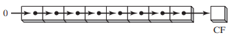
ex 1) in a 4 bit ALU: 1111 + 0001 = 10000
unsigned: 15 + 1 = 0 → incorrect → carry flag is set
signed: -1 + 1 = 0 → correct → overflow flag isn’t set
ex 2) 0111 + 0010 = 1001
unsigned: 7 + 2 = 9 → correct → carry flag isn’t set
signed: 7 + 2 = -7 → incorrect → overflow flag is set
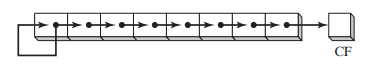
ex 3) 1001 + 1001 = 1[0010]
unsigned: 9 + 9 = 2 → incorrect → carry flag is set
signed: -7 + -7 = 2 → incorrect → overflow flag is set
Character Representation
computers store data as binary, so they use character sets which map binary integers to digital strings
ASCII (American Standard Code for Information Interchange)
7-bit encoding → 128 characters
8th bit would often be used to encode propriety extensions
ANSI Character Set
8-bit encoding (256 characters mappings)
first 128 characters = standard US keyboard
second 128 included chars from international alphabets, currency symbols, other math symbols
Unicode Standard
created to represent all world languages & symbols
UTF-8: used in HTML - shares the same byte values as ASCII
UTF-16: 16-bit encoding - expands the character set, but is still efficient with storage
UTF-32: 32-bit encoding - used in contexts where space isn’t a concern
ASCII Control Characters
control characters: character codes in the range of 0-31
when a program writes these codes to standard outputs, perform a predefined action
Common control characters
ASCII Code (Decimal) | ||
0 | Null Character - string terminator symbol in C/C++ | |
8 | Backspace (moves cursor back one column to the left) | |
10 | Line feed (moves to the next line in output) | |
27 | escape character | |
13 | carriage return | |
9 | horizontal tab |
Boolean Expressions: involves a boolean operator & one or more operands, implies a value of true or false
Boolean Algebra: defines a set of operations on values that are true and false
Boolean operators
NOT - unary operator → one operand
! → programming languages(C++, java, python)
- (bar) → mathematics/logic course
~ → bitwise not in programming (one’s complement)
‘ → common notation Boolean algebra or circuit design
AND - binary → 2 operands
“&&” (logical AND) “&” (bitwise AND)
^ → mathematics/logic
“.” → (dot symbol) Boolean/digital electronics context
A * B or AB
OR - binary → 2 operands
programming: || (logical OR), | (bitwise OR)
“v” → mathematics/logic
“+” → circuit design
NOT operator will reverse a Boolean value
X | -X (bar x) | |
false | true | |
true | false |
AND operator
X | Y | X^Y |
F | F | F |
F | T | F |
T | F | F |
T | T | T |
OR operator
X | Y | XvY |
F | F | F |
F | T | T |
T | F | T |
T | T | T |
Operator Precedence
Expression | Order of Operations | |
-X v Y | NOT first, then OR | |
-(X v Y) | OR first, then NOT | |
X v (Y^Z) | AND first, then OR |
9/8 Basic Microcomputer Design/EAX/CPU Execution Cycle/Pseudocode Process
In the CPU:
registers: high-speed memory locations
system clock: synchronizes CPU with system operations
control unit: coordinates sequencing and execution of instructions
ALU (Arithmetic Logic Unit): Arithmetic & logic operations
Buses: transfer data instructions
most computers are on 64 bit
2^64 which is up to 16 exabytes, or 16 trillion terabytes
32-bit Intel x86 Architecture
2^32 which is up to 4GB addressable memory
8 General Purpose Registers
EAX, EBX, ECX, EDX, EBP, ESP, ESI, EDI
typically used for arithmetic & data movement
data held in this are programmable
Conventional Uses
EAX: holds result of multiplication/division instructions
ECX: CPU will typically hold loop iterators here
ESP: used to address data on the stack
ESI & EDI: used by high-speed memory to transfer instructions
EBP: used to reference function parameters & local variables on the stack
Some registers can be addressed in smaller bit increments
EAX. EBX, ECX, EDX → can be broken down into 16, 8(high) and 8(low)
ESI, EDI, EBP, ESP → can be broken down into 16
IP (Instruction Pointer) → register contains address of the next instructions
Status Registers → EFLAGS (flags, rflags)
contains individual bits to represent different status flags
Segment Registers -
CPU Execution Cycle
Fetch
- retrieve instruction from memory
advance instruction pointer
Decode
analyze the bit pattern of the instruction & determine which operation to execute
Fetch Operands
fetch other operand from register/memory location
may involve calculating the address
Execute
CPU is going to execute the target operate
update status flags
Store Result
store the result in specific destination (memory or register)
Pseudocode Process
loop
fetch next operation
advance instruction pointer (IP)
decode instruction
if memory operand needed → read value from memory and execute instruction
if result is memory operand → write result to memory
9/10 ×86 Processors
32-bit x86 Processors
Modes of operation:
protected mode
virtual
real-address mode
system management mode
Protected Mode:
→ default native state
all instructions & features of the processor are available
programs are given separate memory areas and the processor blocks programs from referencing memory outside that area
Real-Address Mode:
direct access to system memory and hardware devices
mirrors how older 86 processor used to operate
→ one program is running, and we execute one instruction at a time
→ the CPU allows devices to issue an interrupt which will interrupt the normal program flow and execute a different line of instructions
System Management Mode:
provides OS with a way to implement fcns, like power management/system security
typically be customized by manufacturer of computer
customize the processor for a particular set up
MacBook Air v. Desktop
Virtual 8086 Mode (sub-mode of protected mode)
grants ability to run older software designed to run in real-address mode in a safe environment
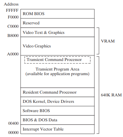
x86 Memory Management
in Real Address Mode an x86 processor can access 1 megabyte of memory in range of 0 to FFFFF
On older 8086 processors (16-bit) we always ran in Real Address Mode
16-bit registers
Engineers had to question: How do we store a 20-bit address into 16-bit register?
Segmentation:
Memory is divided up into 64KB units called segments
Each segment beings at a memory location ending in 0
Because the last digit always ends in 0, referring to a segment the last zero is omitted
to access the specific memory location, provide a 4-bit offset
Protected Mode Memory Management
in protected mode, a program’s linear address space is 4GB,
addresses: 0 to FFFFFFFF
9/12 Segmented Memory Map
Segmented Memory Map
Programs can’t reference a linear address directly
use segment-offset address
16-bit segment value (CS, DS, ES, SS)
16-bit offset value
Ex: 08F1 (segment) : 0100 (offset)
08F1 × 10h = 08F10h
linear address: 09010
Ex: 200A:B608
200A*10h = 200A0 + B608 = 2B6A8h
3 Segments in a Typical Code
Code segment (base address stored CS)
IP register is used for offset (IP - instruction pointer)
IP pointer points to next instruction
Stack segment (base address stored SS register)
normal stack fcn → FIFO
SS register points to the base of stack segment
2 other registers: SP (stack pointer) - points to top of the stack & BP (base-pointer register) - points to current stack frame
What is stored on the stack:
Return addresses
CALL instruction
Near CALL - push current instruction pointer (IP) onto the stack
Far CALL - push IP & CS
RET instruction
pop CS & IP off the stack
→ needs to restore these registers so program can pick where left off
Saved Registers
when return from a procedure, the caller expects registers to remain unchanged
convention is for the callee (fcn that was being called) to start by pushing the registers to the stack, and then restore them when finished
ex
ex:) push AX;
push BX;
...
; do stuff
pop AX;
pop BX;
Function Parameters
(callee’s) fcn parameters pushed onto BEFORE call is made by the caller
BP is going to be used as a reference for where to find parameters on the stack
callee w/ use BP reference
Restore state of CPU after interrupt is issued
interrupt will push registers flag etc. onto stack & then restore the state of the CPU when its finished
Data segment (base address stored DS register)
ES → extra segment
Function Calls
Near CALL will just move the IP register
Far CALL will move both IP and CS
Fcn Call in Assembly
(semi colons are comments-ignored)
maybe ignore:
example_func:
	push bp ; //push base pointer of the caller onto stack
	push registers
	mov sp, bp ;  //set frame pointer to sp
	sub sp, 12 ; //reserve space for local variables - subtracting 					                                       12 from sp
	;...[bp - 2] , [bp - 4] to reference arguments
	pop registers (if necessary)
	pop bp;
myFunc(int a, int b){
int c = a + b;
int d = a + c;
}
my_func:
push bp ;
mov sp, bp ;
; push registers
sub sp, 2 ; 9/15
Fcn Call in Assembly continued
stack grows down in memory
example_func:
push bp		; push caller bp on stack
mov bp, sp	; start a new frame
sub sp, 12	; reserve enough space for 6 local variables

; [bp + 4], [bp + 6] ... referencing arguments
; [bp - 2], [bp - 4] ... referencing locals

mov sp, bp	; discard all local variables
pop bp		; restoring the caller's stack frame
ret		; return IP
int main (){
	myFunc(5.7);
	return o;
}

int myFunc(int a, int b){
	int c = a + b;
	int d = a + c;
	int retVal = myFunc2(d);
	return retVal;
}
int myFunc2(int x){
	int y = 5;
	return y + x;
}
9/19 Stages of Compilation/Optimizations
Compare Instruction: CMP takes 2 arguments & internally calculates (arg1 & arg2), if they’re equal Zero Flag = 1, if arg1 > arg2 the Sign Flag = 0, if arg1 < arg2 Sign flag = 1
Carry Flag would be set to 1 if unsigned borrow occurred
Overflow Flag would be set to 1 to indicate that signed overflow occurred
JGE label
jump to label if ZF = 1
Stages of Compilation
Lexical Analysis - converts program into individual tokens that can be parsed separately
Syntax Analysis - (parsing stage) - insures grammar rules of programming language are followed, (identifies syntax errors)
Semantic Analysis - (type checking) - insures program follows type rules
ex. int a = “string” → error because rule wasn’t followed - semantic violation
Intermediate Code Generation - generates machine-independent IR (intermediate representation)
Optimization - optimizes code based on target system architecture
Assembly
Linking
Optimizations:
Cost analysis: trying to determine highest priority variables and assigning them to registers accordingly
variables that can’t be written to registers will be spilled onto stack
Code Generation: add instructions to push “spilled over” variables onto the stack
will move back into register when used again
Modern Memory usage algorithms
Interference Graph Coloring
start...
init A
init B
use B
init C
use A
init D
use D
use C
end...
Linear Scan “Just in Time”
assign registers based on “Live Intervals” (duration of use)
spill variables used farthest in future onto stack
x86 Protected (32-bit system)
Each register holds 32-bits
Program given linear address space of 4GB
0 to FFFFFFFF
*Note: Segmentation works differently in protected mode than in real address mode
Different ways of representing memory in protected mode
Flat segmentation model
Paging
Flat-Segmentation:
One 32-bit integer is enough to hold the address of an instruction or variable
segment registers → point at segment descriptor tables
CS register → code descriptor table
DS → data descriptor table
SS → stack descriptor table
ES
CS, DS, SS, ES → become segment selectors in protected mode
9/22 Protected Mode
Intel 32-bit protected mode
segment descriptor: 64-bit structure, provides CPU with info about the segment
Descriptors contain:
Base Address (32-bits): linear address where the segment begins
Limit (20 bits): number of bytes in the segment (size)
Type (1-bit): code segment or data segment
privilege level: 00 → highest privilege level (OS, kernel)
11 → lowest privilege level (user)
01 & 10 → intermediary privilege levels (not commonly used)
Descriptor Table: a linear array of 8-byte descriptors
Flat segmentation model → used by x86 32-bit systems
Global Descriptor Table (GDT): contain system-wide descriptors, OS code/data descriptors, user code/data descriptors
In a multi-segment model…
LDT (local descriptor table)
each task gets private descriptor table
Lab: convert HLL into assembly (16-bit real mode), Graph coloring compiler optimizations
entry:
    t0 = const 0            //start of t0 being live
    t1 = const 1            //start of t1 being live
    t2 = le t0, t1           //end of t1 being live, start of t2 live
    cjump t2, base, init        //end of t2 live
base:
    ret t0                // end of t0 being live
init:
    t3 = const 0            //start t3 live
    t4 = const 1            //start t4 live1
    t5 = const 2            //start t5 live1
loop_test:
    t6 = gt (greater than) t5, t0        //start t6 live
    cjump = t6, done, loop_body           //end t6 live
loop_body
    t7 = add t3, t4                //start t7 live, end t3 live,
    t8 = mov t4                    //start t8 live, end t4 live1
    t9 = mov t7                    //end t7 live
    t10 = add t5, const 1            //end t5 live1
    t3 = mov t8                    //end t8 live, start t3 live
    t4 = mov t9                    //start t4 live2
    t5 = mov t10                    //end t3 live, start t5 live
    jmp loop_test                // end t5 live
done:
    ret t4                    //end t4 live2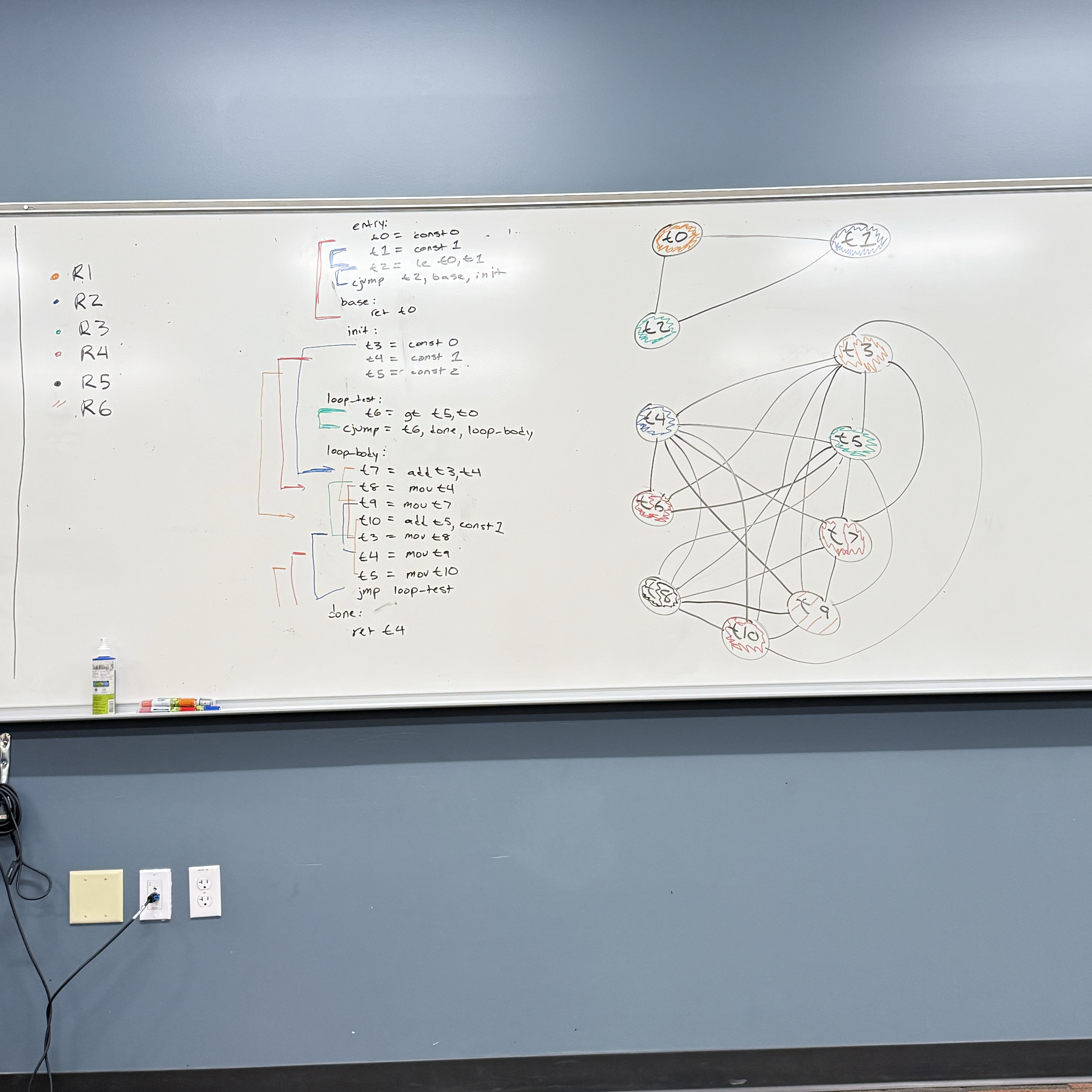
9/24
x86 Components:
Motherboard: circuit board that connects components such as CPU, memory, input/output, devices power supply - connected via the “BUS”, wires etched directly into the board
CPU Socket: different motherboards will have differently shaped CPU sockets
DIMM memory slots
BIOS (Basic input/output system) chips - holds system software info
Connectors for long-term storage devices, CD drive, hard-drive, floppy disk drive, etc.
USB (universal serial bus) connectors
keyboard/mouse ports
PCI (peripheral component interconnect) connectors - sound cards, graphic cards, or other output devices - high speed connection
graphics card/sound card - graphics/sound processor can also be integrated directly into the board
Motherboard Chipset
→ collection processors designed to work with specific motherboard
Can have different priorities:
a laptop or mobile device might prioritize power efficiency
a PC with a dedicated power may prioritize processing speed over power efficiency or thermal efficiency
some may run one task efficiently while others try to accommodate multi-tasking
Types of Memory:
ROM (read-only memory):
permanently burned into the chip (can’t be erased or reprogrammed)
stable, trusted code/data that system will use to start and run
Bootloaders: code that runs on system start-up
Hardware initialization routines: clock/power setup, peripheral discovery
Config info: factory serial, MAC addresses
micro code: internal logic sequences for CPU to run
Note: ROM can’t executed directly must be read and copied to executable part of memory
EROM: Erasable ROM → can be erased and reprogrammed using a UV light → outdated, however…
useful for pre-production development
hobby/education use
cheaper than replacing the component if bug was found after production
DRAM: Dynamic Random Access Memory
“system memory”
volatile memory → data not retained when system loses power
each bit lives within a cell
cells contain a transistor and a capacitor
if capacitor is charged → bit is a 1
if capacitor not charged → bit is a 0
capacitors don’t hold charge for very long (milliseconds) so it must be constantly refreshed
where program data and instructions will be stored while running
SRAM: Static Random Access Memory (CPU Cache)
also volatile (needs power to retain info, but doesn’t need to be constantly refreshed)
faster/easier to access then DRAM
access is deterministic
VRAM: holds video data
dual ported:
1 port to refresh the display
1 port that writes data/updates data that will be displayed
CMOS RAM: system set up information, contains a small battery so contents are retained
Long-term storage
Hard-Drives, SSD, CDs, Floppy Disk, SD Cards, Flash Drive
non-volatile: don’t require power to retain information
typically slower to access data from
When computer loads program
data/instructions are read from non-volatile memory and copied into DRAM/volatile memory
saving data will copy from our volatile (working memory) → non-volatile destination
Input/Output
I/O doesn’t always require direct hardware access
HLL’s standard library functions, not tied to a particular OS or computing system
OS provided API (application programming interface). contains library different high level functions including input/output
BIOS (basic-input-ouput system)
low-level subroutines that communicate directly with the computer hardware
these are typically installed by manufacturer & tailored to specific machine
the OS will communicate with device using BIOS subroutines
Device Drivers
permit the OS to communicate hardware devices and BIOS directly
OS requests to read data → device driver executes code to read data
Concrete Example: play a sound file using system’s audio controller device
OS level: call the OS API, don’t need to worry about what device is installed or non-standard features it may have
BIOS level: need to use a device driver to query the sound card and find out what features it may have
Hardware level: program would need to accommodate different types of devices in my program (or not)
General Purpose OS typically only allow hardware access through device drivers
Microsoft MASM assembler - 32-bit
Assembly Language Program:
DWORD: 32-bots
WORD: 16-bits
BYTE: 8 bits
sum DWORD 0 → storing 32-bits in memory to store the 0
.data         ; start of info to construct our data segment
    sum DWORD 0   ;defined variable sum, DWORD-> size 32-bits
.code
main PROC    ;start of a procedure
    mov eax, 5
    add eax, 6
    mov sum, eax
    INVOKE ExitProcess, 0    ; calls window provided function to end program
main endP
MASM syntax
[ ]: optional
{ } : requires choice from set of options, separated by the or symbol → |
Possible Radix Values:
h : hexadecimal
d : decimal alt: t
q : octal alt: o
b : binary alt: y
Integer Literals
[{+ 1 -}] digits [radix]
26 : assuming positive and decimal (base 10)
26h : assuming positive and interpret as hexadecimal
-26 : assuming decimal and negative
+1101b : positive, interpret as binary
MASM allows arithmetic operations
( ) parenthesis 1
+,- unary plus/minus 2
*, / multiply/divide 3
MOD modulus 3
+,- add/subtract 4
-(3 + 4) * (6-1)
25 mod 3
Characters Literal: single quotes or double quotes around a single character
‘A’ → asking value for uppercase A
“b” → asking value for lowercase b
String Literals value a similar convention: sequence of characters enclosed in single or double quotation marks
Reserved words:
instruction mnemonics MOV, ADD, …
Register names EAX, BP, …
Directives .data, .code, …
operators +,-, MOD,…
9/29 MASM Assembler
More on MASM Assembler
Identifiers: 1 - 247 char length not case sensitive
First char must be: a-z, A-Z, _, $, ( ), @, ?
Subsequent chars same as above or 0-9
reserved words may not be used
ex.) valid - lineCount, LINECOUNT, _LC
ex.) invalid - 6lineCount, 4L, 014
Directives: Commands recognized by the assembler
not executed at runtime
defines procedures, variables, or Macros
not case sensitive .data .DATA .Data - all valid
assemblers that target the same family of processors will recognize the same instructions but may recognize a different set of directives
.data - defines start of data segment - contains all variables defined
.code - defines code segment’s start - contains program instructions
.stack - size defines the size of runtime stack
.stack 100h will allocate 100 hex (256 decimal) bytes of memory
Instructions: statements translated by the assembler into executable machine language bytes - loaded/executed by machine at runtime
Contains:
1. Label (optional) [label:] mnumonic [operands][;comment]
2. mnumonic (required)
3. opperands (typically required)
4. comment (optional)
Label: identifier acting as a marker for instruction or data represents memory address of what follows
data label: implies mem address of variable following
ex) count DWORD 100 count is a label representing a 32 bit variable - it holds the mem address of the start of these 32 bits
array DWORD 1024 array references the start of the first
DWORD 4096 item in memory (1024) and can be indexed to reference the second (4096)
code label: must end with a colon - used as a target location for jump instructions
ex) target: (doesn’t have to be on its own line)
mov ax, bx
:
jmp target
labels may be repeated if not in the same PROC scope
Instruction mnumonic: identifies an instruction
mov, jmp, inc, …
operand: value used for input or output to an instruction integer literals, registers, variable identifiers
ex.)
INC Ax takes one operand
STC no operand (sets carry flag)
MOV Ax, Bx two operands
MUL Ax, Bx, 5 2 or 3 operands
Comments: begin with semi colon for line comments. block comments begin with key word COMMENT and user specified symbol & end with same symbol
ex.) COMMENT! COMMENT*
NOP no opperation instruction
one byte of memory performs no actions
used to align instructions to certain memory locations
.386        //directive says its a 32 bit program registers and addresses
.model flat, std call         //flat segmentation mem model use std windows service call system
.stack 4096
ExitProcess PROTO, dwExitCode: DWORD //defines prototype for windows service func exit proceses
.code
main PROC
mov eax, 5
add eax, 6
INVOKE ExitProcess, 0 //0 means exited with success
main ENDP //ends procedure
END main //defines end of code section takes a label for program entry point
10/3-10/6 Assembling, Linking, & Executing Programs
Source code written in assembly language, cant execute directly on machine
First we must run through an assembler → produce our object file containing machine language
Object file passed through linker → executable file
Assembly Link Cycle Steps
Write our assembly code in text
Assembler translates into machine code optionally produce a listing file
Take system call code from link library and copy that into our obj
OS Loader loads our machine code into memory and updates IP to look at first instruction
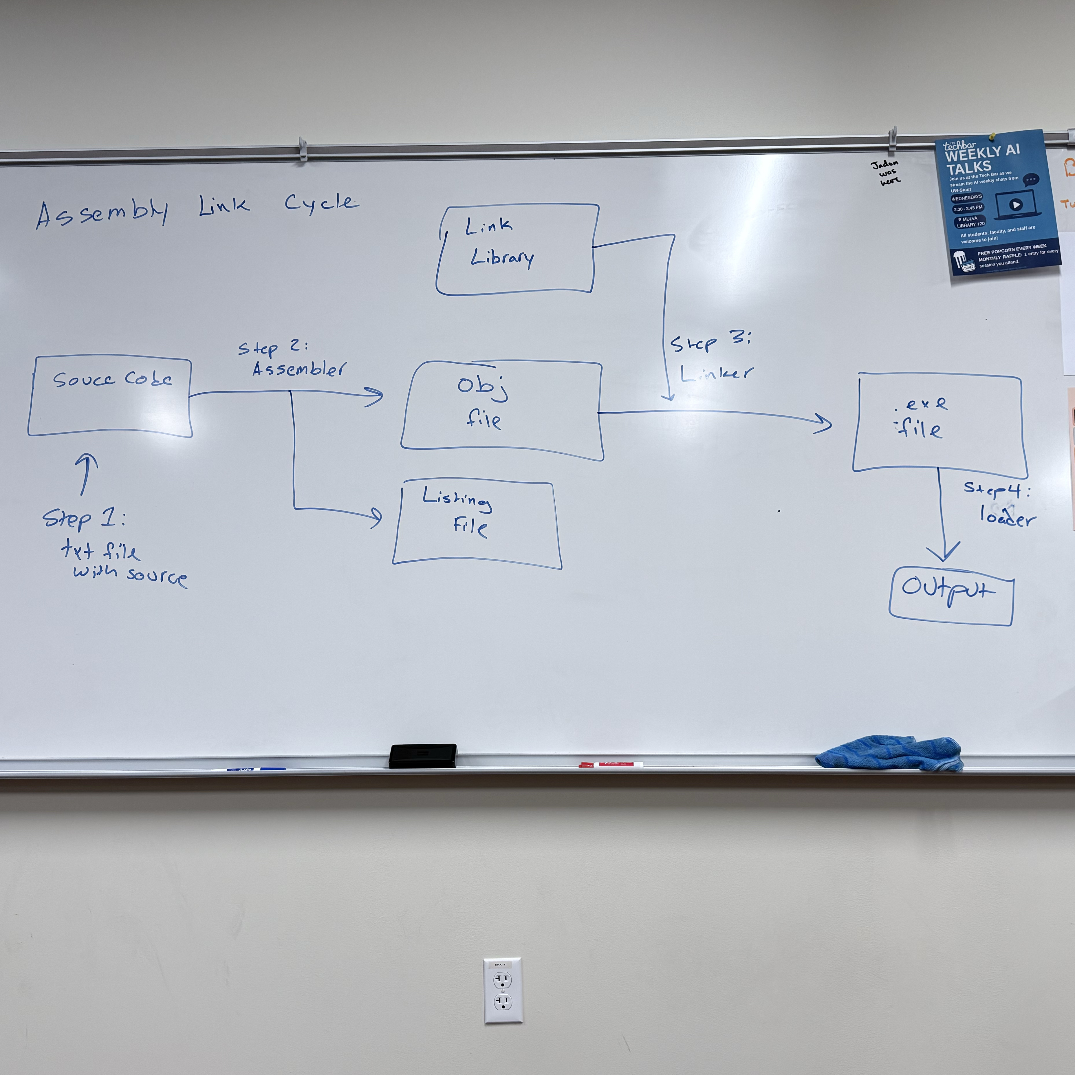
Listing Files: contains readable copy of our code suitable for printing
line numbers
offset addresses
translated machine code
symbol table
Data Definition Statement:
[name] directive initializer [,initializer]….
count DWORD 12345
name must follow identifier rules
BYTE, SBYTE, WORD, SWORD, DWORD, SDWORD, QWORD, SQWORD, FWORD
Legacy TASM directives: DB → 8-bit, DW → 16-bit, DD → 32-bit, DQ → 64-bit
Initializer:
most include at least one initializer (can be 0)
“?” can be used to leave a a variable uninitialized
can be an integer constant or expression → must match variable type (BYTE, WORD)
ex.
value1 BYTE ‘A’ ; char constant
value2 BYTE 0 ; least significant unsigned byte
value3 BYTE 255 ; most significant unsigned byte
value4 SBYTE -127 ; least significant signed byte
value5 SBYTE +127 ; most significant signed byte
val1 DB 255 ; unsigned byte
val1 DB -128 ; signed byte
When multiple initializers are used, the label represents the offset of the first value
list BYTE 10,20,30,40
Not all initializers require a label
list BYTE 10,20,30,40
BYTE 50,60,70,80
BYTE 90,100,110,120
list BYTE ‘A’, 10, 42h, 01010110b
When we use multiple initializers, we can mix char/int constant or the radix
Defining Strings
greeting BYTE "Hello World", 0 //null terminated stringeach char will take up a byte of memory
strings break the “comma separated initializer” rule
→ an equivalent definition would be:
→ greeting BYTE ‘H’, ‘e’, ‘l’, ‘l’, ‘o’, …, O
How data is stored in intel architecture
Store 12345678h at offset 0000
Intel stores data using little endian ordering:
→ least significant byte is stored first
Big endian ordering:
→ stores the bytes in order
Why Intel uses little endian
→ more efficient operation
10/6 Exam 1 Topics
Conversions between binary, decimal, octal, hexadecimal
addition in different number representations
hardware components: CPU, motherboard, RAM, ALU, etc.
Registers → how they’re used
special registers: sp, bp, ax, cs, ds, ss
Labs:
Duh Lab
interpret 8086-like assembly code & trace through the stack
generate small examples of 8086-like assembly code
Real-Address Mode memory organization
how the offset address is calculated
Procedure parameter passing, local variables on the stack, prologue/epilogue
10/8 Continuing with MASM assembler syntax
Defining a string over multiple lines
greeting BYTE “Hello, welcome to my”
BYTE “program.”, 0dh, 0ah
BYTE “Please enter your”
BYTE “name:” , 0dh, 0ah, 0
0Ah and 0Dh represent end of line characters
0Dh: Carriage Return, return the cursor to the starting position on the current line
0Ah: Line Feed, advance the cursor to the next line
The line continuation character (\) will combine two lines of source code into 1
greeting1 \
BYTE “Hello, welcome to my \
program.”, 0dh, 0ah, 0
DUP Operator: allocate storage for multiple data items
BYTE 20 DUP(0) ; → reserves 20 bytes of memory, each containing zero
20 is the counter, number of times I’m reserving the amount of space indicated by size directive
The 0 in DUP(0) is the thing I’m initializing to
BYTE 20 DUP (?) ; → 20 uninitialized (b/c of ?) bytes
BYTE 4 DUP(“HI”) ; → 8 bytes → HIHIHIHI
BYTE 8 DUP(“Hello”) ; → 40 bytes
Symbolic Constants: Associate an identifier with an integer expression or text - assembler substitute the symbol with its associated value when assembling source code
Equal sign directive can be used to associate a symbol with a value
COUNT = 100
:
; later in program
mov eax, COUNT
Assembler will sub count w/ its value
mov eax, 500
Symbols versus Variables
symbols don’t take up memory in our assembled program, values during runtime
variables do take up memory space, value can change during runtime
Why symbols?
readability - easier to read than literal values
flexibility - if symbol occurs multiple times, we only need to change value in one place
Common uses of symbols:
keyboard definitions
Esc_key = 27
mov al, Esc_key ; very readable
mov al, 27 ; not readable - difficult to interpret
In conjunction w/ DUP
array dword COUNT DUP(0)
→ reserve 4 bytes * COUNT, initialize each 4 byte block to 0
Current Location Counter: represented by $
selfptr DWORD $
can be used to calculate the size of an array
list BYTE 10, 20, 30, 40
ListSize = ($ - list)
greeting BYTE “Hello World, I am a string”, 0
greeting_len = ($ - greeting)
list BYTE 10, 20, 30, 40
greeting BYTE “Hello”, 0
listSize = ($ - list) ; Too large
When we use current location counter to calculate size of a list _
10/15 Continuing with MASM
Data Transfer Instruction - instruction that are going to copy data from a source operand to a destination operand
HLL compilers often have strict type checking
Assemblers don’t typically give us type checking features → its up to us to keep track of how we are storing/managing data
x86 Instruction Operands
[label: ] mnemonic [operands] [j comment]
Instructions can have zero, one, two or three operands, so [operands] expands to:
→ nothing ex. set carry flag
→ [destination] ex. INC AX
→ [destination], [source] ex. MOV AX, BX ADD AX, BX
Three Operand Types
Immediate: uses a numeric or character literal
Register: uses a named register
Memory: reference a memory location (directly or indirectly)
Direct Memory Operand: refer to a specific memory offset within the data segment
.data
var BYTE 27h → the label var refers to the offset of a location in the data segment that contains the value 27h
Provide a data label as a memory operand to an instruction will dereference is
ex. mov al, var
al → register operand & var → direct memory operand
This instruction takes value at offset of var label and copies it into the lower 8 bits of the AX register
Brackets
Programmers will often use brackets to indicate they are dereferencing a memory offset
ex. mov al, [var] → logically equivalent to mov al, var
→ done for readability
→ ignored by MASM, but are helpful for readability to denote dereferencing a memory location rather than storing offset
MOV Instruction
MOV dest, source
Rules:
both operands must be the same size
both operands cannot be memory operands
instruction pointer register cannot be the destination operand
MOV reg, reg ex. MOV AX, BX
MOV mem, reg ex. MOV [var], AX
MOV reg, mem ex. MOV AX, [var]
MOV mem, imm ex. MOV [var], 5
MOV reg, imm ex. MOV AX, 5
Not right: MOV 5, AX
Not right: [var], [var2]
Since we can’t directly copy from one memory location to another, we must use a register as an intermediary location
copy data at offset var into offset var2
MOV AX, [var]
MOV [var2], AX
Indirect Memory Operand
.data
array BYTE 11h, 22h, 33h, 44h
mov al, [array] ; mov 11h into al register
mov al, [array + 1] ; indirectly access second value
mov al, [array + 2] ; indirectly access the third value, store 33h into al register
*brackets on all above statements → if we did mov al, array + 2, its logically equivalent to mov al, [array + 2], but mov al, array + 2 looks like you’re adding 2 to the offset and moving it to the al, the brackets make it more clear
Overlapping Values
.data
myByte BYTE 78h
myWord WORD 1234h
myDWord DWORD 12345678h
.code
1. mov eax, 0
2. mov al, 78
3. mov ax, myWord
4. mov eax, myDWord
5. mov ax, 0
6. mov ah, 2
7. mov ax, 5
0000000
00000078
00001234
12345678
12340000
12340200
12340005
10/17
Addition & Subtraction
INC/DEC: Add 1 or decrement 1 from operand
INC register/memory loc
DEC register/memory loc
update EFLAGS: sign flag, overflow flag, zero flag, based on value stored in destination operand
instructions don’t update carry flag
ADD Instruction
ADD dest, source
same rules as MOV instruction (IP not dest, cant add mem loc to mem loc, etc.)
update EFLAGS: sign flag, overflow flag, zero flag, carry flag
Ex. .data
var1 DWORD 10000h
var2 DWORD 20000h
.code
mov eax, var1 ; EAX = 10000h
mov eax, var2 ; EAX = 30000h
SUB Instruction
SUB dest, source
same rules as ADD, MOV, updates same flags based on value put in destination
Ex. C++
result = -x + (y - z)
Assembly Translation
.data
result SDWORD ?
x SDWORD 5
y SDWORD 15
z SDWORD 10
.code
mov eax, x
neg eax ; holds -5
mov ebx, y
sub ebx , z
add eax, ebx
mov result, eax
OFFSET Operator
→ return the offset of a variable (label) from the start of its enclosing segment
Data Segment
.data
val1 BYTE ?
val2 WORD ?
val3 DWORD ?
val4 DWORD ?
Assume DS starts at offset 404000h
mov esi , OFFSET val1 ; 404000h (offset of val)
mov esi , OFFSET val2 ; 404001h (word)
mov esi , OFFSET val3 ; 404003h (dword)
mov esi , OFFSET val 4 ; 404007h (dword)
mov esi, OFFSET myArray + 4; move into the esi register offset of the 5th element from array
Define Program
.data
myArray WORD 1,2,3,4,5
.code
mov esi, OFFSET myArray + 4
mov an offset into another memory location
→ essentially functions like a pointer
.data
myArray WORD 1,2,3,4,5
p DWORD ?
.code
mov esi OFFSET myArray
mov p, esi
PTR Operator
used to override the declared size of an operand
necessary when size attributes are different than what assembler assumes
.data
var DWORD 12345678h
.code
mov ax, var ; error, size mismatch
.code
mov ax, WORD PTR var (stores 5678 in ax)
mov ax, BYTE PTR var (stores 78)
10/22 Align directive, LENGTHOF operator, TYPE operator
.data
wordList WORD 8296h, 3957h
.code
mov eax, DWORD PTR wordList
ALIGN Directive
syntax: ALIGN bound ; bound can be 1, 2, 4, 8, 16
if the bound is 1 → align next var on 1-byte boundary (default)
if the bound is 2 → next var aligned on even numbered boundary
if the bound is 4 → align on address that is a multiple of 4
Assembler places empty bytes before the next variable to fix the alignment
What’s the point? - CPU can process data more efficiently at an even-numbered address
Demonstration:
byteVal BYTE ? ; 00406350h
ALIGN2
wordVal WORD ? ; 00406352h ← jump to next even numbered address
byteVal2 BYTE ? ; 00406354h ←
ALIGN 4
dVal DWORD ? ; 00406358h ←
LENGTHOF Operator : count the number of elements in an array, defined by values appearing on the same line
.data
byte1 BYTE 10,20,30
array1 WORD 30 DUP(?), 0, 0
array2 DWORD 1, 2, 3, 4
string1 BYTE “12345678”, 0
—- —- —- —- —- —- —- —- —-
LENGTHOF byte1 → 3
LENGTHOF array1 → 30 + 2 → 32
LENGTHOF array2 → 4
LENGTHOF string1 → 9
—- —- —- —- —- —- —- —- —- —-
SIZEOF operator: return LENGTHOF * number of bytes of a single element of a variable
SIZEOF byte1 → 3
SIZEOF array1 → 64
SIZEOF array2 → 16
SIZEOF string1 → 9
—- —- —- —- —- —- —-- —- —- —- —-
TYPE operator: return the size of a single element in a variable
TYPE byte1 → 1 (bytes)
TYPE array1 → 2 (bytes)
TYPE array2 → 4 (bytes)
TYPE string1 → 1 (byte)
—- —- —- —- —- —- —- —- —- —- —- —-
offset operator returns the distance of a variable from the beginning of its enclosing segment
.data
val1 BYTE ?
val2 WORD ?
val3 DWORD ?
val4 DWORD ?
Assume .data segment starts at offset 00404000h
mov esi, OFFSET val1
In 32-bit flat segmentation model
mov esi, OFFSET val1; ESI = 00404000h + 0
mov esi, OFFSET val2; ESI = 00404000h + 1
mov esi, OFFSET val3; ESI = 00404000h + 3
10/24
Indirect Addressing → uses a register as a pointer
An indirect operand holds an address of a variable, usually an array or string, and can be dereferenced like a pointer
.data
val1 BYTE 10h, 20h, 30h
.code
mov esi, OFFSET val1
mov al, [esi] ; dereference ESI (AL ← 10h)
In protected 32-bit mode: can use any general 32-bit register as an indirect operand, surrounded by brackets to dereference
EAX, EBX, ECX, EDX, ESI, EDI, EBP, ESP,
EBP, ESP could cause issues
If the destination is an indirect operand, the source value gets placed at the location pointed to by the register
mov [esi], bl → value that was in the bl register will get placed at the address that esi points to
if size of operand is ambiguous, use PTR operator
inc [esi] ; error, assembler doesn’t know size of data type pointed to by ESI
inc BYTE PTR [esi]
inc WORD PTR [esi]
Stepping through arrays
.data
array BYTE 10h, 20h, 30h
.code
mov esi, OFFSET array
mov al, [esi] ; AL ← 10h
inc esi ; increment the value in esi by one (look 1 byte ahead)
mov al; [esi] ; AL ← 20h
inc esi
mov al, [esi] ; AL ← 30h
What about an array with 16-bit values?
.data
array WORD 1000h, 2000h, 3000h
.code
mov esi, OFFSET array
mov ax, [esi] ; AX ← 1000h
add esi, 2 ; advance pointer to next WORD
mov ax, [esi] ; AX ← 2000h
add esi, 2
mov ax, [esi] ; AX ← 3000h
Stepping Through Arrays
.data DWORD
array DWORD 10000000h, 20000000h, 30000000h
.code
mov esi, OFFSET array
mov eax, [esi] ; eax ← 1000000h
add esi, 4
mov eax, [esi] ; eax ← 20000000h
Indexed Operands: adds a constant to an address to generate an effective address
any general-purpose register may be used as an index register
MASM allows for 2 formats
constant [reg] or [constant + reg]
arrayB [esi] ←→ [arrayB + esi]
.data
array BYTE 10h, 20h, 30h
.code
mov esi, 0 ; esi represents index we’re trying to access, initialize to 0 to get first element
mov al, array [esi] ; al ← 10h, accessing element at offset of 0 form the data label array
.data
array DWORD 1000h, 2000h, 3000h
.code
mov esi, OFFSET array
mov ax, [esi] ; AX ← 1000h
mov ax, [esi + 4] ; AX ← 2000h
10/27
TYPEDEF Operator: allows for user-defined types which we can use when defining variables
Ex. define “PBYTE” which would be a ptr to 8-bit data
PBYTE TYPEDEF PTR BYTE
.data
array BYTE 10h, 20h, 30h, 40h
ptr PBYTE array ; ptr PTR BYTE array
.code
mov esi, ptr
mov al, [esi] ; 10h
JMP and Loop Instructions
normally, CPU loads and executes instruction sequentially
using conditional statements we can change the flow of execution
implement it statements and loops
JMP Instruction: performs a non-conditional jump
takes a destination operand, and jumps to that offset
Syntax: JMP Destination ; destination would be a code label, which is translated into an offset by the assembler
When a jump is performed - destination address is loaded into the instruction pointer
Ex. Endless loop
loop_start
:
JMP loop_start
Loop Instruction: repeats statements a specific number of times & automatically the ECX as a counter
Loop Instruction has 2 steps
decrement the ECX register
check if ECX == 0
If ECX is 0, then we break out of loop
If CX ≠ 0 then we are going to jump destination label (repeat statements)
Ex.
mov ax, 0
mov ecx, 5
L1:
inc ax
loop L1
Note: the destination offset must be -128 to +127
→ if the JMP is too far, MASM should give an error
Ex. continually decrement from ecx of FFFFFFFF until 0,
Common Error: be careful not to initialize the ecx counter to 0
mov ax, 0
mov ecx, 0
L1:
inc ax
loop L1
Ex. loop never stop running
mov ax, 0
mov ecx, 5
L1:
inc ax
inc ecx
loop L1
Ex. will never get to 0, first run: ecx → 5, second run: ecx → 3, third run: ecx→ 1, fourth run: ecx → FFFF FFFFh
mov ax, 0
mov ecx, 5
L1:
inc ax
dec ecx
loop L1
.data
count DWORD ?
.code
mov ecx, 100
start:
: //if we need another→ ecx, but need to restore later
mov count ecx ; save ecx counter to restore later
mov ecx, 30 ; move different value into ecx
:
mov ecx, count ; restore the counter into the ecx register
loop start
Nested Loops:
.data
count DWORD ?
.code
mov ecx, 100
L1: outer loop
mov count, ecx; saving the counter for my outer loop, before executing inner
mov ecx, 20 ; loading the counter for inner loop
L2: inner loop
: ; executing inner loop
loop L2
mov ecx, count
loop L1
ASM program template:
; Program template (Template.asm)
.386
.model flat,stdcall
.stack 4096
ExitProcess PROTO, dwExitCode:DWORD
.data
; declare variables here
.code
main PROC
; write your code here
INVOKE ExitProcess,0
main ENDP
END main
10/31 Movzx & Movsx Instructions/Stack
Movzx Instruction: move with zero extend
should only be used with unsigned integers
MOVZX 32 reg, 8reg/16reg
MOVZX 16reg, 8reg
MOVZX 32 reg, 16 imm/8imm
Example:
.data
var1 BYTE 74h;
.code
mov ax, var1
movzx bx, al ; moving a value that’s in a 16 bit register into a 32 bit register
Movsx: move with sign extend → sign extends a value, use with signed integers
Example:
mov al, F4h
movsx bx, al
Stack Operations (32-bit)
Review: array in memory that is maintained by the CPU
return addresses, local variables, procedure parameters, other values use by a procedure/routine
PUSH Instruction: push value onto stack, and decrements the ESP by the size of the operand
PUSH reg32/imm32/mem32 ; decrement the ESP by 4
PUSH reg16/mem16 ; decrement the ESP by 2
POP: pop a value off the stack into the destination operand and increment the ESP accordingly
POP reg32/mem32
POP reg16/mem16
PUSHFD and POPFD
push the 32-bit EFLAGS to the stack, and restore the EFLAGS register by popping from the stack
Example:
pushfd ; save flags register
:
; do some stuff
:
popfd ; restore the flags register
PUSHAD, POPAD
push general purpose registers to stack
→ in order: EAX, ECX, EDX, EBX, ESP(before instruction was executed), EBP, ESI, EDI
POPAD: restore the registers by popping in reverse order
→ in 16-bit mode we use PUSHA & POPA
Useful when we want to use registers in a procedure, but want to preserve calling procedures data
if using pushAD or pushFD, make sure that popAD/popFD get executed before leaving procedure
Example:
my_proc PROC
pushAD
:
mov eax, val1
mov ebx, val2
mov ecx, val3
:
popAD
Bad Example: be careful → if our procedure returns one or more values in a register, we shouldn’t use pushAD or popAD
getVal PROC
pushAD
:
mov eax, returnVal
:
popAD ; overwrite my returnVal
getVal ENDP
Example Program: Reverse a string using stack operations
.data
string BYTE “String to Reverse” , 0
stringSize ($ - string - 1) ; $ takes current offset - offset of string - 1
.code
main PROC
mov ecx, stringSize ; counter
mov esi, 0 ; index
L1:
mov zx eax, string[esi]
push eax ; push char to the stack
inc esi ; increase index to look at next char
loop L1
mov ecx, stringSize
mov esi, 0
L2:
pop eax
mov string[esi], al
inc esi
loop L2
11/3
Defining and Using Procedures (32-bit)
Procedure: a named block of assembly statements that perform some action and optionally return a value (similar to a function/method in a HLL)
Declared using a PROC and ENDP directives. Must also provide an identifier for the procedure
main PROC
; statements
ret
main ENDP
CALL and RET instructions
CALL procName: push the return address on the stack and copy the called procedures address into the instruction pointer (EIP)
RET : pop the return address off the stack and into the EIP (allow us to pick up where we left off in the calling procedure)
Passing Register Arguments to a Procedure
.data
sum DWORD ?
.code
mov eax, 1000h ; argument 1 into eax
mov ebx, 2000h ; arg2 in ebx
mov ecx, 3000h ; arg 3 in ecx
call sumOf ; sumOf takes three arguments in the eax, ebx, ecx & returns sum in eax
mov sum, eax
Documenting Procedures:
Best Practice:
description of what it does
list of parameters, and any requirements they may have
values returned by the procedure
special requirements
; sumOf
; Description: calculates the sum of 3 32-bit integers
; Receives: EAX, EBX, ECX contain the three integers: May be signed or unsigned
; Returns: EAX = sum
sumOf PROC
add eax, ebx
add eax, ecx
ret
sumOf ENDP
Labels in Procedures
by default, labels are only within the scope of the procedure they’re defined in
can affect jump instructions
a global label can be defined using “::”
label::
generally bad practice, because it can lead to issues where the runtime stack gets corrupted
;ArraySum
;calculate the sum of an array of 32-bit integers
;Receive: ECX will contain the number of elements (size), ESI will contain the offset of the array
;Returns: EAX = sum of elements in array
ArraySum PROC
mov eax, 0
L1:
add eax, [esi]
add esi, TYPE DWORD ;(4)
loop L1
ret
ArraySum ENDP
Saving and Restoring Registers
when possible, we want to ensure that our procedures don’t overwrite registers that the caller may have been using
ArraySum PROC
    push ecx
    push  esi
    :
    pop esi
    pop ecx
    ret
ArraySum ENDP
The Uses Operator lets us list registers our procedure will use and the assembler will handle saving/restoring them
ArraySum PROC USES ecx, esi
    mov eax, 0
L1:
    add eax, [esi]
    add esi, TYPE DWORD
    loop L1
    ret
ArraySum ENDP
Linking to an external library
Link Library: file that contains preassembled procedures
To call a link library procedure we would first need to use the PROTO directive to identify it
WriteString protoThen we would call the procedure somewhere in our program
call WriteString
When assembled, the offset of the writestring procedure in my call instruction will be left blank
During the linking phase, it will fill in offset for writestring
—> if writestring isn’t defined, it will give a linking error
11/5 Conditional Processing
Boolean and compare instructions
AND Instruction: perform a boolean (bitwise) AND operation, and it will place the result in the provided destination operand
AND dest, source
AND res, reg
AND reg, mem
AND reg, imm
AND mem, reg
AND mem, imm
Compares operands bit by bit, for each matching pair of bit, if both are a 1 —> resulting bit will be a 1, but if either is a 0 → the resulting bit will be a 0
x | y | x^y |
0 | 0 | 0 |
0 | 1 | 0 |
1 | 0 | 0 |
1 | 1 | 1 |
The AND is useful for clearing certain bits, while leaving others unchanged (masking)
On lab 6, we saw that certain bits in memory are flags to track system settings
Suppose the following 4 bits determine the keyboard status
1 | 1 | 0 | 1 |
caps lock on | num lock on | space bar not pressed | esc key pressed |
If I wanted to turn caps lock and num lock, but preserve other status flags I could use an AND operation
1 | 1 | 0 | 1 | |
AND | 0 | 0 | 1 | 1 |
0 | 0 | 0 | 1 |
mask first 2 bits (00) and preserve last two bits (01)
Convert ASCII chars to uppercase comparing ASCII codes for ‘A’ and ‘a’
(‘a’) 61h = 0 1 1 0 0 0 0 1
(‘A’) 41h = 0 1 0 0 0 0 0 1
Codes are equivalent except for difference in 5th bit - true for all alphabetic ASCII chars
.data
    string BYTE "abcde", 0
.code
    mov ecx, LENGTHOF string - 1
    mov esi, OFFSET string
L1:
    and BYTEPTR [esi], 1 1 0 1 1 1 1 1 b ; clear bit 5
    inc esi
    loop L1

; 'a' : 0110 0001
;       1101 1111
; Result:0100 0001 - uppercase A
Flags → AND always clears the carry and overflow flags, modifies sign and zero flag based on destination operand
OR Instruction: perform a boolean OR expression between each pair of bits
OR dest, source
For each matching pair, if either is a 1 then the resulting bit is a 1
x | y | x v y |
0 | 0 | 0 |
0 | 1 | 1 |
1 | 0 | 1 |
1 | 1 | 1 |
useful for setting bits, while leaving others unchanged
mov al, 1110 0111
 or al, 0000 1100; set bits 2 & 3, AL = 11101111
XOR Instruction: performs exclusive OR operation
XOR dest, source
For each matching bit pair: if both bits are the same → 0, if bits are different → 1
x | y | x + y | (x + y) + y = x |
0 | 0 | 0 | 0 |
0 | 1 | 1 | 0 |
1 | 0 | 1 | 1 |
1 | 1 | 0 | 1 |
NOT Instruction: invert all the bits in an operand (one’s complement)
NOT reg
NOT mem
mov al, 00001111b
NOT al        ; AL = 11110000
NOT instruction doesn’t set any flags
TEST Instruction: performs an implied AND instruction
→ sets sign, zero flags
→ doesn’t modify the operands
Useful for determining if bits are set without changing operands values
Ex. test if bits 0 or 3 are set
test al, 00001001b; test bits 0 & 3
zero flag will be set if tested bits are clear
00100101 ← input (al)
00001001 ← test value
00000001 ,_ result is a non-zero value, zero flag = 0
00100100 ← input
00001001 ← test value
00000000 ← result is 0, zero flag = 1
CMP Instruction: performs an implied subtraction instruction operation
→ use to compare two integers
sets flags, but it won’t modify operands
CMP dest, source
dest < source ZF = 0, CF = 1
dest > source ZF = 0, CF = 0
dest == source ZF = 1, CF = 0
when comparing sign operands, have to look at sign and overflow flags
dest < source → SF ≠ OF
dest > source → SF = OF
dest == source → ZF = 1
doesn’t know if its signed or unsigned
CMP 1, -1
0001 +
CMP is useful paired with conditional jump statements to mirror if statement logic
Setting and clearing individual CPU flags
set zero flag ex.
test al, 0 ; set zero flag
1 1 1 1 1 1 1 1
0 0 0 0 0 0 0 0 =
0 0 0 0 0 0 0 0
and al, 0 ; set zero flag, modifies the operand
clear zero flag ex.
or al, 1 ; clear the zero flag
1 0 1 0 1 1 0 1
0 0 0 0 0 0 0 1 ← at least one bit would be changed
1 0 1 0 1 1 0 1 ← ^
to clear zero flag, need a non-zero integer to not be zero
Setting and Clearing the Sign Flag
set sign flag
or al, 80h ; set the sign flag (set highest bit)
0 0 0 0 0 0 0 0
and al, 7Fh ; clear sign flag
test al, 7Fh ;
Setting and Clearing the carry flag
use stc and clc instruct
stc ;set the carry flag
clc ;clear the carry flag
Setting and Clearing OF flag
mov al, 7Fh ; +127
inc al ; AL = 80h (-128), OF = 1
or eax, 0 ; clear OF
6.2 Conditional Jumps
x86 offers no block-oriented instructions like IF, ELSE IF, etc.
we can use conditional jumps to simulate similar logic
Ex.
cmp eax, 0
jz Label1 ; jump if zero flag was set
:
Label1
:
The JZ (jump if 0) instruction checks if zero flag is set, jumps if true. We can pair this with CMP to construct similar logic to a conditional if statement
Ex. using JNZ (jump if not zero)
and dl, 10110000b
jn2 L2 ; jump if ZF = 0
:
L2:
This code clears bits in dl register using AND, then jumps if zero flag isn’t set based on result of AND operation
Jump conditions Instructions will branch to a destination if a condition is met
jz destination → jump if zero flag is set
jnz dest → jump if zero flag is not set
jc dest → jump if carry flag is set
jnc dest → jump if carry flag is not set
using the cmp instruction to jump based on equality → use je (jump if equal), jg (jump if greater), jl (jump if less)
cmp eax, 5
je L1 ; jump if equal (eax == 5)
je and jz both jump if zero flag is set → use je with the CMP instruction (for readability)
jge
11/14 Jumps Based on Flag Values
JZ: Jump if ZF = 1
JNZ: Jump if ZF = 0
JC: Jump if CF = 1
JNC: Jump if CF = 0
JO: Jump if OF = 1
JNO: Jump if OF = 0
JS: Jump if SF = 1
JNS: Jump is SF = 0
JP: Jump if PF = 1 parity flag set: (result had an even number of 1 bits) 10101010
JNP: Jump if PF = 0
Equality Comparison
JE: jump if equal, JNE: jump if not equal
mov eax, 0A523h
cmp eax, 0A523h
jne L5 ; jump not taken
je L1 ; jump taken
JCXZ: jump if CX = 0, JECXZ: jump is ecx = 0
mov ecx, 0FFFFh
inc cx
jcxz L2 ; jump to label
Unsigned Comparisons: only meaningful when comparing unsigned values
CMP leftOp, rightOp
JA: jump if above (leftOp > rightOp) || JNBE: jump if not below or equal (same as JA)
JAE: jump if above or equal (leftOp >= rightOp)
JNB: jump if not below (same as JAE)
JB: jump if below (leftOp < rightOp) || JNAE: jump if not above or equal (same as JB)
JBE: jump if below or equal (leftOp <= rightOp)
JNA: jump if not above (same as JBE)
mov al, +127    ; AL: Hex value is 7Fh
cmp al, -128    ; Hex value is 80h
ja L1           ; 7Fh > 80h -> false, won't jump
"jg" instruction should be used here if we want to compare as signed
Jumps Based on Signed Comparisons
JG: jump if greater (leftOp > rightOp)
JNLE: jump if not less or equal (same as JG)
JGE: jump if greater or equal || JNL: jump if not less than
JL: jump if less than || JNGE: jump if greater than or equal
JLE: jump if less than or equal
JNG: jump if not greater than
mov edx, -1
cmp edx, 0
jnl L5        ;
11/17
Using jumps to program if statement logic
if (a == b) {
    x = 1;
    y = 2;
}

mov eax, a
emp eax, b
jne next
mov x, 1
mov y, 2

next:
    :
Compound Expressions
logical AND
if(a>b) && (b>c){
    x = 1;
}

mov al, a
mov bl, b
mov cl, c
cmp al, bl
jle next; first expression
cmp bl, cl
jle next; second expression
mov x, 1; run body of "if" if both true

next:
Implementing while loop structures
while (val1< val2){
    val1++;
}

mov eax, val1
beginWhile:
cmp eax, val2
jnl endWhile
inc eax
jmp beginWhile
11/19
Ex. finds sum of an array of elements, excluding values less than a minimum value
int array[] = {10, 60, 30, 40, 90, 70}
int min = 50;
int arraySize = sizeof array / sizeof min;
int sum = 0;
int index = 0;
while (index < arraySize) {
    if (array[index] > min){
        sum += array [index];
    }
    index++;
}
Assembly Solution:
.data
    sum DWORD 0
    min DWORD 50
    array DWORD 10, 60, 30, 40, 90, 70
    arraySize = ($ - array) / TYPE array
.code
    main PROC
        mov eax, 0    ; sum
        mov edx, min
        mov esi, 0    ; index
        mov ecx, arraySize    ;
    L1:
        cmp esi, ecx
        jl L2    ; esi < ecx -> not done
        jmp L5    ; reached end of the array
    L2:
        cmp array [esi * 4], edx    ; if array [index] > min
        jg L3                ; add to sum
        jmp L4         ; ignore, don't add to sum
    L3:
        add eax, array [esi * TYPE array]
    L4:
        inc esi
        jmp L1
    L5:         ; loop is done
        mov sum, eax
Chp 7 : Integer Arithemtic
Shift & Rotate Instructions
Bit Shifting: moving bits right and left inside o f operand
2 ways to shift bits: logical shift & arithmetic shift
Logical shift fill each newly created bit position with a zero
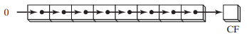
shifts bits one position to the right (logical shift right)
0 gets shifted into most significant bit, least significant gets shifted into the carry flag
SHL: logical shift left
logical shift left fills the lowest order bit with a 0, highest order bit into the carry flag
Syntax: dest, count
dest: source of value to be shifted, and where the result will be stored → memory location, register,
count: number of shifts to perform → must be an 8-bit immediate value or value in CL register (8-bits)
Ex. single logical left shift on 11001111
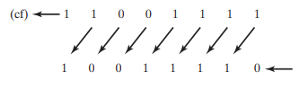
ex 2. shift left twice
mov al, 10001100b
shl al, 2 ; shifts left twice, CF = 0, AL = 00110000b
Can be used for bitwise multiplication
mov dl, 5 [00000101] = 5
shl dl, 1 [00001010] = 10
shift left 1 -→ multiplies value by 2^1
mov dl, 10 [00001010] = 10
shl dl, 2 [00101000] = 40
shift left 2 → multiply value by 2²
SHR Instruction: Logical Shift Right
Bitwise division
Arithmetic Shift
SAL and SAR
SAR(shift arithmetic right)
ex.
mov al, 0F0h [11110000] = -16
sar al, 1 [11111000] = -8
*can be used for signed division
SAL (shift arithmetic left)
copy of lowest order bit
mov al, 11111000b AL = -8
sal al, 1
11/21
INT Instruction
will issue a software interrupt
parameters are often sent through registers and particularly the AH register
Software interrupts will run operating system function
ex
getting user input from keyboard
writing to screen
interacting with hardware drivers
When an interrupt is issued, application program execution pauses, and interrupt code is executed
16 bit mode/real address mode
1MB of linear memory
lower 640k shared between the operating system and the application program
could potentially overwrite data used by OS, because memory isn’t protected
only one application can run at a time
ROM BIOS
read only memory
contains low-level input/output functionality - can be used by applications
Each 16-bit address is mapped to a coordinate on the screen