Magnetic Effects of Electric Current
Magnetism
Known to Greeks over 2000 years ago that 'lodestones' attract iron. Lodestone (now called magnetite ore) is sourced from Magnesia, Turkey.
Chinese utilized magnetic needles for navigation by 400 B.C.
In 1820, Hans Christian Oersted discovered the relationship between electricity and magnetism when he noted that a compass needle deflected in the presence of an electric current.
Sources of magnetism: electric currents and permanent magnets.
Permanent Magnets
Defined as any solid attracting iron, cobalt, or nickel.
Bar magnet is one common shape.
Maximum attraction at magnetic poles, minimum at neutral region.
Properties of a bar magnet:
Attractive nature: Attracts iron filings with maximum pull at poles.
Directive property: Aligns itself to the north-south direction when freely suspended.
Poles exist in pairs: No isolated magnetic poles (if a magnet is broken, each piece becomes a dipole).
Like poles repel, unlike poles attract: South-South or North-North repel; South-North attract.
Inductive nature: Soft iron or nickel nearby can become magnetized (magnetic induction).
Natural vs Artificial Magnets
Natural magnets: Found minerals with magnetic properties, e.g., lodestone.
Artificial magnets: Man-made magnets produced by passing current through materials.
Magnetic Field
Defined as the space around a magnet where it exerts a magnetic force.
Magnetic field lines show the direction and strength of the magnetic field around a magnet.
Properties of Magnetic Field Lines
Arise from the north pole and enter the south pole.
They never intersect, avoiding two-direction conflict for a compass needle.
Strength is indicated by line closeness: crowded lines mean strong magnetic field.
They are continuous curves directed south to north.
Building Concept 2
Use a magnetic bar with an iron rod: Attraction shows magnetism but repulsion indicates confirmed magnetism.
Active Physics Experiments
Iron filings alignment experiment to visualize magnetic field lines.
Compass needle movement shows field lines and direction: Current in a wire produces circular field lines.
How to Make a Permanent Magnet
Use of a Magnetizer: One can create a permanent magnet using a magnetizer device where a piece of metal is exposed to a strong magnetic field. This method helps align the magnetic domains within the material, ensuring a strong magnetization.
Stroke Method: A common method is to stroke a metal object (like a steel bar or nail) with a strong magnet in one direction (and not back-and-forth), which aligns the magnetic domains within the object. A consistent stroke helps create a strong permanent magnet.
Electromagnet Method: Wrap copper wire around an iron object and connect it to a power source to magnetize it while current flows. The strength of magnetization can be enhanced by increasing the number of wire turns or the amount of current applied. If kept magnetized after removing current, it can turn into a permanent magnet when allowed to cool or after being placed in a magnetic field.
Magnetic Field in Conductor and Solenoid
Straight Current-Carrying Wire: Produces circular magnetic field lines in concentric circles around the wire. The right-hand thumb rule is applied here to determine the direction of the magnetic field: if you hold the wire with your right hand such that your thumb points in the direction of the current, the fingers curl in the direction of the magnetic field lines.
Magnetic field produced by straight carrying- current conductor is directly proportional to the amount of current flowing through the conductor and inversely proportional to the distance from the wire.
Magnetic Field Due to a Current-Carrying Circular Loop: A circular loop of wire carrying an electric current produces a magnetic field similar to that of a bar magnet, having distinct north and south poles. The magnetic field lines emanate from the north pole, looping around and re-entering at the south pole.
The strength of the magnetic field at the center of the loop can be increased by increasing the current or by increasing the number of loops in the wire. The field lines are denser in the center, indicating a stronger magnetic field as compared to further away from the loop.
Solenoid: A solenoid is a long coil of wire that is tightly wound in the shape of a cylinder. When electric current passes through the wire, it generates a magnetic field.
Magnetic Field Lines Produced by a Solenoid:
Inside the solenoid, the magnetic field lines are parallel, indicating a strong and uniform magnetic field.
The magnetic field direction aligns from the north pole to the south pole of the solenoid.
At the ends of the solenoid, the magnetic field is weaker and tends to spread out, resulting in a less concentrated magnetic field than inside the solenoid.
The strength of the magnetic field within a solenoid can be increased by increasing the amount of current or by increasing the number of loops of wire in the solenoid. This configuration is crucial in many applications of electromagnets.
Electromagnet: A soft iron piece can be magnetized using a solenoid. this magnet is called electromagnet. when the current flows the iron acts like magnet and when the current is ceases to glow the core loses it’s magnetisation.
Uses - switches, electric bells, metal lifting cranes.
Mumetal- nickle,iron and copper is used in making electromagnet.
The strength of the magnetic field produced can be varied by controlling the current flowing through the wire. The type of core material also significantly influence the strength of the electromagnet. Increasing the number of coil turns enhances the magnetic field.
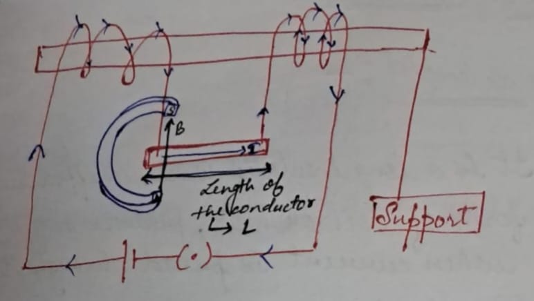
Force on Current-Carrying Conductors
when a conductor is placed in exrenal magnetic field, then a force is exerted by magnetic field on this conductor.
the direction of this force is defined by fleming’s left hand rule and it depends always on the direction of magnetic field and current.
this force is directly proportional to a magnetic field, currrent in conductors and leght of conductors.
Fleming's Left-Hand Rule: It states that stectch fingers of your left hand, in a manner that thumb, index and center finger are perpendicular to each other. Thumb = force/motion, forefinger = field, central = current.
Applications: Used in electric devices like motors, generators, etc.
Force on a charged particle in magnetic field
When a charged particle moving with velocity v, is placed inclined in a magnetic field then it's path becomes circluar and centripital force is provided by magnetic force.
Electric Current Types
AC (Alternating Current): The electric current, whose magnitude varies time and direction reverses periodically, provided its amplitude is constant.
the frequency of AC is 50Hz(50 cycles per second) the direction of AC changes 100 times.
DC (Direct Current): the eletric current, whose magnitude and direction do not vary with time. Used in batteries.
Advantages of AC over DC
AC, Easily transformed to higher or lower voltages.
AC, Better for long-distance transmission due to reduced losses.
AC, Generally cheaper to produce current.
AC, simple, robust and require less care.
Disadvantages of AC
Higher danger levels compared to DC.
AC, Fluctuates significantly in voltage.
AC, Not suitable for processes requiring steady current, like electroplating.
An AC flows mainly on the surface of confuctor(called sink effect). thus, instead of a single thick wire, w hace to use several thin wire twisted to form a main wire, which increases its cost of manufacturing.
Domestic Electric Circuits
Overview: Electricity is supplied to houses via overhead poles with aluminum wires or underground cables. There are two main wires: the live wire (positive), typically with red insulation, and the neutral wire (negative) with black insulation, both carrying a potential difference of 220 V.
These wires enter the electricity meter through a main fuse connected in series with the live wire, leading to line wires that distribute electricity to various circuits. There are generally two circuits: one with a 15 A current rating for high-power appliances (like geysers and refrigerators) and another with a 5 A rating for standard devices (like lights and fans).
An earth wire, which is green, connects to a metal plate in the ground for safety. This wire diverts any leakage current to the earth, preventing electric shocks from devices with metallic bodies. Each device in the circuit is connected across the live and neutral wires and has its own switch, allowing them to be operated independently, and all devices are arranged in parallel, ensuring equal potential difference across them.
Key Components:
Fuses: Devices used to prevent overloads in electrical circuits.
It is combination of 75% lead and 25% tin.
Have high resistance and low melting point.
Always connected in the series of live wires.
They are rated according to the expected current load of appliances. the rating of the fuse is directly proportional to the radius of the wireand doesn’t depend on the lenght of wire.
Wiring: Different wiring methods can be employed for safety and efficiency in domestic circuits.
Overloading Conditions:
Overloading is a condition in which excessively high current flows through a circuit.
Short Circuits: Occur when there is a direct connection between live and neutral wires, leading to excessive current flow.
Voltage Surges: Suppliers may experience sudden increases in voltage, potentially damaging appliances.
Multiple Device Usage: Connecting too many devices to a single outlet can cause overload.
Safety Measures: Implementing proper safety protocols is essential to avoid overloads and maintain a secure electric supply throughout the home
Use fuses to prevent overloads; specifications based on appliance ratings (5A for lighter, 15A for heavier).