Electricity
The flow of charged particles–usually electrons. Due to the sea of delocalised electrons, electrons can move, or flow, freely through metals, which is why metal makes a good conductor of electricity.
Potential Difference: Difference between the positive and negative terminals, the amount of force its going with. Measured in Voltage (V).
Amps: The current, meaning how much electricity is flowing through a circuit represented with an A or I.
Resistance: Like an opposition to the voltage slowing down the electricity, the less resistance the more flow.
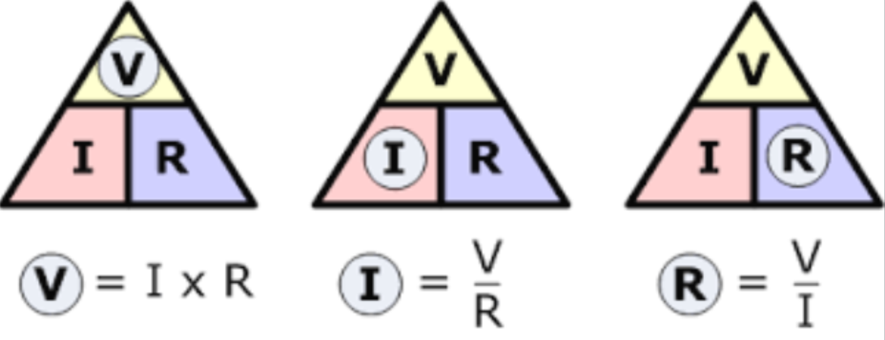
Ohm’s Law: George Ohm discovered the relationship between current, voltage and resistance. He found out that the voltage across a component is directly proportional to the current through it. If the current through a resistor increase, the voltage increases too.
V=IR, and you can change this as seen by the triangle,
You can use diagrams to represent a circuit.
1. Essential Components of an Electric Circuit
Power Source
: Provides voltage (e.g., batteries, power supplies).
Conductors
: Wires that allow charge to flow (usually copper).
Load
: Component that consumes electrical energy (e.g., light bulbs, resistors).
Switch
: Controls the flow of current, allowing the circuit to open or close.
2. Charge Flow in an Electric Circuit
Current flow
: Electric charge flows in a closed circuit from the negative terminal of the power source to the positive terminal.
Conventional current
: Defined as flow of positive charges, moving from positive to negative. Actual electron flow is opposite.
3. Diagrams of Basic Circuit Components
Battery
: (Draw symbol: a pair of long and short parallel lines).
Wire
: (Straight line).
Resistor
: (Zigzag line).
Switch
: (Break in the line with a pivot).
Light Bulb
: (Circle with a cross inside).
4. Series vs. Parallel Circuits
Series Circuit:
Components are connected end-to-end.
Total resistance increases with additional loads.
Current is the same through all components.
Parallel Circuit:
Components are connected across the same voltage source.
More pathways for current to flow.
Voltage across each component is the same.
5. Circuit Diagrams for Series and Parallel Circuits
Series Circuit Diagram
:
Connect components one after another.
Draw a loop.
Parallel Circuit Diagram
:
Connect components in separate branches.
Each branch can be individually addressed.
6. Constructing Circuits
Use wires to connect components according to your diagrams.
Ensure connections are secure to prevent short circuits.
7. Definitions in Electric Circuits
Current (I)
: The flow of electric charge, measured in
Amperes (A)
.
Voltage (V)
: The potential difference, measured in
Volts (V)
.
Resistance (R)
: The opposition to current flow, measured in
Ohms (Ω)
.
8. Measuring Current, Voltage, and Resistance
Ampere meter (Ammeter)
: Measures current (place in series).
Voltmeter
: Measures voltage (place in parallel).
Ohmmeter
: Measures resistance (not in active circuit!).
9. Correct Placement of Meters
Ammeter
: Should be connected in series with the load to measure the total current.
Voltmeter
: Should be connected in parallel to the component to measure the voltage across it.
10. Ohm’s Law
Formula:
Where:
= voltage (volts)
= current (amperes)
= resistance (ohms)
Can be rearranged to calculate any one of the three variables as needed.
11. Applying Ohm’s Law
Example Calculations:
If and ,
Calculate Voltage:
If and ,
Calculate Resistance:
12. Identifying and Mitigating Hazards in Experiments
Electrical shock
: Ensure circuits are not live before connecting/disconnecting components.
Overheating
: Monitor components for excessive heat; avoid overloading circuits.
Short circuits
: Check connections to prevent unintended current paths that could cause sparks.
13. Resistance and Its Relationships
Length
: Resistance increases with length of the wire due to more collisions between charges and atoms.
Thickness
: Thicker wires have lower resistance; more space for charge flow.
Temperature
: Higher temperatures generally increase resistance due to more atomic vibrations. (For metals).