2.1.1 Microscopy
2.1.1 Cell structure (a-f)
Microscopy - Notes
2.1.1a: the use of microscopy to observe and investigate different types of cell and cell structure in a range of eukaryotic organisms
Describe, in principle, what a microscope does and name 4 different types of microscope. (F)
Label a diagram of a light microscope with the names of the component parts and annotate this diagram with the functions of these parts.
State what “SEM” and “TEM” are abbreviations for. (F)
Outline how an SEM works.
Outline how a TEM works.
Draw a table comparing the use and properties of light, SEM, and TEM microscopes. (F)
State the features of the images produced from light, SEM, and TEM microscopes.
Identify the type of microscope used when presented with a photomicrograph.
Create an annotated timeline showing the development of the microscope up to the present day. (S+C)
Suggest how the development of the microscope influenced scientific thinking and what the wider consequences of this might have been. (S+C)
2.1.1b: the preparation and examination of microscope slides for use in light microscopy
Explain how to use a light microscope to view a specimen at low and high powers.
Describe how to produce a temporary wet mount of living tissue.
Describe and explain the characteristics of a good slide preparation.
Explain why slide preparations need to be thin. (F)
Explain how to use a stage micrometer to work out the distance represented by the small divisions in an eyepiece graticule under 3 different objective lenses. (F)
Explain how to use a stage micrometer and eye-piece graticule to add a scale bar to a drawing.
Explain how to use a stage micrometer and eye-piece graticule to calculate the size of a specimen.
Describe how to choose an appropriate number of significant figures, or decimal places to present data.
Explain how an adjustment to the “plane of focus” can alter what is viewed within a cell. (F)
Explain how a tissue slice might be misleading due to the very thin nature of the slice.
2.1.1c: the use of staining in light microscopy.
Explain why staining is useful for light microscopy. (F)
Describe the properties a stain needs to have to be useful for light microscopy. (F)
Describe how to prepare a stained specimen for viewing under a light microscope.
Name two common stains and the molecules they bind to. (S+C)
2.1.1d: the representation of cell structure as seen under the light microscope using drawings and annotated diagrams of whole cells or cells in sections of tissue.
State the rules for biological drawings. (F)
Produce a labelled and annotated low power tissue plan using a light microscope.
Produce a labelled and annotated high power drawing of a named number of cells using a light microscope.
2.1.1e: the use and manipulation of the magnification formula.
State the magnification formula and represent the magnification formula in a triangle diagram. (F)
Explain the usefulness of a “triangle diagram” for a simple equation.
Explain how to calculate the magnification of an image using the magnification formula. (F)
Explain how to calculate the actual size of an object using the magnification formula. (F)
State the symbols used for millimetres, micrometres and nanometres. (F)
Explain how to convert measurements from one unit into another.
Explain how to represent numbers in standard form.
Describe ways to estimate results in order to “sense check” that calculated values are appropriate.
2.1.1f: the difference between magnification and resolution.
Define the terms “resolution” and “magnification”. (F)
State the difference between magnification and resolution.
State the resolution and useful maximum magnification of light microscopes, SEMs and TEMs.
Microscopes
Microscopes enlarge the image of an object to allow us to see objects, or the details of objects, that are not observable with the naked eye.
The microscopes used in schools are called compound light microscopes.
Three types of microscope that are very important in scientific research are:
transmission electron microscopes (TEM)
scanning electron microscopes (SEM)
Laser scanning confocal microscopes
The compound light microscope
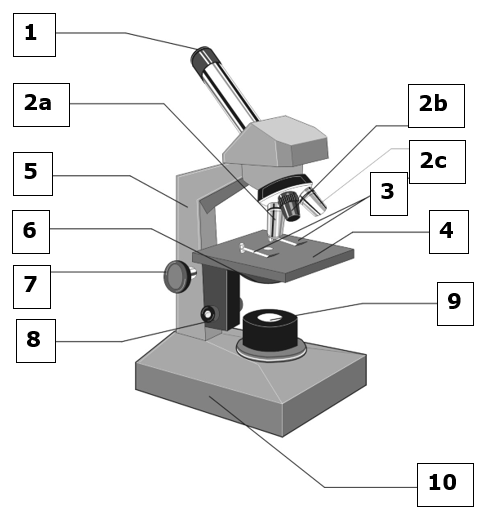
1. Eyepiece (often x10 magnification)
2a. High-power objective lens (often x40 magnification)
2b. Low-power objective lens (often x4 magnification)
2c. Medium-power objective lens (often x10 magnification)
3. Stage clips
4. Stage
5. Arm
6. Condenser (fixed in place in our microscopes)
7. Coarse focus
8. Fine focus
9. Light source
10. Base
Always carry a microscope by holding the base in one hand and the arm in the other.
When you finish using a microscope ensure that the low-power objective lens is in place, that you have removed your slide, and that you have replaced the eye-piece with the eye-piece graticule in it with the normal eye-piece.
How to observe a slide using a compound light microscope
Check that the low-power objective lens (the smallest one) is in the viewing position.
Using the coarse focus move the stage up as close to the objective lens as it can go.
Place the slide on the stage and hold the slide in place using the stage clips if they are present. Make sure that the specimen is on the upper surface of the slide otherwise you won’t be able to see it when using the high-power objective lens.
Turn the light source on (check that it is switched on at the plug, on at the base, and the dimmer switch is not at the lowest it can be.
Check that the specimen on the slide is in the centre of the beam of light shining on the slide.
Look down the microscope (look through the eyepiece) and adjust the light intensity for comfort.
Whilst looking down the microscope slowly turn the coarse focus to lower the stage until the specimen comes into focus. It may help to move the slide from side to side a very small amount to help you find what you’re looking for. Sometimes it’s possible to focus on dust on the upper or lower surface of the slide and not the specimen itself – just make sure you have an idea of what you are looking for before you start.
To increase the magnification ensure that the specimen is directly in the centre of the field of view and move the medium-power objective lens into place by rotating the nose-piece.
Your image may now not quite be in the centre of the field of view and may be slightly out of focus. Refocus using the coarse or fine focus. You won’t know which way to turn it so turn it slowly and look to see if your image is getting better or worse. If it’s getting worse or there’s no change then you’re turning it the wrong way. You may also need to adjust the light intensity.
To increase the magnification further repeat steps 8 and 9 but switch in the high-power objective lens and only use the fine focus when refocusing your image.
If, at any point, you can’t re-find your specimen, go back to the low-power objective lens and start again.
Units of distance, area and volume
![]()
![]()
![]()
![]()
Length | Equivalent in: | |||
cm | mm | µm | nm | |
1cm | 1 |
|
|
|
1mm |
| 1 |
|
|
1µm |
|
| 1 |
|
1nm |
|
| 1 | |
Length | Equivalent in (written in standard form): | |||
cm | mm | µm | nm | |
1cm | 1x100 |
|
|
|
1mm |
| 1x100 |
|
|
1µm |
|
| 1x100 |
|
1nm |
|
|
| 1x100 |
To convert units of area you need to square the distance conversion factor and to convert units of volume you need to cube the distance conversion factor.
e.g. 1cm=10mm, 1cm2=10x10mm2=100mm2, 1cm3=10x10x10mm3=1000mm3
![]()
![]()
![]()
1mm=1000µm, 1mm2=1,000,000 µm2, 1mm3 = 1,000,000,000µm3
The eyepiece graticule and the stage micrometer
The eyepiece graticule is your measurer – whenever you measure objects using a microscope you measure in eye piece units (epu) and then convert this to an actual length.
It's in the eyepiece so remains in your view no matter what's on the stage. However, it remains constant even if you change objective lenses. This means that the divisions of the eyepiece graticule represent different distances depending on the magnification you are viewing objects at.
We need to work out what distance each epu represents for each objective lens. This is called calibrating. It means that, once we've done this, we can measure objects in epus and then convert this to actual distances by multiplying by the length of each epu.
The stage micrometer is a slide you put on the stage. It is a tiny ruler. It allows you to measure the length of an epu (and so to calibrate your microscope).
Stage micrometers vary - you need to know what distance they represent and how they divide up this distance.
General Equation for calibrating
How to calibrate each objective lens
Switch the normal eyepiece for one with an eyepiece graticule in it
Focus the microscope on the stage micrometer
Line up the eye-piece graticule with the stage micrometer
Find two division lines of the stage micrometer that line up nicely with two division lines on the eye-piece graticule. The further apart the division lines are on the stage micrometer the better (so long as they are within your field of view)
Work out the distance between these two division lines on the stage micrometer
Count how many epus there are between the two division lines on the stage micrometer
Put your answers to step 5 and step 6 into the equation for calibrating to work out the length of each epu and write this in the table below
Repeat for the other two objective lenses
Table for recording calibration values [take a photo of this so you have it for future microscopy work]
Objective lens being used | Magnification you are viewing at | Distance one numbered eye-piece unit represents |
X4 | X40 | |
X10 | X100 | |
x40 | X400 |
For more help calibrating watch: https://www.youtube.com/watch?v=HXTqaUTGrKg

It explains things very clearly but does mention some things that aren’t relevant to us or are slightly different for us:
You don’t need to know about “Kohler illumination” – you just turn the light on and adjust the brightness to get the best image and to suit your eyes.
Our microscopes have a single eye-piece whereas the one in this clip has two.
They use the term “ocular micrometer” whereas we use “eye-piece graticule” for the same thing.
They use the abbreviation “O.U.” whereas we use “epu” for the same thing.
We have two different types of eye-piece graticule (ocular micrometer) one that looks exactly like the one in the clip (going from 0-10) and one that goes all the way across the area you’re looking at (going from 0-16). There is no difference in how you use each type.
We have two different types of stage micrometer. One is 1cm in length, divided in numbered mm and then each mm is divided into 10 divisions (so the maths would be a bit different to the example in the clip). The other is 1mm in length, and is divided into 10 major divisions, and 100 divisions overall, none of which are numbered (this is the same as in the clip but nothing has numbers attached to it on ours).
A micron = a micrometre.
You will record your calibration results on this sheet and use whenever you are using the microscopes (even if you are using a different one).
Preparing slides
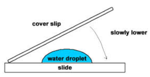
A ‘wet mount’ is when a drop of water is put on a slide, the specimen is added and a coverslip is put on top. A coverslip is a very thin square piece of glass that protects the objective lens from the specimen and helps to keep the specimen flat and in place.
To minimise the number of air bubbles in the specimen the coverslip is lowered onto the specimen and drop of water at an angle.
Specimens must be thin so that they are easily observable. Light needs to pass through the specimen and there shouldn’t be too many layers of cells on top of each other so that the specimen can be observed clearly.
If a specimen is too thick it can be sliced before viewing. Sometimes this just involves cutting fresh tissue by hand with a sharp scalpel. However often the specimen needs to go through a complex preparation process before it can be viewed under the microscope.
These steps are often used:
Fixing - Specimens can be “fixed” to preserve specimens in as near-natural state as possible.
Sectioning – Specimens that are too thick need to be sliced. They are dehydrated with alcohols, placed in a mould with wax or resin to form a hard block. This block is then sliced very thinly with a knife (or cutting machine) called a microtome.
Staining – specimens are often treated with multiple stains to show different structures.
Mounting – specimens are secured to a microscope slide and a cover slip placed on top. This can then be sealed to create a permanent slide.
A good slide preparation will:
Be flat so that a lot of the specimen is observable in the same focal place
Be thin, with cells spread out where relevant so that there isn’t much overlap of cells
Allow light through (being thin helps with this)
Have no artifacts (these are observable features that are to do with the preparation process and not present in the specimen normally) e.g. air bubbles.
Have good contrast to show key features of the specimen well (staining is often used to make this better).
Use clean slides and coverslips so the image of the specimen is not obscured.
Have an appropriate volume of liquid in a wet mount – enough so that everything under the coverslip is in water but not so much that the coverslip is floating or that the liquid spills out from under the coverslip.
Examining slides
When you observe a specimen under the microscope you are only ever focussed on a narrow layer of the specimen. All of the rest is out of focus, of even not there if the specimen has been sliced. Because of this we are always observing a 2-D section of a 3-D object and so careful interpretation is needed.
Microscopes optically section a specimen because only a thin section is in focus at any one time. This section is called the “focal plane”, or “plane of focus”. Focusing through a 3-D cell will bring different objects into focus in different focal planes.
Similar to the “focal plane” idea above, a tissue section is only one section of the tissue as a whole. Cells may not appear to have a nucleus just because the nucleus was outside the section that is now on the slide. Likewise, separate objects on the slide may not have been separate objects in the 3-D specimen – the connecting part of the cell may have been outside the section taken.
Also, objects may look different shapes depending on the angle that they have been sliced.
What shapes could be observed in a section if the original object was a cylinder?
Staining in light microscopy
Staining allows transparent objects to become visible by creating a contrast (in colour, or intensity of colour) between the object and its surroundings.
Once objects can be seen they can then be identified (e.g. particular cell types or structures within tissues or cells).
Stains selectively stain certain molecules and not others so the staining may allow the identification of where particular molecules are present or absent. Different stains bind to different molecules and can be different colours so multiple stains could be used on one specimen. Some stains are polychromatic meaning that they become a different colour depending on which molecules they bind to.
Stains need to:
Allow differential staining – so that there is contrast – i.e. some objects stain and others do not.
Create a very intense colour as there will only be a very small amount of biological material to stain.
Some common stains are:
Toluidine blue – Phloem: red, Xylem: green-blue, DNA: blue.
Methylene blue – DNA blue: binds to negatively charged molecules like DNA.
Eosin – cytoplasm: pink (often used with Haematoxylin)
Haematoxylin – nucleus: blue-violet or brown
Iodine in potassium iodide – starch: blue-black
The table below shows which stains could be used for particular preparations that are named in the specification
Preparation | Stains that might be used |
Root tips for mitosis | Methylene blue (Acetic Orcein) |
Xylem and Phloem in roots, stems, leaves | Toluidine blue |
Gills, Lungs, insect tracheal system, blood cells, mammalian liver, mammalian kidney, pancreas, skeletal muscle | Eosin and Haematoxylin is common (to see pink cells with blue nuclei) Methylene blue could be used to see nuclei. |
Biological drawing
By drawing you observe more carefully. Take time to look and try to draw what you see rather than make up a stylised diagram of the specimen.
There are two types of biological drawing from microscope slides:
A drawing of cells – normally a collection of a small number of cells
A tissue plan – the outline of the regions of different tissue types in a specimen without any cells being drawn
There are conventions to biological drawing that you must adhere to. They are:
Drawings should have an informative title (include what mag. the specimen was viewed under)
Drawing + label lines done with a really sharp pencil (not a pen)
No shading at all – just line drawings
Drawing should take up at least half the page/space
Lines need to be clear and continuous – not ragged or broken
Rule the label lines in pencil (no arrowheads).
Make sure the label lines touch the part you are labelling
Don’t let the label lines cross each other
Ensure the proportions are correct, i.e. different areas are the right size relative to each other, and that your drawing is a true likeness of the slide or biological specimen that you are drawing
Label all the different areas of specimen that you have shown, writing the words in pencil or pen
Annotate labels by writing some information about observable features that are not represented on the drawing (e.g. colour)
Add a scale bar to your drawing at the bottom and not overlapping with the drawing itself.
There are two ways to add a scale bar to a drawing
The simple way is to work out the dimensions of the object you are drawing (more on that later) and then just draw a scale bar that long and write the distance it represents in the middle, just above the line.
If you want your scale bar to be a particular length (e.g. 100µm) then it’s a bit more complicated.
Find the actual, real-life, distance between two points on your drawing by looking down the microscope, measuring in eyepiece units and then multiplying that by how many µm each eyepiece unit is worth.
Use a ruler to measure the distance between the same two points on your drawing.
Divide the distance on your drawing by the real-life distance to get the magnification of your drawing.
Multiply this magnification by the length you want the scale bar to represent. This tells you how long to draw your scale bar line on your drawing.
Measuring and calculating sizes and magnification
To measure an object being viewed under the microscope first measure its length in eyepiece units and then multiply this by the number of µm each eyepiece unit represents.
Sometimes you will be asked to work out the actual size of an object when you are given an image of it and told the magnification of the image. Alternatively, you could be asked to calculate the magnification of an image when you are told the actual size of an object in the image (or from a scale bar in an image).
For both of these you need the equation:
Sometime people find it easy to remember using this triangle:
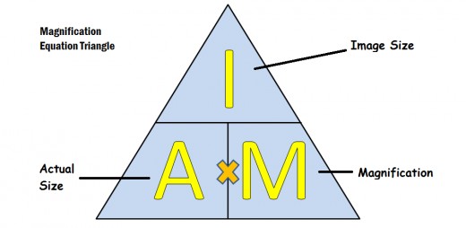
You need to be able to use the equation to calculate any of the 3 values if you are given the other two. Sometimes you’re not given the ‘Image size’ directly but have to measure it from an image provided.
Whenever calculating magnification make sure that the ‘image size’ and the ‘actual size’ values you are using are in the same units.
To help avoid making mistakes it’s best to always measure in mm rather than cm and to help you remember this get yourself a rule with the numbers written in mm rather than cm.
When you give an answer consider the resolution you are quoting your answer to. Your answer should be to the same number of significant figures as the number with the least significant figures used in the calculation.
Magnification and resolution
Magnification is the number of times larger an image is compared to the object, or the degree of enlargement of an image.
Magnification is the degree of enlargement of an image but doesn’t tell us anything about how much detail can be seen in the image. It is possible to enlarge (i.e. increase magnification) without increasing the detail. Magnification is stated as number without units – just “how many times bigger”.
Resolution is the ability to see two objects that are close together as separate objects, allowing the details of objects to be seen.
The resolution of an image is the degree of detail that can be seen and is stated as a distance with units. It is the smallest distance between two objects where these two objects can still be identified as separate.
Exam questions about why some things can be seen and not others are to do with resolution not magnification.
Light microscopy has a limit to its resolution due to the physical properties of light. Electron microscopes have a much higher resolution and were invented so we could see even smaller structures inside cells.
Different sources quote different values for the resolution and maximum useful magnification of different types of microscope particularly for electron microscopes. This is because different technology and techniques are invented and influence these values.
The table below shows the values given to us by OCR.
Type of microscope | Resolution (nm) | Maximum useful magnification |
Light (including laser scanning confocal microscopy) | 200 | X1,500-2,000 |
Scanning EM | 3-10 | X100,000 – 500,000 |
Transmission EM | 0.2-0.5 | X 500,000 – 2,000,000 |
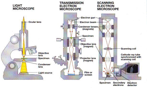
Electron microscopy
There are two main types of electron microscopy: transmission electron microscopy (TEM) and scanning electron microscopy (SEM).
In electron microscopy, a beam of electrons with a wavelength of less that 1nm is used to illuminate the specimen. More detail of cell ultrastructure can be seen because electrons have a much smaller wavelength than light waves. They can produce images with magnifications of between x100,000 and x500,000 for an SEM and between x500,000 and x2,000,000 for a TEM and still have good resolution.
Electron microscopes have changed the way we understand cells but there are some disadvantages to this technique. They are very expensive pieces of equipment and can only be used inside a carefully controlled environment in a dedicated space by people with a high degree of skill and training.
Specimens can be damaged by the electron beam or the complex preparation process so there is a problem with artefacts (visible structures or distortions that are produced due to the preparation process and are not a feature of the specimen). However, as techniques improve a lot of these artefacts can be eliminated.

The inside of an electron microscope is a vacuum to ensure the electron beams travel in straight lines. Because of this, samples must be dead and need to be processed in a specific way. Specimen preparation involves fixation using chemicals or freezing, staining with heavy metals and dehydration with solvents. Samples for a TEM will then be set in resin, sliced to produce ultra-thin sections (about 20-100nm thick) and may be stained again. Samples for an SEM may be fractured to expose the inside and will then need to be coated with heavy metals.
To see an image from an electron microscope the electrons need to be focused onto a fluorescent screen or photographic plate and will produce a “greyscale” image. These images are called electron micrographs. Electron micrographs are sometimes shown in colour, but these colours are added afterwards using specialised computer software. Such images will be labelled as “false-colour” electron micrographs.
The heavy metal salts used for staining in a TEM provide contrast between areas where the heavy metal salts have collected and areas where they have not. Electrons can pass through the ultra-thin sections where heavy metals are absent but cannot pass through areas where they are present.
In a TEM a beam of electrons is transmitted through a specimen being focused using electromagnetic lenses to produce an image. This has a resolution of 0.2-0.5nm.
Staining for SEM involves spraying heavy metals over the surface of the specimen to coat it, and spraying at an angle – called metal shadowing – can enhance contrast.
In an SEM a beam of “primary” electrons is sent across the surface of a specimen using electromagnetic lenses and the “secondary” electrons emitted from the surface are collected. The resolving power is 3-10nm, so the resolution is not as good as with TEM, but stunning three-dimensional images of surfaces are produced, giving us valuable information about the features of the surface of specimens (which could actually be the inside of cells if the freeze fracture technique is used).
Note: these descriptions are summaries, simplifications and generalisations – the true range of techniques available in electron microscopy is much wider as people explore ways to overcome some of the limitations of electron microscopy and enhance the resolution.
Light microscopy
There are many variations of light microscopy where people have invented different techniques to overcome limitations, enhance identification and improve resolution. Some of these variations involve different types of stain, different ways of illuminating the specimen with light, different ways in which the light interacts with the specimen and different ways to process the “light data” from the specimen.
Two types of light microscopy are compound light microscopy (or just light microscopy) and laser scanning confocal microscopy.
In compound light microscopy glass lenses are used to produce a magnified image of light that is transmitted through the specimen.
Although some preparation processes are considerably complex it is often possible to view specimens with practically no preparation or with very simple preparation. Due to this, usually simple preparation process, there is less risk of artefacts than with electron microscopy.
Compound light microscopes are relatively inexpensive and are small and portable requiring only limited training to operate. Because of this compound light microscopy is much more widely available than electron microscopy.
Visible light is not scattered by the atmosphere as electron are, so a vacuum is not required therefore living tissue can be observed (this is also another advantage of the limited preparation required).
Using visible light allows the natural colour of the specimen to be observed as well as allowing the use of a variety of different colour stains within the same specimen to aid identification and contrast.
All light microscopy is hindered by a relatively low resolving power of 200nm and so the maximum magnification whilst retaining clear images is between x1500 and x2000.
Note: As with electron microscopy, people are constantly developing new techniques for light microscopy – some of which are increasing the resolving power of light microscopy.
Comparing light and electron microscopy
Light microscopy | Electron microscopy | |
Radiation used | Light | Electrons |
Radiation source | Light | Electron gun |
Method of focusing | Glass lenses | Electromagnets |
Maximum useful magnification | x1500 – x2000 | TEM: x500,000 – x2,000,000 SEM: x100,000-x500,000 |
Resolution | 200nm | TEM: 0.2-0.5nm SEM: 3-10nm |
Vacuum? | No, scattering of light by air molecules does not affect image production | Yes, scattering of electrons by air molecules interferes with image production |
Specimens | Alive or dead. Can be stained to provide contrast and distinguish different features. Specimens must be relatively thin to let light pass through them. | Always dead since they could not survive in a vacuum. TEM: specimens must be extremely thin to let electrons pass through them. SEM: Specimens don’t need to be thin as electrons bounce off their surface. |
Staining | With a variety of coloured dyes | With heavy metal ions that scatter electrons e.g. Lead or Osmium |
Viewing | Directly with the eye | Electrons hit a fluorescent screen |
Photography | Photomicrographs. Many different possibilities. | Electron micrographs. Only possible in black and white. |
Artefacts? | Possible but relatively easy to eliminate | Can be likely and may be difficult to determine whether something is real or an artefact |
Identifying the type of microscopy from the micrograph
Compound light microscopy Usually a light background due to wide-field illumination. Limited depth of field (appears 2D). A wide variety of colours seen (due to stains or colour of the specimen). Can only view details larger than 200nm. Inside cells the larger organelles are nuclei, mitochondria, chloroplasts and large vacuoles (mitochondria - often only under the highest magnification). Usually observing small organisms, parts of organisms or whole cells. | |
Transmission EM Only greyscale images can be formed – although colour can be added later to form “false-colour” images. Always a 2D image. Very high magnifications used to look at the smaller organelles – making use of the high resolution. Because of this, images of small structures within cells may appear grainy. Objects that are closer together than 200nm can be seen as separate. Usually observing organelles within cells or whole cells. The background is pale as electrons pass through unhindered. | Scanning EM Only greyscale images can be formed – although colour can be added later to form “false-colour” images. Always a 3D image with a larger depth of field. High resolution and freeze fracture allow 3D images of the inside of cells to be observed – often nuclei, Golgi bodies, rough endoplasmic reticulum. Objects that are closer together than 200nm can be seen as separate. The outside surface of specimens can be seen in great detail with a large depth of field. (the inside “surfaces” can be seen through the freeze-fracture process) Usually observing organelles within cells (through the freeze-fracture process) or the surface of small specimens (e.g. insects / diatoms / pollen). Because only reflected electrons are detected the background (if present in the image) is always black. |
Note: In compound light microscopy and transmission electron microscopy the specimens are bathed in the light or electrons a complete image is immediately formed and the background is pale due to the light or electrons passing through unhindered.
In scanning electron microscopy, the image is constructed a pixel at a time by the beam of electrons sampling the specimen one location at a time. It relies on detecting something being emitted from the specimen so where there is no specimen (i.e. the background) the image is black.