CH.9 | PLC COUNTER INSTRUCTIONS
INTRODUCTION
Counter Instructions are used to count parts in manufacturing plants or to count events in industrial control system applications.
9.1 PLC COUNTER INSTRUCTIONS
Like Timer instructions, Counter’s can have a double or single input.
Double_input Counter requires two inputs
One input signal to enable the counter
The other input counts the number of pulse signals
Signals can be either
Trailing-Edge trigger, which is high-to-low
Leading_Edge Trigger, which is low-to-high
Single Input Counter requires one input
One input signal both enables and counts the signals or pulses.
There are two types of counter instructions in PLCs
Count Up
Causes the accumulated register’s value to increment whenever the counter input device changes state.
Count Down
Causes the accumulated register’s value to decrement whenever the counter input device changes state.
9.2 PLC COUNTER INSTRUCTION REGISTERS
Three registers just like Timers
Preset Register (Holds the preset number)
Accumulated Register (Holds the present count)
Status Register (Holds two flag bits)
Count Bit
enabled every time the counter counts up (CU) or counts down (CD)
Done Bit
Enabled whenever the accumulated register is equal to or greater than the Preset Register.
If the counter exceeds the maximum number of 7FFFh (+32767), then it starts over at 8000h (-32767) and its overflow bit turns on.
Overflow Bit (OV) signals an error state in which the number does not fit in the 16 bit register.
If the counter exceeds the minimum number of 8000h (-32767), then it starts over at 7FFFh (+32767) and the underflow bit turns on.
Underflow Bit (UN) signals an error state in which the number to be stored is smaller than the 16-bit register can specify.
There is an addition status bit called the Update Accumulator Bit (UA)
Used with high-speed counter (HSC) instructions.
Not used in Allen-Bradley 500 series.
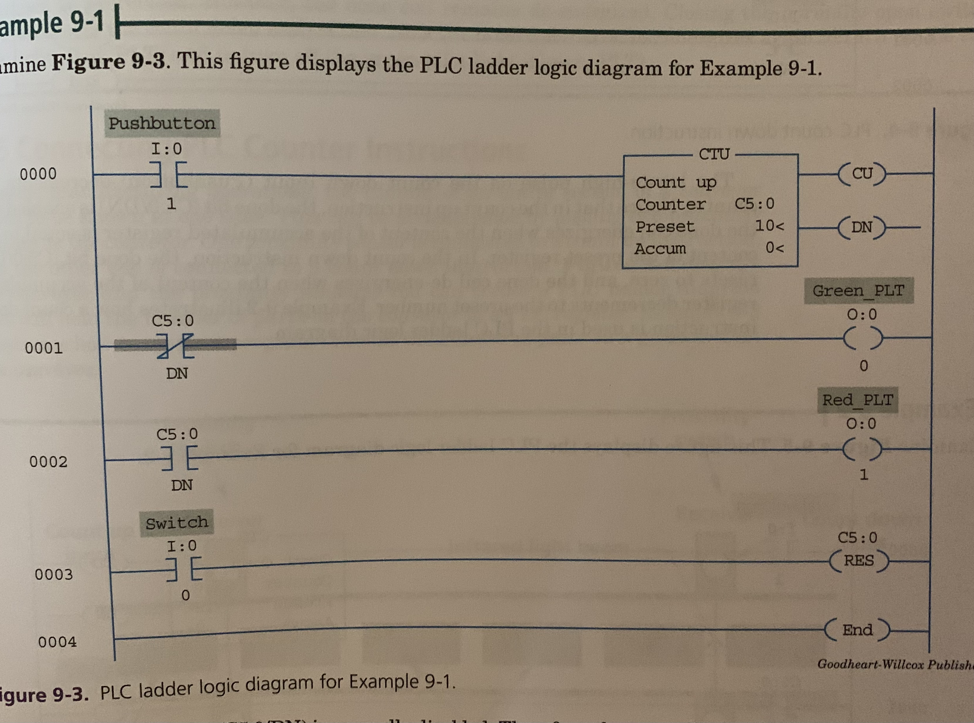
9.3 PLC COUNT UP INSTRUCTIONS
Count Up Instruction
Accumulated register increments whenever the counter input device changes state.
Done bit remains enabled once accumulator is equal to or greater than preset until counter is reset.
Reset (RES) Instruction is used to reset the accumulated register to zero.
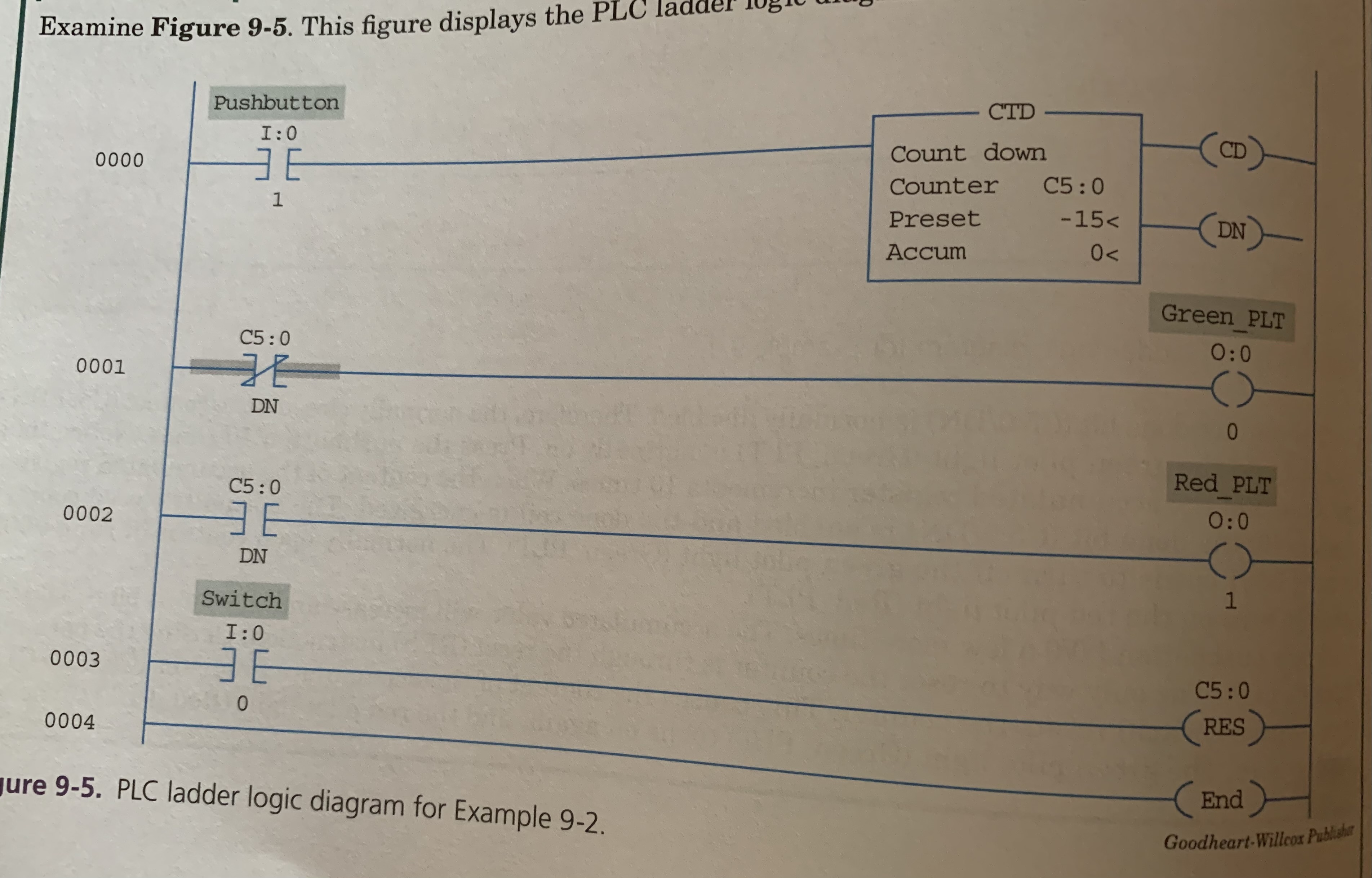
9.4 PLC COUNT DOWN INSTRUCTIONS
Count Down Instruction
The accumulated register decrements whenever the counter input device changes state.
Preset Value is usually a negative number
Therefore the content of the accumulated register decrements from its initial value of ZERO to a negative number.
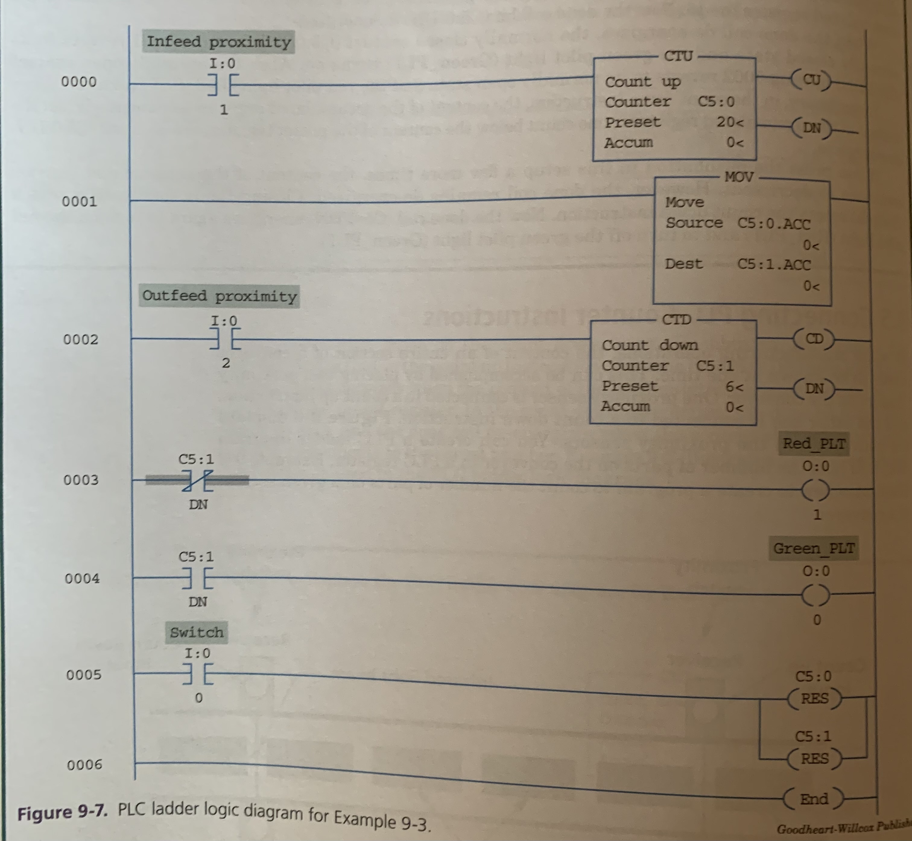
9.5 CONNECTING PLC COUNTER INSTRUCTIONS
Sometimes the content of an entire section of a conveyor needs to be known.
Accomplished by placing TWO proximity sensors.
One sensor is connected to COUNT UP
Another sensor is connected to COUNT DOWN
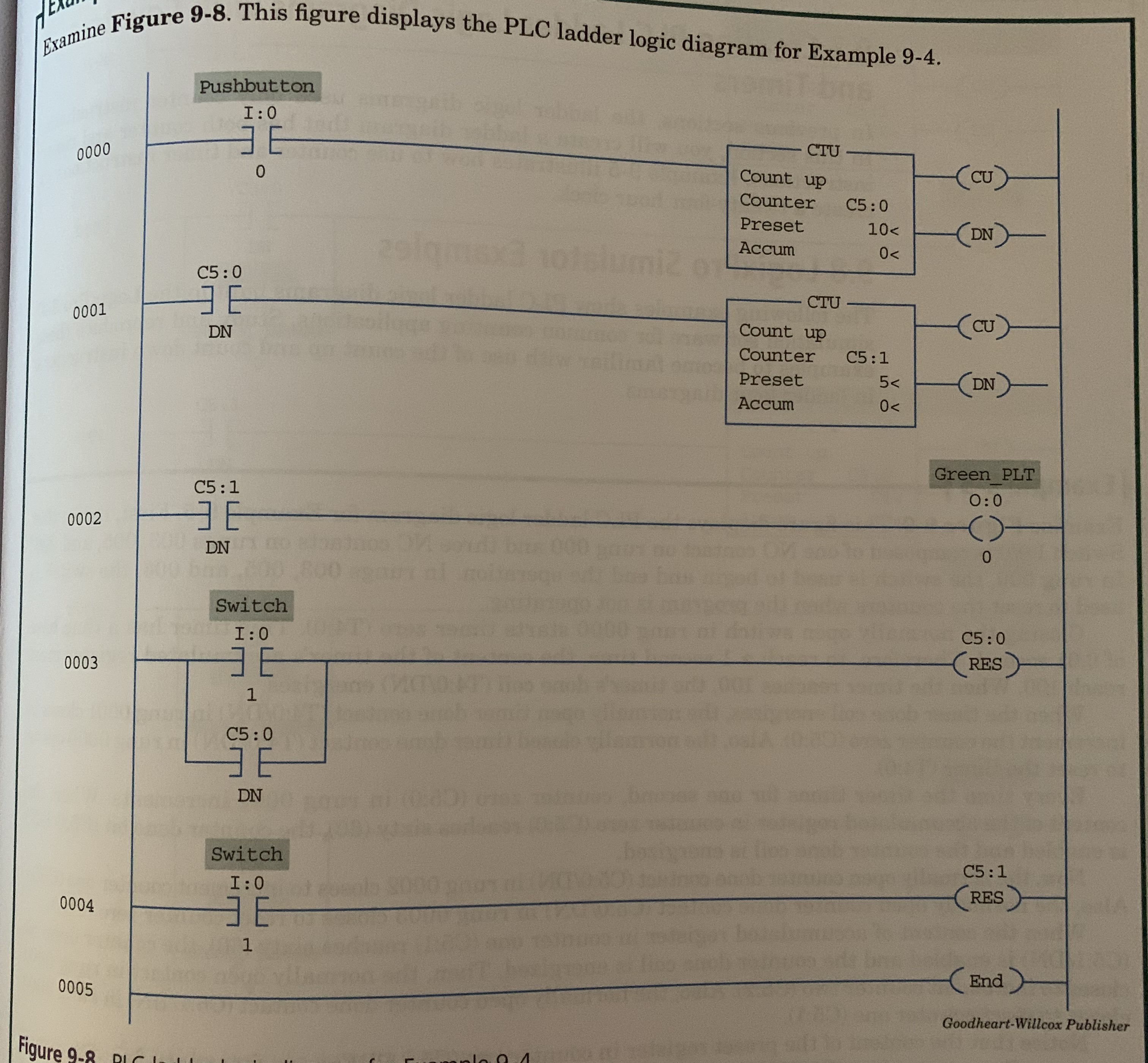
9.6 CASCADING COUNTERS
In some industrial applications, counters are cascaded so that one counter increments or decrements when another is done.
Used mainly in material handling and process control environments.
EX. Six bottles of water are counted and then packed in a container.
One counter counts the bottles then once finished a second counter counts the completed container.