Direct Restorative Materials Adhesive Systems and Mechanical Properties
Evolution and Clinical Importance of Dental Adhesion
Historical Timeline of Dental Bonding:
- 1955 (Dr. Michael Buonocore): Introduced acid etching using phosphoric acid. This technique significantly improved the adhesion of resin restorative materials to enamel by creating surface irregularities.
- 1962 (Dr. Rafael Bowen): Developed Bis-GMA (bisphenol A-glycidyl methacrylate). Combining Bis-GMA resin with silane-coupled inorganic fillers yielded a material that possessed both mechanical durability and aesthetic quality.
- 1970s: Introduction of light-curing technology. This advancement enabled command-setting capabilities, enhanced physical and mechanical properties, and improved color stability.
- 1980s: Introduction of dentin bonding agents and microfilled composites. Microfilled composites improved polishability and aesthetics, while initial dentin adhesives attempted to bond to hydrated tissue.
- 1990s: Development of self-etching primers. These systems eliminated separate acid rinsing steps, streamlining application and reducing technique sensitivity.
Clinical Indications for Dental Adhesion:
- Enables non-retentive aesthetic and functional restorations, including:
- Direct placement of orthodontic brackets.
- Restoration of fractured incisal edge tips.
- Ceramic veneers.
- Resin-bonded bridges (Maryland bridges).
Conservation of Tooth Structure:
- Adhesion eliminates the requirement for aggressive mechanical undercut preparation (e.g., using pear-shaped burs for silver amalgam retention).
- Preserves sound hard tissue, minimizing structural failure risks.
Structural Reinforcement:
- Bonding restores structural integrity to compromised teeth. Loss of a marginal ridge reduces tooth cusp stiffness and increases fracture risk by .
- Non-bonded materials (e.g., amalgam) act as independent wedges, deflecting cusps under occlusal force and predisposing teeth to fracture.
Marginal Seal and Microleakage Prevention:
- Effective bonding creates a tight seal at the restoration interface, mitigating microleakage, reducing postoperative sensitivity, and preventing secondary caries.

- Substrate-Specific Bonding Protocols:
- Enamel: Phosphoric acid etching followed by unfilled resin bonding agent.
- Dentine: Dentine bonding agent system (creating a hybrid layer via etching or conditioning).
- Resin Composite: Direct chemical bonding via unreacted methacrylate groups or mechanical roughening/priming for aged composite.
- Ceramic: Hydrofluoric acid etch followed by a silane coupling agent, or resin cement luting.
- Metal: Mechanical surface roughening (grit blasting with aluminum oxide) paired with a specialized metal primer.
- Glass Ionomer Cement (GIC) / Resin-Modified GIC (RMGIC): Polyacrylic acid conditioning to bond chemically to enamel and dentine without needing separate adhesive resins.
Enamel and Dentine Surface Preparation Principles
Smear Layer Definition and Composition:
- A thick surface deposit created during rotary or manual cavity preparation.
- Composed of mineralized collagen debris, hydroxyapatite (HAP), denatured dentine proteins, bacteria, cellular debris, and saliva.
- Functions as a physical barrier that obstructs direct contact between restorative resins and the underlying intact tooth structure.
Comparison of Surface Preparation Reactions:
- Etching:
- Uses phosphoric acid (strong acid, ).
- Completely removes the smear layer and dissolves superficial mineral.
- Demineralizes the surface, creating microporosities (microscopic holes) for mechanical interlocking and micro-retention.
- Enamel effect: Selectively dissolves enamel crystal prisms to increase surface area and surface free energy.
- Dentine effect: Removes smear plugs and demineralizes peritubular and intertubular dentine to expose the collagen matrix.
- Conditioning:
- Uses polyacrylic acid (weaker acid).
- Modifies and cleans the smear layer without completely removing it or stripping intrinsic tooth minerals.
- Increases smear layer permeability, enabling weak chemical bonding between polyacrylic acid carboxyl groups and calcium in hydroxyapatite.
Technique Sensitivity of Acid Etching:
- Syringe Application: Etchant gel must be placed precisely via a syringe tip.
- Prohibition of Rubbing: Etchant must never be rubbed into the enamel or dentine surface with a microbrush. Rubbing collapses delicate microporosities and flattens the etched prism pattern, reducing bond strength.
- Over-Etching Risk: Prolonged acid exposure dissolves excessive mineral content deeper than adhesive resin can penetrate, creating a structural weakness beneath the interface that leads to post-operative sensitivity and reduced bond durability.

Mechanisms and Failures of Enamel Bonding
Micromechanical Retention Mechanism:
- Enamel bonding depends on acid etching to create surface relief, followed by capillary penetration of low-viscosity resin into microscopic spaces.
- Polymerization locks resin tags within the enamel matrix.
Etching Patterns in Enamel:
- Type I (Prismatic): Selective dissolution of enamel rod/prism cores, resulting in a distinct honeycomb microscopic topography.
- Type II (Interprismatic): Selective dissolution of rod peripheries (interprismatic region), leaving intact rod cores and a cobblestone-like appearance.
- Type III (Mixed): A combination of Type I and Type II etching features, showing irregular surface erosion.


Bond Strength Comparison:
- Prismatic (Type I) etching yields higher bond strengths than interprismatic (Type II) etching.
- Mixed etching (Type III) exhibits inconsistent bonding performance.
- All three etching patterns provide clinically acceptable bond strength.
Surface Energy Modification:
- Acid etching removes contaminants (salivary pellicle, smear layer) and increases the surface tension/surface energy of enamel, facilitating wetting by hydrophobic resin monomers.
White Lines and Marginal Defects:
- "White lines" are visual optical fractures appearing at restoration enamel margins.
- Causes:
- Unsupported Enamel: Micro-cracking of fragile enamel rods unsupported by dentine due to composite polymerization shrinkage stress.
- Composite Cracking: Thin, high-stress margins of composite resin fracturing under heavy occlusal forces.
- Thermal Damage: Excessive frictional heat generated during dry finishing and polishing.

Categories of Enamel Bonding Failures:
- Adhesive Failure: Fracture occurring directly at the interface between enamel and resin. Primary cause is moisture or salivary contamination prior to resin placement.
- Cohesive Failure: Fracture occurring entirely within the substrate material (either within the enamel itself or within the restorative composite/luting cement).
Clinical Optimization Methods:
- Rubber Dam Isolation: Eliminates blood and saliva contamination during bonding. Without isolation, failures are predominantly adhesive; with proper rubber dam isolation, failures are limited to cohesive modes.
- Margin Beveling: Creating a sloped finish line on enamel margins (avoided on direct occlusal contact points):
- Removes weak, unsupported enamel rods.
- Increases total available enamel bonding surface area.
- Exposes rod ends perpendicular to their long axes for optimal etching.
- Improves aesthetic blending between composite resin and natural tooth tissue.

Dentine Bonding Mechanism and Hybrid Layer Formation
Substrate Challenge:
- Unlike enamel (which is mineralized and inorganic), dentine is a complex, vital, hydrated substrate composed of inorganic hydroxyapatite, organic material (predominantly Type I collagen), and water by weight.
The Hybrid Layer (Resin-Infiltrated Layer):
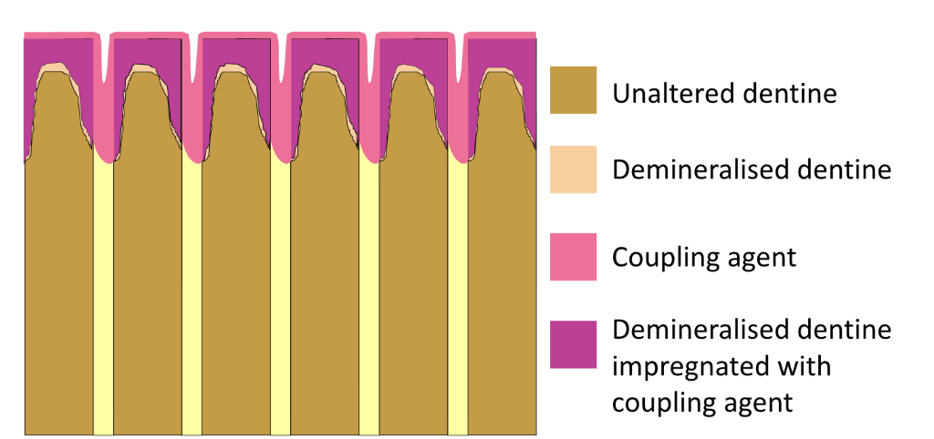
- A thick structural zone created by the infiltration of adhesive monomers into the demineralized collagen network of dentine.
- Components: Demineralized dentine matrix + collagen fibrils + residual hydroxyapatite + polymerized primer/coupling agent.
- Creation of an intact, homogenous hybrid layer is the central objective of dentine adhesion.

- Step-by-Step Dentine Bonding Sequence:
- Acid Etching:
- Phosphoric acid removes the smear layer, opens dentinal tubules, and demineralizes surface dentine to a depth of , exposing the delicate collagen fibril network.
- Consequence of Over-Etching: Etching deeper than demineralizes dentine beyond the penetration depth capability of adhesive monomers. This leaves an unsealed, resin-devoid collagen layer filled with fluid at the base, causing persistent post-operative sensitivity and hydrolytic breakdown.
- Primer Application (Coupling Agent):
- Acts as a mediator between hydrated dentine collagen and hydrophobic restorative resins.
- Bifunctional Monomer Architecture: Consists of molecules possessing two distinct functional ends linked by a spacer:
- Hydrophilic End Group: Contains hydroxyl (), carboxyl (), or phosphate () groups. Bonds chemically to calcium () in hydroxyapatite and forms hydrogen bonds with collagen amino (), amido (), hydroxyl, and carboxyl groups.
- Hydrophobic End Group: Contains polymerizable methacrylate moieties that copolymerize with restorative resin monomers.

 - **Primer Formulation**: Contains bifunctional monomers, photo-initiators, and volatile organic solvents (ethanol, acetone, or water).
 - **Solvent Drying**: Solvents lower resin viscosity to promote penetration into collagen meshwork. Solvents **must** be evaporated using gentle air drying. Excessive air blast collapses the collagen network, preventing monomer entry; inadequate evaporation leaves solvent trapped, impeding complete polymerization and causing microleakage.
- Bonding Agent Application (Adhesive/Sealer):
- Consists of solvent-free or low-solvent resins containing minimal inorganic fillers (e.g., HEMA, Bis-GMA).
- Flows into micro-cavities, seals open tubule orifices, forms resin tags, and copolymerizes with the primer.
- Placement of Composite:
- Viscous, highly filled composite resin or luting agent is placed and light-cured directly over the adhesive layer.

Breakdown Mechanisms, C-Factor, and Bond Longevity
- Factors Causing Dentine Bonding Breakdown:
- Polymerization Shrinkage: The principal cause of bond disruption. Resin contraction creates tensile stress at the adhesive joint before full bond strength is reached (which takes up to ). This mechanism causes ceramic veneer debonding when placed over sclerotic dentine.
- Configuration Factor (C-Factor):
- Defined as the ratio of bonded surface area to unbonded (free) surface area in a cavity preparation:
- Higher C-factors restrict plastic flow of composite during curing, dramatically raising internal contraction stress and disrupting the adhesive interface.
- Examples:
- Flat surface (Class V facial): 1 bonded / 5 free = C-factor
- Box preparation (Class I): 5 bonded / 1 free = C-factor
- Clinical Management: Compensate for high C-factor preparations using incremental layering techniques ( increments).
- Handling Errors: Incorporation of air voids, inadequate solvent evaporation, or improper curing light intensity.
- Thermal Stress: Repeated cyclic temperature fluctuations induce differential expansion and contraction between tooth tissue and composite due to mismatched coefficients of thermal expansion.
- Mechanical Load: Repetitive occlusal stress concentrations causing interfacial fatigue.
- Chemical Degradation: Hydrolysis of exposed, resin-devoid collagen fibrils by endogenous matrix metalloproteinases (MMPs) and cysteine cathepsins present in dentine.
- Improving Bond Longevity with Chlorhexidine (CHX):
- Mechanism: Application of chlorhexidine solution acts as a synthetic inhibitor of MMPs (specifically MMP-2, MMP-8, and MMP-9).
- Clinical Benefit: Prevents enzymatic cleavage of collagen fibers within the hybrid layer over time, preserving bond durability.
- Clinical Application Protocol:
- Apply phosphoric acid etchant, rinse completely, and blot dry.
- Apply chlorhexidine aqueous solution to etched dentine.
- Allow to dwell for .
- Gently air-dry to remove excess solvent moisture without rinsing the CHX away prior to primer/adhesive application.
Generations of Dental Adhesive Systems and Monomer Chemistry
| Generation | System Type | Bottle Count | Application Characteristics | Commercial Examples |
|---|---|---|---|---|
| 4th Gen | Etch & Rinse (Total Etch) | 3 bottles | Separate Etch + Separate Prime + Separate Bond | OptiBond FL |
| 5th Gen | Etch & Rinse (Total Etch) | 2 bottles | Separate Etch + Combined Prime-Bond bottle. Yields lower bond strengths than 4th Gen. | Optibond Solo Plus (utilized in JCU clinics) |
| 6th Gen | Self-Etch (No Rinse) | 2 bottles | Self-etching primer bottle + Separate Bond bottle (no acid rinse step) | Clearfil SE Bond 2 |
| 7th Gen | Self-Etch (No Rinse) | 1 bottle | Combined All-in-One Etch-Prime-Seal (no rinsing, no mixing) | Scotchbond Universal, iBond Universal |
| 8th Gen / Universal | Multi-Modal (Self-Etch or Total-Etch) | 1 bottle | Single bottle containing MDP monomer + Silane + Nano-fillers. Can be used in total-etch, selective-etch, or self-etch modes. | Futurabond DC, Scotchbond Universal Plus |
- Structure and Role of MDP Monomer:
- Chemical Name: 10-Methacryloxydecyl dihydrogen phosphate (MDP).
- Structure:
- Polymerizable Group: Terminal methacrylate group for crosslinking with restorative resin.
- Hydrophobic Group: Long decyl alkylene chain providing hydrolytic stability and balance.
- Hydrophilic Group: Dihydrogen phosphate group capable of ionic bonding.

- Functions:
- Forms stable chemical bonds with calcium () in hydroxyapatite, generating insoluble calcium-MDP salts.
- Bonds chemically to metal alloys and zirconia/metal oxides.
- Inhibits endogenous MMP activity, protecting collagen fibrils and extending hybrid layer longevity.
Challenges of Structural Variations in Dentine
- Sclerotic Dentine:
- Description: Hyper-mineralized substrate characterized by apposition of intratubular dentine, obliteration of dentinal tubules with insoluble mineral crystals, elevated fluoride content, and irregular collagen matrices.
- Consequence: Highly resistant to acid etching due to hyper-mineralization and closed tubule orifices, resulting in reduced micromechanical mechanical retention.
- Clinical Modification: Mechanical pre-treatment via sandblasting/grit-blasting with aluminum oxide, or doubling the phosphoric acid etching time.

- Deep Dentine:
- Description: Located near the pulp lumen. Contains a higher density of dentinal tubules with wider tubule diameters, decreased mineral content, increased collagen volume, and high intrinsic fluid permeability.
- Consequence: Reduced area of intertubular dentine available for hybrid layer formation. High fluid flow dilutes adhesives and compromises polymerization.
- Clinical Result: Significantly lower bond strengths compared to superficial dentine.

- Carious Dentine:
- Description: Severely demineralized substrate featuring denatured collagen matrices, high bacterial loads, and soft/mushy consistency.
- Consequence: Lacks structural integrity to support adhesive hybridization or mechanical resin retention.
- Clinical Management: Complete excavation of infected dentine. When affected dentine remains, Atraumatic Restorative Treatment (ART) utilizing Glass Ionomer Cement (GIC) is indicated to form chemical ionic bonds with residual calcium.

- Bond Strength Hierarchy Across Dentine Substrates:
System Performance and Mechanical Properties of Dental Materials
- System Performance Triad:
- Restoration longevity depends on the overlap of three central parameters:
- Materials Chemistry & Properties: Strength, stiffness, toughness, optical translucency.
- Design & Geometry: Restorative thickness, size, shape, and cavity margin configuration.
- Environmental Factors: Fatigue loading, creep deformation, wear abrasion, and chemical corrosion.

Loading Conditions in the Oral Cavity:
- Static Loading: Resistance to immediate, single-application short-term forces.
- Continuous Loading (Creep): Resistance to persistent, long-term continuous stresses.
- Cyclic Loading (Fatigue): Resistance to repetitive force application and stress unloading cycles during mastication.
Primary Load Types:
- Tensile Load: Forces pulling a body apart along its longitudinal axis.
- Compressive Load: Forces pushing a body together along its longitudinal axis.
- Shear Load: Forces applied at unaligned angles across adjacent planes in opposing directions.

Stress-Strain Relationships and Mechanical Parameters
Mathematical Definitions:
- Stress (): Internal force per unit cross-sectional area resisting external loading: where is applied force (in Newtons, ), and is cross-sectional area (in square meters, ). Expressed in Pascals () or Megapascals ().
- Strain ( or ): Fractional or proportional dimensional change resulting from applied stress: where is initial length and is length following deformation. It is a dimensionless ratio (often reported as a percentage).
- Distinction: Stress is the force intensity applied to a material; strain is the dimensional deformation response of the material.
Stress-Strain Curve Analysis:

- Elastic Region (Linear Slope):
- Material deforms reversibly, reverting to original dimensions upon load removal according to Hooke's Law.
- Elastic Modulus (Young's Modulus, ): The slope of the linear elastic region: Expressed in Gigapascals (). Defines material stiffness (steep slope = stiff material; shallow slope = flexible material).
- Proportional Limit: The point at which the stress-strain curve departs from linear proportionality.
- Elastic Limit: The maximum stress a material withstands without sustaining permanent plastic deformation.
- Resilience: The area under the stress-strain curve bounded by the elastic limit. Represents the total elastic strain energy a material can absorb without permanent deformation.
- Plastic Region (Non-Linear Slope):
- Material undergoes permanent, irreversible deformation.
- Yield Strength (): Stress value corresponding to the elastic limit where permanent plastic flow begins.
- Ultimate Tensile Strength (): The maximum peak stress a material can withstand prior to necking (localized cross-sectional thinning).
- Fracture Strength (): The specific stress value at which total structural rupture occurs.
- Stress Drop Mechanism: The drop in stress between ultimate tensile strength () and fracture strength () is driven by localized necking. Necking reduces the specimen cross-sectional area (), requiring less total force () to continue stretching the thinned region.
- Toughness: The total area under the entire stress-strain curve (elastic region + plastic region). Represents the total mechanical energy absorbed prior to fracture.
- Ductility: The length of the plastic region along the strain axis (-axis). Quantifies the degree to which a material can be plastically deformed/drawn into a wire without breaking (extended curve = ductile; short or absent plastic region = brittle).
Material Testing Methods and Stress Concentration Dynamics
- Standardized Strength Testing Protocols:
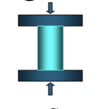
- Compressive Strength Test: Measures resistance to axial crushing loads applied lengthwise along a cylindrical sample.
- Diametral Tensile Strength Test: Measures tensile strength of brittle materials. A flat, disc-shaped specimen is compressed laterally across its diameter. The applied vertical compressive load converts into a uniform transverse internal tensile stress acting perpendicular to the load axis. Brittle materials fracture by splitting vertically along the tensile plane before compressive crushing occurs.
- Flexural Strength Test (Three-Point Bending Test): Measures deformation resistance of a rectangular beam supported at both ends under a central vertical load. The top surface of the specimen experiences compressive stress while the bottom surface experiences tensile stress.
- Clinical Cavity Classifications and Internal Stress Patterns:
- Class I Cavities: Experience predominantly direct vertical compressive stresses under occlusal loading.
- Class II Cavities: Experience complex mixed stresses. While occlusal surfaces receive compressive forces, gingival margins experience lateral flexural and tensile stresses. Brittle materials with low tensile strength (such as dental amalgam) are prone to marginal fracture in Class II cavities.

- Stress Concentration and Microcrack Mechanics:
- Stress Concentration: Magnification of localized stress around structural irregularities such as sharp internal angles, surface notches, void porosities, or internal microcracks.
- Cavity Design Rule: All internal line angles in cavity preparations must be rounded to distribute stresses evenly and prevent crack initiation.
- Crack Orientation Dynamics:
- Microcracks aligned perpendicular to applied tensile forces are pulled open, causing rapid crack propagation and failure.
- Microcracks located within compressive stress zones (e.g., top surface during flexural bending) are pushed closed, suppressing crack propagation.
- Microcracks located within tensile stress zones (e.g., bottom surface during flexural bending) are pulled open, leading to sudden catastrophic fracture.
