Locking & Limited Slip Differential Operation
The locking differential is a type of special traction differential.
It locks both side gears together, delivering the same amount of torque to both wheels.
There are various designs of locking differentials: mechanical, electrical, or air-locking systems.
Some are driver-controlled, while others operate automatically.
Most locking differentials are aftermarket add-ons, though some are available as factory options.
Off-road and racing vehicles commonly use locking differentials for improved traction.
Full Locking Differential Operation
Straight/Reverse Driving
When the vehicle is moving straight ahead, both wheels are locked and the axle shafts transmit torque equally to both wheels.
Turning Corners
When torque is no longer supplied to the wheels, a full locking differential functions like a ratchet, allowing the inner wheel to turn slower than the outer wheel.
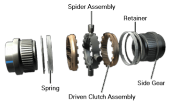
To unlock the full locking differential, the pressure between the spider and clutch assembly must overcome the spring pressure.
The spring pressure keeps the clutch assembly in contact with the spider assembly.
When the clutch and spider pressure overcomes the spring pressure, the clutch assembly unseats from the spider assembly.
This ratcheting action repeats as the vehicle turns corners, allowing smooth operation despite the locked condition.
Locking
As the vehicle straightens out from a turn, the pressure between the clutch assembly and spider assembly lessens.
Spring pressure forces the clutch assembly to seat against the spider assembly, restoring full locking, which distributes engine torque equally to both wheels.
If torque is applied during a turn, the full locking differential engages.
When engaged, the vehicle will push straight ahead or toward the outside of the turn due to the locked axles.
Automatic Locking Operation
Straight Driving
When the vehicle is moving straight ahead, the automatic locking differential functions like an open differential.
The differential transmits torque to both wheels, allowing normal straight-line driving.
Turning Corners
When the vehicle is turning, one clutch slips to allow the wheels to rotate at different speeds.
If one wheel has less traction, the differential transmits a greater portion of torque to the wheel with more traction.
Under normal conditions, both axles receive equal torque from the differential.
When one wheel slips, some of the torque is lost to the wheel with less traction.
Governor
When the speed difference between the wheels exceeds 100 RPM, the governor rotates.
Centrifugal force causes the flyweight to contact the latching bracket, stopping the governor from rotating.
This action slows the cam plate, causing it to move out of its detent position.
The ramps of the cam plate ride on the ramps of the cam side gear, compressing the left clutch pack.
Compression of the clutch pack moves the cam plate and cam side gear toward the right side of the differential case.
This movement pushes the thrust block, compressing the right-hand side gear clutch pack.
At this point, the differential is locked, transferring torque effectively to both wheels.
Governor Rotates
A decrease in torque, such as when slowing down the vehicle, will unlatch the governor.
The cam plate returns to its detent position.
The governor rotates, and the differential is unlocked, allowing normal differential action.
Driver-controlled Differential Locking
Electronic Locking - Unlocked
The electronic locking differential functions like an open differential when the vehicle is moving and the differential is in the unlocked mode.
In this mode, it allows the wheels to rotate at different speeds for normal driving and turning.
Activated
When the vehicle’s speed is less than 3 mph, the differential lock switch is ON.
The wheel speed difference is less than 50 RPM, and the transfer case indicator switch shows 4Lo.
The automatic transfer case shift control module sends a signal to energize the coil assembly, engaging the differential lock.
Locked
When the coil assembly is energized, a magnetic field allows the outboard locking differential ball bearing plate to rotate slower than the inboard ball bearing plate and the differential case.
The speed difference causes the ball bearing to move along the ramps, separating the two ball bearing plates.
The differential lock pins are pushed through the differential case toward the locking differential side gear.
When the lock pins are engaged, the locking differential side gear is locked to the differential case, causing it to rotate at the same speed as the ring gear.
Cable Locking - Unlocked
The cable locking differential functions like an open differential when the vehicle is moving and the differential is in the unlocked mode.
In this mode, the wheels can rotate at different speeds for normal driving and turning.
Engaged
When the driver moves the lever of the cable locker, a shift fork on the differential cover operates the internal shift fork inside the differential.
This action locks the side gear to the differential case, eliminating differential action and forcing both wheels to rotate together.
Disengaged
To disengage the cable, the driver of the vehicle moves the shift lever to the unlocked position.
Air Locking - Unlocked
The air locking differential functions like an open differential when the vehicle is moving and the differential is in the unlocked mode.
In this mode, the wheels can rotate at different speeds, allowing normal driving and turning.
Activated
When the air locker is activated, air pressure from the compressor moves a shift collar inside the differential case.
This locks both side gears to the differential case, eliminating differential action and forcing both wheels to rotate together.
Deactivated
When air pressure is exhausted, spring pressure forces the shift collar back to the open differential mode.
Limited Slip Differential
The limited slip differential (LSD) allows some slip between the two axle shafts, enabling smooth turning.
When one wheel slips, the LSD sends torque to the wheel with more traction and limits torque to the wheel with less traction.
This helps keep the vehicle moving when one drive wheel is on ice or stuck in mud.
There are various designs of limited slip differentials, including:
Hydraulic
Helical gear
Clutch pack
Viscous clutch
Cone clutch

Fluid Additive
Clutch-type limited slip differentials typically require a fluid additive with a friction modifier.
The friction modifier prevents the friction plates from locking during turns.
Glycerol mono-oleate is a common example of a friction modifier used in these differentials.
Hydraulic Limited Slip Differential Operation
Step 1
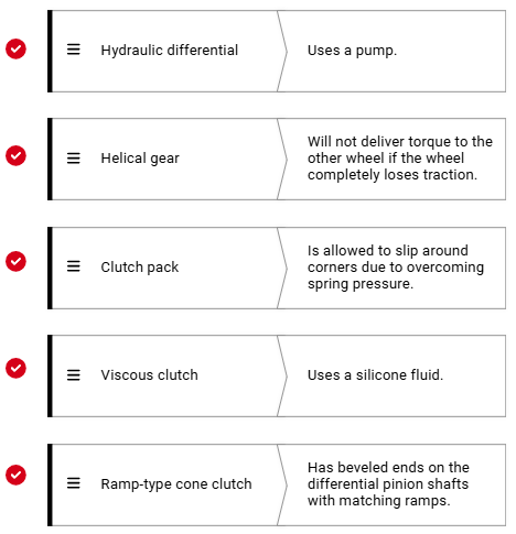
In a mechanically operated hydraulic limited slip differential, the inner rotor of the pump is splined to one axle shaft, and the pump housing is attached to the differential case.
When one axle rotates faster than the other, the hydraulic pump spins faster, causing pressure to build up in the system.
This pressure engages the clutch pack, transferring torque to the wheel with more traction.
Step 2
The pressure from the hydraulic pump causes the piston to apply the clutch.
As the clutch engages, the piston presses against the steel plates, which are splined to the carrier case, and the friction plates, which are splined to one of the differential side gears.
This action locks the side gear to the differential case, transferring torque to the wheel with traction.
Step 3
Because one side gear is locked to the carrier case, the pinion gears cannot rotate on the pinion shaft.
This causes the other side gear to rotate along with the carrier case.
As a result, the system limits the amount of slip between the two axles, improving traction.
Step 4
Because the axles are splined to the side gears, the axles rotate with the differential case.
The wheels turn at nearly equal speeds due to the limited slip allowed by the clutch pack.
Step 5
When the axles rotate at the same speed, the hydraulic pump no longer delivers pressure to the clutch pack.
This allows the differential to function like an open differential.
The pressure output of the pump depends on the speed difference between the axles.
Helical Gear Limited Slip Differential Operation
Step 1
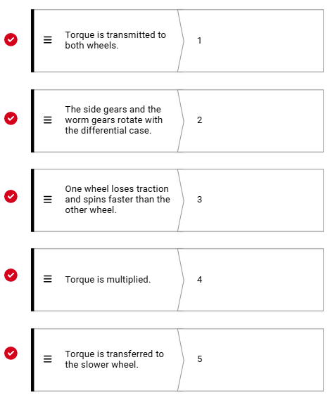
The helical gear differential functions similarly to an open differential when torque is transmitted to both wheels.
It allows the wheels to rotate at different speeds during turns while still distributing torque.
Step 2
The helical gear differential uses two helical-style side gears along with several worm gears.
The worm gears rotate on a parallel axis to the side gears.
The worm gears also mesh with the side gears, allowing torque to be distributed between the wheels.
Step 3
If one wheel loses traction, the differential multiplies torque from the spinning wheel.
Step 4
The differential transfers torque to the slower rotating wheel.
Step 5
When one wheel loses traction completely, the differential cannot supply torque to the other wheel.
Any non-open differential should be tested according to the manufacturer’s procedure for the specific vehicle application.
Clutch Pack Limited Slip Differential Operation
Step 1
This design uses two multi-disc clutch packs.
The clutch packs are located between the side gears and the differential case.
They help transfer torque to the wheel with more traction while allowing some slip for smooth turning.
Step 2
The friction plates are splined to the side gears, and the steel plates are splined to the differential case.
A spring separates the two side gears.
Depending on the design, the spring may be a multiple coil spring or an S-spring, which pushes the side gears apart inside the differential case, preloading the clutch packs.
Step 3
When one wheel loses traction and spins faster than the other, the opposite pinion gear still drives its axle with torque transferred from the carrier.
The amount of torque transferred depends on spring tension, which causes the friction and steel plates to try to lock together.
Because the friction plates are splined to the side gear and the steel plates are splined to the differential case, the side gears rotate with the differential case, transferring torque to the wheels.
Step 4
When traction is unequal between the drive wheels, the clutch pack attempts to hold the side gears to the differential case.
Because the axles are splined to the side gears, the axles rotate with the side gears, transferring torque to the wheels with traction.
Step 5
When the vehicle is turning, the spring pressure is low enough to allow some slippage of the clutch plates.
Friction modifiers in the special additive help the clutch slip smoothly without chattering, ensuring quiet and controlled operation.
Viscous Clutch Limited Slip Differential Operation
Step 1
When the left and right axles are rotating at the same speed, the differential delivers power to both wheels equally.
Step 2
When one wheel has less traction than the other, the axles rotate at different speeds.
Step 3
Because of the speed difference between the axles, the differential shears the silicone fluid, developing heat and fluid expansion.
Step 4
The expansion of the silicone fluid clamps the multi-disc clutch.
Step 5
The clutch directs torque to the wheel with the most traction.
Cone Clutch Limited Slip Differential Operation
Step 1
When the external and internal cones are pressed together, friction causes the side gears and differential case to rotate together.
Step 2
When the vehicle is moving straight, spring pressure forces the cone clutches against the internal cones in the differential case.
Step 3
When the vehicle is turning, the differential action of the pinion gears overcomes the spring-induced friction.
This allows the wheels to rotate at different speeds, enabling smooth cornering
Step 4
Some cone clutch differentials have beveled ends on the differential pinion shafts with matching ramps in the carrier.
If one wheel loses traction when torque is applied, the ramps force the side gears apart.
This action pushes the cones into firmer contact with the differential case, increasing torque transfer to the wheel with traction.
Step 5
The ramps apply pressure to both of the clutches, causing both axles to turn at nearly the same speed, giving the best traction.