Chapter 3(1/2) - Building Construction and Systems for Fire Investigators
Part 1 – Objectives, Building Systems, Design, Loads, and Materials
Knowledge Objectives
After studying this chapter, you should be able to:
Identify the design, construction, and structural elements of buildings and describe their effect on fire development, spread, and control. (NFPA 1033: 4.2.2; 4.2.3; 4.2.5; 4.2.8, pp. 43–46)
Identify and describe types of building construction. (NFPA 1033: 4.2.2; 4.2.3, pp. 46–52)
Assess the structural integrity of construction assemblies during a fire. (NFPA 1033: 4.2.3, pp. 52–54)
Identify the components of heating, ventilation, and air conditioning (HVAC) systems and describe their potential involvement in fire. (NFPA 1033: 4.2.3; 4.2.8, pp. 54–56)
Explain the impact of passive fire protection systems on fire investigation. (NFPA 1033: 4.2.3, pp. 56–58)
Describe the considerations when documenting a passive fire protection system. (NFPA 1033: 4.2.8, p. 58)
List the types of fire protection systems.
Identify and describe the components of common fire alarm and detection systems. (NFPA 1033: 4.2.8, pp. 58–66)
Identify and describe the operational characteristics of common fire alarm and detection systems. (NFPA 1033: 4.2.8, pp. 58–66)
Identify and describe the operational characteristics of water-based fire suppression systems. (NFPA 1033: 4.2.8, pp. 69–79)
Identify and describe the components of fire suppression systems. (NFPA 1033: 4.2.8, pp. 69–84)
Identify and describe the operational characteristics of non-water-based fire suppression systems. (NFPA 1033: 4.2.8, pp. 79–84)
Describe how to document fire protection systems. (NFPA 1033: 4.2.8, p. 84)
Skill Objectives
There are no skills in this chapter.
Introduction
A structure’s design, materials, and construction type influence how a fire develops and moves. These features may have a positive effect by containing fire within a compartment or a negative effect by allowing it to spread from the area of origin.
Proper analysis of fire growth and movement requires an understanding of:
Building construction
Building systems
Fire protection systems
The definitive fire patterns left by a fire
Building Systems Overview
Many modern construction practices developed from analysis of past fires, including catastrophic conflagrations around the beginning of the twentieth century. More than half of modern code requirements relate to fire protection.
A major cause of severe structural fire damage is the failure to contain or confine the fire. Construction principles aim to keep fire within its room, area, or structure of origin. When a fire leaves its room of origin, the route is commonly an unprotected or improperly protected opening or a construction defect rather than a failure of a protection system. Examples include:
Open doors
Unprotected penetrations through fire resistance-rated walls or ceilings
Openings made for building or utility services
Fire beginning in an interstitial space does not receive the same protection as fire developing inside a compartment. These concealed gaps may exist around the building frame, behind interior walls and the exterior façade, or above a ceiling beneath the next floor or roof deck, such as a cockloft (NFPA 921, Section 7.2.2.5). Fire can develop there without detection and move rapidly without effective barriers.
Investigators need to understand the building’s active and passive systems, including:
Manual and automatic fire detection
Fire suppression
Heating, ventilating, and air conditioning (HVAC)
Utilities
Building compartmentation
The use and location of fire resistance-rated assemblies
Knowing where these systems were installed and how they operate helps determine their performance, their effect on the fire, and whether alterations or failure indicators are present. Apparent system failure does not necessarily mean a fault or deliberate interference occurred; the fire may simply have overwhelmed the system.
An operating HVAC system can move smoke and fire through a structure. Determine the system’s condition and operating status at the time of the fire. Mechanical and electrical inspectors or engineers can assist with unfamiliar systems.
Design, Construction, and Structural Elements
A building’s response to fire or explosion depends on factors such as:
Construction type
The integrity and fire performance of structural elements under a fire load
Active and passive fire protection systems
The number and arrangement of doors, windows, and other openings
A broken window or opened door introduces oxygen that can greatly increase fire size and speed. Exterior winds can rapidly drive fire down unprotected corridors. The investigator must therefore consider environmental and mechanical conditions that existed during the incident, including ventilation.
The building’s interior layout, interior finishes, services, and utilities can also influence fire origin, development, and spread.
Figure 3-1 – Typical single-family dwelling

Figure 3-1 identifies the following structural components:
No. | Component | No. | Component |
|---|---|---|---|
1 | Foundation wall | 20 | Stair partition casing |
2 | Frost wall | 21 | Attic insulation |
3 | Wall footing | 22 | Partition studs |
4 | Perimeter drain | 23 | Second floor joists |
5 | Rafter | 24 | Finish flooring |
6 | Collar beam | 25 | Wall insulation |
7 | Ridge board | 26 | Cripple stud |
8 | Roof sheathing | 27 | Damper control |
9 | Window header | 28 | Ash door |
10 | Attic joist | 29 | Hearth |
11 | Box beam | 30 | Post or column |
12 | Exterior wall stud | 31 | First floor joist |
13 | Wall sheathing | 32 | Subfloor |
14 | Corner bracing | 33 | Basement partition |
15 | Exterior wall plate | 34 | Stair stringer |
16 | Box sill | 35 | Tread and riser |
17 | Sill | 36 | Cleanout door |
18 | Wall stringer | 37 | Concrete floor slab |
19 | Header | 38 | Granular fill |
Building Design
Fire development and spread in a building largely result from radiant and/or convective heat transfer. Within a compartment, important variables include:
Room size and shape
Ceiling height
The placement and area of doors and windows
Interior finishes and furnishings
HVAC systems
Fuel packages and location
Compartmentation is a central fire-safety design strategy: a structure is divided so fire can be limited to a particular area. Investigators must be prepared to encounter varied construction techniques and building materials that may affect fire spread.
Tip
Become familiar with not only the most common building designs and construction, but also less-common styles of buildings or compartments, such as atriums, stadiums, and tunnels, that could have different impacts on fire spread. Special designs may also incorporate special materials.
Building Loads
Loads are forces acting on a structure. Building design accounts for temporary or movable live loads, including people, furniture, furnishings, equipment, machinery, wind, snow, and rainwater. It also accounts for the dead load that remains in place, including structural components, roof coverings, and mechanical equipment.
A structure may become unstable or fail when the applied load exceeds its design parameters. Possible causes include:
Extreme wind or snow
Additional contents or stock
Added mechanical equipment, such as HVAC or elevator equipment
A large concentration of people in a limited area
Water introduced during firefighting
Structural Changes
Structural changes may be deliberate, as during renovations, or may result from the fire itself. Fire can damage supporting elements until they can no longer carry their intended loads.
Always conduct an exterior examination to:
Identify fire-related structural compromise and potential collapse hazards
Preserve existing evidence
Interpret exterior fire damage
Locate all possible entry and egress routes so an area being processed has at least two ways out
Identify the building’s utilities
These considerations also apply during the initial interior survey before scene processing begins.
Room Size
Room geometry—including height, width, and especially the distance between walls—affects fire development. With comparable fuel and ventilation, a smaller room reaches flashover sooner than a larger room. Because flashover can spread fire beyond the room of origin, room size is important when reconstructing fire development. In a very large room, heat transfer may never become sufficient to produce flashover.
Compartmentation
This subdivision of a structure into separate sections or units can limit fire spread. Fire commonly spreads horizontally beyond its compartment of origin through doors, windows, unprotected openings, and wall penetrations. Stairways, utility chases, and shafts provide possible vertical routes.
Interstitial and Concealed Spaces
Concealed and interstitial spaces occur in most buildings and can carry fire beyond the original compartment. Interstitial spaces commonly lack fire stops, allowing movement behind wall finishes, within exterior-wall cavities, or above ceilings. Missing fire stops may permit vertical spread. Where fire stops are present, examine whether they remained intact and stopped or limited spread.
Failure to recognize a concealed space can produce an incorrect interpretation of fire patterns. Depending on the building, these spaces may contain:
Fire sprinklers
Early-detection devices
Fire stops
Codes may permit some concealed spaces when they are built from noncombustible material. Using them to store combustible items can promote fire spread and is often prohibited.
Planned Design Versus “As-Built” Conditions
When possible, obtain the building’s floor plan from the owner, fire department, or building department having jurisdiction. Building-department records can show whether permits were issued for interior or exterior alterations. However, walls, wiring, and mechanical systems are sometimes changed without permits.
Original plans frequently differ from what was actually constructed. Determine whether available plans accurately represent the “as-built” structure. Undocumented changes may be identified through:
Examination of the fire scene
Comparison with similar houses constructed by the same contractor in the same project
Witness interviews
Occupant photographs
Building Materials
The chemical composition, thermal conductivity, and density of building materials influence ignition, fire growth, and fire speed. Plastics and other synthetic materials used in modern construction can significantly increase heat-release rates.
Thermoplastics may change from solids to liquids and then to ignitable gases. While burning, they can form flaming drips and pools that create drop-down damage and patterns. Thermoset plastics instead pyrolyze directly into ignitable gases and generally do not drip or flow. At the area of origin, identify the plastic involved so a melted thermoplastic pool is not mistaken for suspected ignitible liquid.
Table 3-1 — Building Materials
Characteristics | Influencing Factors |
|---|---|
Ignitability | Minimum ignition temperature; minimum ignition energy; time/temperature relationship for ignition |
Flammability | Heat of combustion; average and peak heat release rate; time to peak heat release rate; mass loss rate; air entrainment |
Thermal inertia | Reaction to heating; ease of ignition; fuel load |
Thermal conductivity | Good conduction versus poor conduction |
Toxicity | Quantity and types of gases produced by a material while burning |
Physical state and heat resistance | Temperature at which the material changes phase; amount of heat required to ignite the material in its different phases |
Orientation, position, and placement | Different burning characteristics exhibited by the materials, depending on whether they are vertical or horizontal; flame spread ratings, which can be obtained through a Steiner Tunnel Test (see NFPA 921, Section 7.2.3.7.2) |
Orientation affects burning behavior. Carpet normally lies horizontally on a floor; placing it vertically on a wall greatly increases flame spread associated with the carpet.
Orientation, Position, and Placement of Loads
Fuel load includes all combustible contents within a building, space, or fire area—including interior finishes and trims—and may be expressed in heat units or as an equivalent weight of wood (NFPA 921).
Do not overlook the orientation, position, or placement of fuel packages. Their location and installation influence how they burn and how quickly fire progresses. For example, a trash can 3 feet (0.9 m) from a burning desk presents a different spread potential from one immediately beside the desk. Interior finishes and furnishings likewise influence fire speed and intensity.
A 2-inch (5-cm) by 4-inch (10-cm) piece of oak is compared with a lower-density 2-inch (5-cm) by 4-inch (1-cm) piece of balsa wood. The oak burns much slower and creates less char.
Steiner Tunnel Test
The Steiner Tunnel Test, ASTM E84, establishes flame-spread indexes used in fire and building codes. Many materials evaluated in the tunnel are not designed or intended for use as wall or ceiling coverings. A tested product’s classification may not represent its actual behavior if it is installed in an orientation or application for which it was not designed. Such an installation would not be an acceptable interior finish under the applicable codes.
Interior-finish requirements depend on occupancy type and size. If an assembly is unrated, there is no standard fire-test information showing how that assembly will react. Code violations involving interior finishes can produce devastating outcomes and have contributed to incidents with multiple fire deaths. Recognizing improper finishes may help explain rapid fire development or loss of life.
Occupancy
Determine whether the building’s use or occupancy classification changed at any time. Occupancy describes the intended use of a structure, such as residential or commercial. A change can introduce fuel loads the original fire-protection systems were not designed to handle. A change of occupancy is often accompanied by changes to the structure and systems, putting the “as-built” structure at even greater variance from the original plans. Egress and active or passive fire-protection safeguards may consequently be inadequate.
For example, a home-improvement store may have additional rack-storage sprinkler protection in its paint section. If the paint is moved elsewhere without extending that protection, the standard sprinkler protection in the new location may be overwhelmed by the fuel load presented by aerosols, paints, thinners, and strippers.
Chapter 15, Analyzing the Incident, provides additional discussion of failure analysis and how it can affect fire spread in a building.
Tip
It is important to determine whether a building’s occupancy classification has changed since it was built or renovated. Different occupancies require different fire protection systems depending on their load, contents, and storage configuration.
Part 2 – Types of Building Construction
Construction methods vary throughout the world; this chapter focuses on the types most common in the United States. Determine and document construction type from the building’s structural elements. Also record:
Structural components
Breaches
Structural changes
Other conditions that could affect structural integrity or fire spread
Tip
A wood wall stud is commonly called a 2 by 4, reflecting the nominal lumber measurement. The actual dimension of the 2 by 4 [2 × 4] is 1¾ (44.5 mm) by 3½ inches (88.9 mm), which is the dimensional lumber measurement.
Ordinary Construction
In ordinary construction, NFPA 921 describes exterior walls as masonry or other noncombustible materials. The floor, roof, and partition framing are wood assemblies that use braced- or platform-frame methods. NFPA 220, Standard on Types of Building Construction, classifies ordinary construction as Type III.
The term ordinary reflects this construction type’s use in many different buildings. Fire spread can be affected by:
Open vertical shafts
Combustible materials
Multiple ceilings
Figure 3-2: Ordinary construction is used in a wide variety of buildings.
Wood-Frame Construction
NFPA 220 classifies wood-frame construction as Type V. Exterior walls and load-bearing components use wood or other combustible materials, most commonly in residential and commercial buildings of limited size.
Floor joists and vertical supports are generally spaced 16 inches (0.4 m) on center. Nominal vertical members may measure:
2 inches (5 cm) by 4 inches (10 cm)
2 inches (5 cm) by 6 inches (15 cm)
These members alone offer little fire resistance. Flames and hot gases can penetrate gaps between joists or studs and carry fire outside the area of origin.
Sheathing can provide additional resistance. Examples include:
Gypsum board
Lath and plaster
Mineral tiles
Even non-fire-rated sheathing may provide some resistance. A fire-rated wall, however, may still conduct heat to the underlying members or combustible materials on its opposite side.
A masonry veneer does not change the construction classification when the supporting frame is wood. Fire-resistive membranes applied according to ASTM testing standards can provide wood-frame construction with up to a 2-hour fire resistance.
Table 3-2 — Ordinary Construction Versus Frame Construction
Ordinary Construction | Frame Construction | |
|---|---|---|
Exterior walls | Masonry or noncombustible material | Wood |
Interior walls | Wood assemblies; Platform or braced frame assembly | Wood assemblies; Platform or braced frame assembly |
Platform-Frame Construction
Most modern wood-frame buildings use platform framing. The walls for each level rest on a platform or floor, so each platform acts as a fire stop against floor-to-floor vertical spread. Because the barriers are combustible, fire may eventually overcome them.
Important areas of concern include:
Concealed spaces in soffits, which are the horizontal undersides of eaves or cornices
Vertical openings made for utilities
Figure 3-3 — Platform-frame construction.

Tip
Checking the floor or roof to see whether it is spongy does not ensure safety with modern lightweight construction.
Balloon-Frame Construction
Unlike platform framing, balloon framing uses exterior wall studs that continue uninterrupted from the foundation wall to the roofline. Codes have long required fire stops in the resulting vertical channels. Fire stops may consist of:
Wood boards
Noncombustible material, such as insulation, filling the void
Proper fire stops can give the building fire performance similar to platform-frame construction. Missing fire stops can permit uninhibited vertical spread or ignition caused by burning material falling from the attic. Fire stops may also be removed when wiring, HVAC equipment, or other services are installed.
Open vertical channels can produce rapid upward extension. Open connections between floor joists and the vertical channels also make horizontal extension likely. These channels may allow burning debris to fall and combustion gases to convect downward.
Consequently:
More extensive burning may occur at the upper level than where the fire originated.
Fire may emerge remotely from its origin.
Fire may bypass one floor and reach another.
Investigators must identify every possible route of fire travel.
Figure 3-4: Balloon-frame construction.

Tip
Fires that have burned in balloon-frame walls destroy the structural integrity of the building. Collapse is a serious threat.
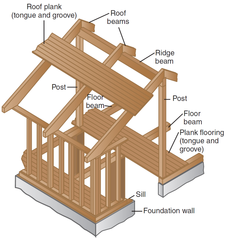
Plank-and-Beam Construction
This method uses large beams supported by posts. Examples of beam dimensions include:
4 inches (10 cm) by 10 inches (25 cm)
5 inches (12.5 cm) by 12 inches (30 cm)
The beams are spaced more widely than conventional framing—typically 4 or 6 feet (1.2 or 1.8 m) on center. Floor decking has a minimal thickness of 2 inches (5 cm) and is generally tongue-and-groove, which helps limit fire spread.
Other characteristics include:
Few concealed spaces
Exterior finish that has no structural value
Large spans of unsupported finish material that may result in failure of structural sections, with large frame members left standing
Large interior areas with exposed combustibles that can support flame spread
Figure 3-5 — Plank-and-beam construction has a limited number of concealed spaces.
Post-and-Frame Construction
A visible skeleton of large fitted timbers distinguishes this method, which is similar to plank-and-beam construction. In typical barn construction, the posts provide most of the support and the frame provides a surface for attaching the exterior finish.
Figure 3-6: Post-and-frame construction.

Heavy Timber Construction
Structural members are unprotected wood with a smallest dimension of 6 or 8 inches (15 or 20 cm). Floor assemblies use 2-inch (5-cm) thick, tongue-and-groove end-matched lumber, and no concealed spaces are permitted.
Building codes require bearing walls in heavy timber construction to have a 2-hour rating. Fire spread may still be rapid because of:
Wood-frame components
Open spaces
Large areas of interior combustibles
Figure 3-7: Heavy timber construction has exterior walls that consist of masonry construction and interior walls, columns, beams, floor assemblies, and roof structures that are made of wood.
Contemporary log homes use specially milled logs for their exterior walls and many structural elements. The interior structure is generally 2-by-4 wood framing, although the finishes are commonly made to resemble the milled-log exterior.
This mismatch between the visible finish and the underlying construction may confuse an investigation involving rapid fire spread or structural failure. Large open interior spaces are another hazard because they facilitate fire spread.
Insurance companies helped develop mill construction as an early heavy timber method after recognizing the need to reduce major factory-fire losses.
Typical features include:
Masonry exterior walls
Heavy timber columns and beams
Walls generally assigned at least a 2-hour fire rating
Rated doors in interior walls between compartments
No concealed spaces, improving the building’s fire-resistive performance
Protection of vertical openings to limit fire passage
Fire sprinkler systems
Wall scuppers that drain water and reduce water damage
Alternative Residential Construction
Residential construction also includes manufactured housing and steel-framed systems in addition to site-built wood framing.
Manufactured housing is constructed in one or more sections. While being transported, a section measures at least:
8 feet (2.4 m) wide
40 feet (12.2 m) long
The sections are transported to the site and assembled there, where they can be 320 ft² (29.7 m²) or larger. Another form is built on a wheeled steel frame for transportation and is often called a mobile home.
Manufactured homes are the least expensive structures to build. Some incorporate house-like features such as:
Steeper-pitch roofs
Residential-size windows
Covered decks
Figure 3-8: Manufactured home.
Manufactured homes contain four principal components or subassemblies:
Chassis
Floor system
Wall system
Roof system
The chassis generally has two longitudinal steel beams braced by steel cross members. These members receive vertical loads from the walls, roof, and floor. Once onsite, the loads transfer to stability devices, which may consist of piers or footings, or to a foundation. Steel outriggers cantilevered from the outside of the main beams bring the chassis to approximately the full width of the structure.
Since the mid-1970s, mobile homes built to the U.S. Department of Housing and Urban Development (HUD) Standard have used more substantial construction than earlier units.
HUD-approved construction generally includes:
Wood studs
Interior finishes, most often gypsum wallboard
Metal, vinyl, or wood exterior siding
Stronger, more solidly built roof systems, often with gable- or hip-style rooflines
An asphalt paper/shingle roof covering over oriented strand board (OSB) or plywood attached to rafters or wood trusses
A wall system bonded into a complete unit between the roof and floor systems by steel ties
Older pre-HUD units commonly use:
2-inch (5-cm) by 2-inch (5-cm) exterior wood studs
Asphalt paper serving as a vapor barrier
Aluminum siding attached directly to the studs
Interior wood paneling
No insulation in the wall voids
A minimal flat wood-frame roof with a steel exterior skin
Minimal construction and the absence of fire-resistant interior finishes allow faster, more intense fire spread. Newer manufactured homes use gypsum wallboard on walls and ceilings and include code-required smoke alarms. Their fire dynamics are more similar to those found in site-built homes, and fire spread is not as rapid as in pre-HUD homes.
Early detection devices wired to house power reduce the chance of a large fire and lower the risk of death or injury.
A modular home is also called a system-built or prefabricated home. Multiple sections are produced in a controlled offsite facility using technology similar to newer site-built homes. At the selected site, the sections are joined into one residence using a crane or trucks.
Unlike manufactured homes, modular homes have neither axles nor a transport frame. They are placed on a foundation supplied by the contractor. Designs may be single-floor or multilevel and can be customized. Fires in modular homes have burn tendencies similar to those of site-built wood-frame homes.
Steel-framed residential construction is becoming more common in:
Site-built systems
Panelized systems
Pre-engineered systems
It has many characteristics of wood framing but does not add combustible framing material. Extreme heat can nevertheless cause the steel frame to lose structural capacity.
Figure 3-9: Steel will begin to lose its strength at temperatures of 1000°F (537°C).
Manufactured Wood and Laminated Beams
Laminated beams are made by gluing or laminating many wood planks into a single structural beam with performance similar to solid wood. These members are generally intended only for interior use and are commonly called glulam beams.
They behave like heavy timber until failure. Weather exposure reduces their load-bearing ability. During an investigation, document:
The size of each individual member
The overall beam dimensions
Wood I-beams have smaller dimensions than floor joists and can therefore burn through and fail sooner than dimensional lumber. Openings cut through the vertical center portion, or web, for utilities may reduce the structural integrity of the web. Gypsum-board protection is required to help delay collapse during a fire.
Lightweight wood trusses are similar in design to other trusses. Individual members may be joined with:
Nails
Staples
Glue
Metal gusset plates, also called gang nail plates
Wooden gusset plates
Truss failure can occur when gusset plates fail before the wood members are burned through. When one member fails, the remaining members assume additional loads and may become stressed, which may cause failure of the entire truss.
Rating of Wood-Frame Assemblies
A wall receives a fire rating by being covered with a noncombustible finish, commonly gypsum board. Even then, heat may conduct through the assembly to the combustible members beneath it.
Actual field installation can differ from the construction used during fire-integrity testing. Poor installation may therefore cause a rated wall to fail sooner than its tested rating suggests.
Noncombustible Construction
This construction is used primarily for commercial, industrial, and high-rise buildings. Its materials do not contribute to the fuel load. Examples include:
Brick
Stone
Metal
Non-reinforced concrete
Metal Construction
Exposed metal is common in unfinished spaces and may fail in as little as 3 minutes during flashover. Fire-rating tests may not predict actual scene performance because real fires are unpredictable and can differ substantially from laboratory conditions.
Investigators should examine:
Building conditions
Interior finishes
Ventilation effects
Whether exposed metal contributed to earlier-than-expected failure
Ductile metals such as steel deform before failure. This deformation may occur in two ranges:
Elastic range: The material changes shape under load and then returns to its original shape without losing strength when the load is removed.
Plastic range: Stress beyond the elastic limit produces permanent deformation, although the material may continue carrying the load.
Elongation or deformation in either range can produce building collapse or damage.
Table 3-3 — Steel Versus Masonry/Concrete
Material | Factors |
|---|---|
Steel | Can conduct electricity. Good conductor of heat. Loses its ability to carry a load well below the maximum temperatures encountered in a fire. Can distort, buckle, or collapse as a result of fire exposure. The amount of distortion depends on factors such as the heat of the fire, duration of exposure, physical configuration, and composition of the steel. |
Masonry and concrete | Will generally absorb more heat than steel, due to its mass. Good thermal insulator. Does not heat up quickly, and does not transfer heat through itself as easily as steel. Masonry and concrete will carry a load much longer at a given temperature when compared with steel. |
Concrete and Masonry Construction
Mass, high density, and low thermal conductivity give concrete and masonry inherent fire resistance. These materials are strong under compression but weak under tension, and structural failure often begins at connection points.
Failure may result from:
Heat transfer through the concrete or masonry
Surface spacing, which exposes the reinforcement to fire temperatures
Failure of steel connections between components at temperatures well within those found in structure fires
Figure 3-10: Concrete is noncombustible and provides thermal protection around steel reinforcing rods.
Part 3 – Construction Assemblies, Walls, Doors, and Structural Protection
Construction Assemblies
Walls, floors, ceilings, and similar completed units are assembled from manufactured components. These units may or may not have a fire-resistance rating. A door is one component within a larger door assembly.
Even unrated assemblies usually provide some resistance to fire or smoke. Because assemblies interact, failure of one can contribute to failure of another and affect fire growth and spread.
An assembly is designed to function as a complete unit. Its integrity during a fire depends on it being manufactured, installed, and maintained as intended. Conditions that can compromise performance include:
Fire doors blocked open between compartmentalized fire areas
Unprotected utility openings through fire-rated walls
Other holes left in walls
Missing ceiling tiles
Ceiling tiles that were not clipped down
Ductwork passing through an area without the required fire and/or smoke dampers
These defects can allow for the passage of fire.
Fire-resistance ratings come from specific tests conducted under defined conditions. An actual structure fire may be more severe than the test and may cause an assembly to fail before its assigned hourly rating. After a fire, examine the complete rated assembly for flaws in any of its components.
Floor, Ceiling, and Roof Assemblies
These assemblies are a major concern because they are among the first building elements to fail after structural members are exposed to fire. Failure can involve:
Collapse
Deflection
Distortion
Heat transmission
Fire penetration
Performance is influenced by:
Type of structural element
Protection from the elements
Span
Load
Beam spacing
Water introduced during firefighting adds weight and can contribute to failure. Utility penetrations are also common and are required to be sealed when they pass through a fire-rated assembly, although this is often not done.
Floor assemblies are tested for fire spread from below, not from above. Roof stability can affect both firefighting operations and fire dynamics, making collapse potential a vital scene concern.
Structural elements are not intended to retain their strength under fire conditions. Protective materials such as gypsum wallboard delay their direct involvement. Once that protection fails and the structural elements are exposed, their load-bearing capacity decreases.
Walls
Walls may limit both fire and smoke spread, but they are constructed to many standards and may or may not be fire-resistance rated or load bearing.
Figure 3-11: A. A load-bearing wall provides structural support. B. A non-load-bearing wall supports only its own weight.
Utility penetrations through fire-rated wall assemblies must be sealed. Different wall systems serve different protective functions. Fire walls separate buildings or compartmentalize the interiors of large buildings to restrict fire spread while creating a fire-resistance-rated, structurally stable division. Fire barriers resist the passage of fire and smoke; a gypsum-board fire barrier uses Type X gypsum wallboard. Smoke barriers are continuous vertical or horizontal membranes—such as wall, floor, or ceiling assemblies—constructed to restrict smoke movement (NFPA 921).
Fire walls and fire barriers normally do not have to meet the same requirements as smoke barriers unless they are also intended to perform that function.
An unrated assembly may still provide some fire resistance. Its lack of a rating means that no test was done for that type of wall, ceiling, or floor component, so no established failure time exists.
Assemblies incorporating smoke damper systems are intended to restrict smoke passage. Their openings may or may not also be protected against fire passage.
During an investigation, examine interior walls to determine:
Which walls are load bearing
Whether supporting elements were removed, creating structural stress and possible collapse
Whether walls were intended to resist fire, smoke, or both
Whether fire passed through an unsealed penetration
Fire walls and smoke barriers are constructed of specific materials that have been tested and proven to prevent the passage of smoke or fire.
Contractors may install lines or other components through compartment separations without closing the openings as required by fire or building codes.
Doors
Doors can determine whether fire remains confined or spreads through a structure. They may be fire rated or non-fire rated and may be made from several materials.
Every opening in a fire-rated wall or partition requires a rated door and its complete associated assembly. Rated components include:
Frames
Hinges
Closures
Latching devices
Glazing, when provided and permitted
Fire doors may be constructed from:
Solid wood
Steel
Steel with an insulated core of wood or mineral material
Their insulating value supports egress, especially in multistory buildings, and helps protect combustibles near the unexposed side of the opening from autoignition. The door must be closed to serve as an effective barrier against smoke, heat, and fire.
A door placed in a fire resistance-rated wall assembly should be installed as a complete fire-protection-rated door assembly. Its hourly rating depends on the fire wall’s rating and is generally lower than the rating of the wall system.
Figure 3-12 — A fire door has a label indicating its classification and rating.
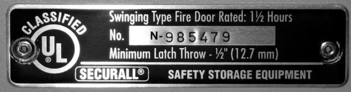
The label identifies the door’s classification and rating. Visible markings on the example include:
CLASSIFIED UL
Swinging Type Fire Door Rated: 1½ Hours
No. N-985479
Minimum Latch Throw - ½" (12.7 mm)
SECURALL SAFETY STORAGE EQUIPMENT
For the assembly to retain its rating, its hinges, closures, latching devices, and glazing must all operate properly. NFPA 80, Standard for Fire Doors and Other Opening Protectives, provides further information.
During a fire investigation:
Determine whether a fire door was propped open with doorstops or other objects before the fire.
If an approved magnetic hold-open device was used, determine whether activation of the fire alarm released the door and whether the door then closed and latched securely.
If a door was propped open, determine whether that was normal practice or an unusual condition.
Consider whether firefighters propped the door open during suppression operations.
Inspect for holes, penetrations, or modifications that prevented the door from conforming to its intended design.
Concealed Spaces
Penetrations commonly provide concealed access for:
HVAC systems
Plumbing
Electrical systems
Computer lines
Telephone lines
Other building functions
Each penetration must be sealed to maintain the rating of the wall or floor it passes through. Openings added after construction are not always properly sealed and may allow fire or smoke to move from one protected area into another.
Construction Materials
Unprotected structural steel loses strength at high temperatures and should be protected from exposure to the heat produced by building fires. Protection methods include:
Encasement in poured concrete
Calcium-silicate board systems
Gypsum board systems
Spray-on fireproofing
Intumescent coatings
A less-common method fills hollow structural members so the fill acts as a heat sink and slows the steel’s temperature rise.
Reinforced concrete can be used as a protective coating. Its fire resistance is affected by:
The concrete’s density
Aggregates
Moisture content
Wood encasement may or may not maintain reasonable structural integrity during fire exposure. Important variables include:
Wood-member size
Wood moisture content
The presence of fire retardant intended to delay ignition and reduce combustion
Part 4 – Heating, Ventilation, Air Conditioning, and Air Handling Systems
Heating, Ventilation, and Air Conditioning Overview
Residential and commercial heating, ventilation, and air-conditioning systems may provide heat, cooling, or both. Depending on the settings and the ambient-air temperature, the same system may deliver either heated or cooled air.
When examining a fire scene, investigators often need to analyze:
The types of systems present
Their components
How they perform
Whether they played any role in the fire
Heating Systems
Heating systems produce heat in several ways. Investigators often need to analyze whether a heating system:
Served as an ignition source
Contributed to the fire in another way
Was not involved
Components of Heating Systems
Fuels
Heating equipment may use electricity or a combustible fuel. Natural gas is typically piped into a building. Propane is normally delivered to a tank that can be found onsite. Other possible fuels include:
Fuel oil
Wood
Coal
Other unique types of fuels
All-electric heating systems, including electric baseboard systems, do not rely on a combustible fuel supply. Building gas systems are discussed further later in the chapter.
Devices
Furnaces may be powered by electricity, gas, oil, or solid fuel. Most fuel-burning furnaces other than electric units use a vent or chimney to discharge combustion products. Furnaces may be:
Central air furnaces
Furnaces mounted in the structure’s floor
Furnaces mounted on the wall
Boilers are normally made of cast iron or steel. Boilers run on either hot water or steam and may be powered by propane, natural gas, fuel oil, or solid fuel. Safety devices monitor conditions such as pressure, low water level, and temperature to help prevent a fire or explosion.
Radiant or convective heaters may use flat panels installed in walls, floors, or ceilings. Heat may come from electric elements or from water circulated through pipes.
Stoves may burn wood, wood pellets, or coal. Their fire chamber is contained within a metal or soapstone enclosure, and combustion products are discharged through a vent or chimney.
Fireplaces are commonly constructed of masonry and may burn solid fuel or gas. They normally provide no control over the amount of incoming air. Factory-built fireplaces are metal units that use liners, refractories, and insulation to protect the surrounding wooden enclosure. They may also include a gas igniter, an air-circulation mechanism, or both.
Electric heating units include:
Baseboard heaters
Permanent wall- or floor-mounted room heaters
Central forced-air systems
Chimneys and Vents
Chimneys and vents carry exhaust from heat-producing devices to the outside. Masonry chimneys and unlisted metal smokestacks are not tested prior to installation.
Factory-built chimneys, by contrast, are complete assemblies tested to established safety standards. Factory-built vents have specific types and designations corresponding to the furnaces or other appliances for which they are intended.
Controls and Safety Devices
Controls and safety devices are required in heating systems to enhance safety by preventing improper or unexpected operation. They include:
Pressure switches, which may monitor draft or air flow, fuel pressure on oil and gas systems, or water or steam pressure
The high-temperature limit, a heat sensing switch that remains closed during normal operation and opens when a preset temperature is sensed
Door switches, which confirm that required doors are in place
Flame sensors, which verify that a flame is present when fuel is being supplied and help prevent an accumulation of unburned fuel gas
Controls that start or stop a burner in response to changes in demand
Flame rollout detectors, which shut down a gas-fired heater if flame rolls out of the combustion chamber, potentially because of improper draft or soot buildup
Control thermostats, which regulate operating temperature; for example, a thermostat may activate a circulating fan after a heat exchanger reaches a set temperature
Installation, Use, and Maintenance
Numerous codes and standards address the installation of heating devices and their fuel supplies. Manufacturer instructions may also be necessary when evaluating a specific installation.
Important installation considerations include:
Appliance placement
Venting and associated controls
Fuel supply
Air required for combustion and cooling
Depending on the circumstances, the investigator may need to determine the installation history and details of a heat-producing appliance. Its use and maintenance must also be evaluated against the manufacturer’s instructions for safe operation.
Heating Systems as Potential Causes of Fire
The presence of a heating device in the area of origin does not by itself establish that the device ignited the fire. A proposed heating-device cause must be tested against other applicable hypotheses as required by NFPA 921.
Testing may show that a device:
Could not produce enough heat to ignite nearby combustibles
Was not functioning at the relevant time
Can be eliminated from consideration for another reason
A qualified specialist may be needed to examine a heating device and identify the particular failure mode that could have contributed to a fire.
When a heating device is located at the origin, consider whether:
The appliance was operating at a normal temperature but was against or near fuel within a distance that allowed sufficient heat to cause the device to ignite. If so, determine whether the appliance could produce enough heat during normal operation to cause ignition.
A fault or failure caused the device to exceed its normal temperature, heating or igniting nearby material.
The device was installed or used outside the manufacturer’s intended use or applicable code requirements. Examples include a chimney installed without proper clearances or a stove or furnace supplied with improper fuel.
Under normal circumstances, the investigator should not attempt to disassemble a heating appliance to determine whether an internal failure occurred.
Related guidance appears in:
Chapter 5, Legal Considerations for Fire Investigators, regarding spoliation
Chapter 9, Identification, Collection, and Preservation of Physical Evidence, regarding collection of heating devices for examination
Chapter 14, Cause Determination, regarding potential fire causes involving heating devices
Air Conditioning and Air Handling
Components
When both systems are present, air-conditioning equipment commonly shares components with the heating system. A condenser coil, often outside the building, removes heat from the refrigerant. The refrigerant is then pumped to the circulation system.
In a system combined with a furnace, an evaporator coil uses the cooled refrigerant to cool air leaving the furnace before the air enters the building.
In both furnaces and air conditioners, an air handling unit includes:
A blower
An evaporator coil, when present
A filter or filters
Other system components
The unit sends air through supply ducts to occupied areas. Return vents draw air from conditioned spaces back to the furnace through a return plenum. The return pathway may instead use a plenum located between a drop ceiling and the upper floor or beneath a raised floor area.
Commercial air-movement systems may be considerably more elaborate. Air handlers may be installed:
In an equipment room
On a roof
On the ground
Ductwork may contain smoke detectors connected to the building fire alarm system and automatic dampers intended to limit the spread of fire and smoke. Codes may require larger systems to shut down when the fire alarm activates.
Some systems use smoke exhaust fans. Others pressurize selected building areas when an alarm activates to keep combustion products from entering refuge and egress areas.
Investigation
HVAC systems can contribute to the spread of fire and smoke. Heat, smoke, and toxic combustion products may enter the system for several reasons and circulate to other parts of the building, including plenum spaces, whether or not the blower was operating when the fire occurred. Ducts can also serve to supply fresh air—that is, an oxygen supply—to a fire, thereby supporting continuing combustion.
When analyzing fire- and smoke-spread scenarios, consider the presence and layout of the HVAC system and ductwork. Determine whether supply or return ductwork:
Delivered oxygen to the fire
Spread fire or smoke into other compartments
Affected occupants
Influenced the fire patterns found at the scene
Also determine whether components such as dampers were maintained and functional.
In larger buildings, assess whether air pressure against egress doors slowed or prevented occupant escape and whether smoke handling systems adequately protected occupants during evacuation.
Part 5 – Passive Fire Protection Systems
Part of a fire investigator’s work is determining whether a building was provided with passive fire protection and how that protection affected the incident.
Fire resistance-rated wall and floor assemblies create compartmentalized areas intended to control fire spread. These assemblies may take the form of:
Occupancy separations
Fire partitions
Fire walls
They are intended to keep fire, high temperatures, and flue gases within the compartment of origin while assisting firefighting and evacuation.
Determine whether any passive fire protection system failed and, if it did, how and why. Pay particular attention to damage that may have contributed to fire growth. Possible reasons for failure include:
Improper design
Inadequate installation
A change in occupancy and its associated hazards
Breaches in compartment walls or damage to applied coatings after the system was initially installed
Design and Installation Parameters of the System
When passive fire protection is present, evaluate whether each system and/or component influenced the fire’s evolution. Consider:
Which codes, guides, standards, and manufacturer instructions were in effect when the building was constructed
Whether an update may have been required to bring the system up to the most current code
Analyze the protection provided at door openings, including:
The door’s fire rating
Door frame
Door hardware
Construction surrounding the door
Evaluate windows in protected openings, including:
Type of glass
Glass thickness
Number of panes
Opening mechanisms and hardware
Frame
Construction surrounding the window
Examine ductwork penetrations through fire-rated walls, partitions, floors, and ceilings to determine their effect on the fire’s evolution. If smoke and/or fire dampers were required, determine whether they operated as required.
Examine every penetration for compliance with applicable:
Codes
Standards
Manufacturer instructions
Examination at Fire Scene
During the origin and cause determination phase, examine whether each passive fire protection system:
Was assembled properly
Impeded fire and smoke as expected
Failed prematurely
Table 3-4 — Considerations for Passive Fire Protection Systems
Component | Considerations |
|---|---|
Penetrations | Were they properly sealed? |
Joint systems | Did the system fail by not resisting the passage of fire as expected by its fire rating? Was joint material securely in or near the joint for the entire length of the component? Did the building code contain exceptions for requiring fire-rated joint systems? |
Fire doors | Were all necessary components included in the assembly? Did the closing device perform properly? An examination of the door label should be recorded if available. |
Fire windows | Were the glass and glazing the proper thickness? Was wire glass required or not? Was the framing appropriate for the window rating? |
Duct and transfer openings | Were any fire dampers, smoke dampers, fire/smoke dampers, and/or ceiling radiation dampers required? If so, did they operate as required when activated by fire, smoke, or automatic activation? Examine the actuating device/method to ensure that it operated as needed. |
Fireblocking and draftstopping | Did the structure require fireblocking or draftstopping in combustible concealed spaces? Was the fireblocking or draftstopping installed in the correct locations? Was the material used appropriate for the rating, and was it the proper thickness? |
Documentation and Data Collection
Documentation is important both for recording a passive fire protection system and for understanding any role it may have played in the fire. The investigator may review:
Design plans
Design specifications
As-built drawings
Equivalencies or alternative levels of protection approved by the authority having jurisdiction
Building and fire permits
Invoices for work performed on the system
Measurements
Diagrams and/or photographs
Maintenance records
Inspection records
Testing records
Document any occupancy changes that occurred after the original installation and determine whether the passive fire protection remained suitable for the current occupancy and fuel load.
The actual installation may differ significantly from the permit plans if an occupant made changes that are not reflected in the permit materials. Consult local code officials when modifications or installations found in the structure do not appear to comply with the code or permitted work.
Code Analysis
Fire investigators need to be familiar with applicable codes and know where to find installation requirements for passive fire protection systems. Relevant sources may include:
Building codes
Fire codes
Property maintenance codes
NFPA 101, Life Safety Code, if adopted by the authority having jurisdiction
Localized code amendments
In addition, it is a good idea to consult with the local building official and fire prevention staff.
Permit applications and/or building permits can provide dates indicating which codes may have been in effect when the passive fire protection system was installed. Both the name of the code and its specific edition are important when determining whether the installation met the requirements in force at that time.
Building codes address matters including:
Type of construction
Fire resistance-rated construction
Requirements for glass and glazing, gypsum board and plaster, and other materials
References to ASTM and Underwriters Laboratories
Design Analysis
Approved construction documents may contain:
Drawings
Specifications
Design calculations
Floor plans
Details
Cross-section elevations
Schedules for the work
If computer modeling or calculations are used to assess the passive fire protection system’s performance, the evaluation will likely require data concerning the thermal properties of the walls, ceilings, and floors.
Testing and Maintenance
Determine whether periodic testing or examination was required for the passive fire protection system, including fire prevention inspections. The building owner may be required to maintain the system by ensuring that it is not damaged or breached.
Part 6 – Active Fire Protection Systems and Fire Alarm Systems
Active Fire Protection Systems
Active fire protection systems fall into three general categories:
Fire alarm systems, including detection and notification appliances
Water-based systems
Fire suppression systems
These systems can provide analytical information that helps an investigator determine:
When and where a fire started
How the fire progressed
How system activation and operation affected the fire
System performance may contribute to the formation and testing of hypotheses concerning:
Origin
Cause
Fire spread
It is important to understand, document, and preserve fire protection systems. Technical specialists are often needed during documentation and analysis to prevent the destruction of critical data.
Fire Alarm Systems
Survival in a structure fire depends on the time between:
The fire starting
Occupants realizing that there is a fire
Occupants leaving the building
A properly designed, installed, tested, and maintained fire alarm system improves occupants’ chances of survival by detecting fire early and alerting them to take action.
A fire alarm system can provide direct notification to supervising stations, which then contact public safety answering points (PSAPs) and initiate the appropriate response without waiting for an individual to report the emergency. Some alarms are monitored directly by a PSAP. This alert will expedite the emergency response and, in many instances, may help limit property damage and potentially save a life.
System Components
A fire alarm system connects components and devices that produce audible and visual signals after activation, alerting occupants to a fire emergency and prompting a response.
Its three basic component groups are:
Control unit
Initiating devices
Notification appliances
Primary and secondary power supplies, initiating device circuits, notification device circuits, and alarm reporting services are associated with the control unit.
Initiating devices such as smoke and heat detectors may respond automatically to a fire condition and, through the control unit, initiate an alarm. A manual fire alarm box requires a person to operate it.
Notification appliances provide warnings that prompt occupants to react. Examples include:
Bells
Horns
Strobe lights
Alarm reporting services send signals by telephone or radio to supervising stations.
General System Operation
System operation begins when:
An initiating device automatically detects or reacts to a fire condition, or
A building occupant discovers the fire and manually initiates the alarm
The initiating device sends a signal to the fire alarm control unit, which activates the notification appliances. Many systems also transmit the alarm information to an onsite or offsite monitoring location, where operators receive the signal and take the appropriate action.
Modern commercial fire alarm systems often interface with building control, building management, and fire protection systems. These interfaces may initiate additional life-safety operations, including:
Starting fans to pressurize stairways, elevator shafts, and vestibules
Closing smoke dampers and doors to compartmentalize the building
Capturing elevators and moving them to predetermined floors
Unlocking certain doors to permit safe ingress and egress
Some fire alarm technology dates back 50 years or more. Even the oldest and most basic systems can provide information that is useful during an investigation. When an alarm activates, the FACU can provide information as simple as a marked light with a location identifier, such as the floor number, along with the type of device activated.
Modern FACUs can provide even more comprehensive information. Graphic and touch screen units can display the building footprint and/or alphanumeric readouts showing:
Device type
Type of alarm signal
Floor
Exact location of the device on that floor
Understanding basic system operation will greatly assist a fire investigator in interpreting the information available after a fire.
Key Components of Systems
Fire Alarm Control Unit
Two types of fire alarm control units (FACUs) remain in use:
Conventional technology
Addressable technology
Conventional technology has existed for more than 50 years and provides only basic information, performance, and monitoring capabilities. It remains useful in small buildings with few alarm-system devices, where locating the event does not require extensive travel through the building.
Addressable technology uses state-of-the-art computer and circuit technology to provide extensive event information to first responders. It can also:
Monitor system integrity for conditions that could inhibit the system or its components from operating properly
Interface with other building fire protection and life-safety systems
Fire alarm control units generate three types of output signals:
Alarm signal
Alerts occupants to a fire emergency with the expectation that they will leave the building
Notifies the supervising station
Initiates any other predetermined action necessary for life safety
Trouble alarm signal
Notifies a responsible party—usually the building engineer or maintenance personnel—that the fire alarm system has an integrity problem
Possible problems include:
Ground faults
Breaks in system wiring
Power or component failure
Communications problems
Device removal
Supervisory alarm signal
Notifies a responsible party—usually the building engineer or maintenance personnel—that the system’s normal ready status has changed
Possible status changes include:
Closure of electronically supervised fire suppression system control valves
High or low air pressure in dry-pipe sprinkler systems
Fire pump failures or abnormalities
Air or water temperatures outside the appropriate range
Low water level in a water tank
Water pressure that is too low or too high
Operation of associated fire protection equipment during nonfire conditions, such as starting a fire pump to exercise the pump and its associated components
Trouble and supervisory signals may be sent to a supervising station, which then notifies the building’s responsible party. If a predetermined period passes without communication with that person, the supervising station may notify the fire department.
To clear any of the three signals—and, in most cases, reset the FACU—the condition responsible for the signal must be investigated and resolved.
Power Supplies
The power supply is integral to the fire alarm unit and provides electrical power to the unit, system components, and system devices. Two power sources are required:
Primary power: Usually supplied by the local commercial power utility
Secondary or backup power: Usually supplied by rechargeable batteries
In some factory or industrial installations, natural gas, diesel fuel, or steam engine-driven generators serve as primary and secondary power sources.
The design capacity of both sources accounts for:
Current draw from all system circuits, components, and devices
Additional capacity as a safety margin
Additional capacity is especially important for the secondary source because code requirements establish the minimum time the system must remain operational on secondary power without failure.
The electrical circuit supplying power to the fire alarm control unit is not permitted to power other appliances.
Initiating Devices
Initiating devices interact with the fire alarm control unit through automatic or manual operation to activate the system.
Automatic operation. Initiating devices that respond to changes in the monitored environment include:
Fire detectors
Water flow detectors
Component monitoring devices
Fire detection devices may provide spot, line, or video coverage. Spot-type units place one sensing element—such as a smoke or heat detector—at a fixed location, usually on a ceiling, to protect a certain square footage area as determined by the manufacturer; some are installed in HVAC equipment or ductwork. Line-type devices follow a continuous route through the hazard by using electrically or thermally sensitive cable or a light beam. Video systems instead use high-definition cameras to detect pixel changes caused by smoke and flame generation.
Water flow and monitoring initiating devices are addressed later in the chapter.
Manual operation. A person can signal the fire alarm system by operating either of the following:
Manual fire alarm boxes
Electronic valve supervisory devices
Manual fire alarm boxes are also called manual pull stations. Although their basic operation is similar, differences include the type of signal generated and the actions required to operate the box. Coded and noncoded signaling are discussed later in the chapter.
A single action box requires one action.
A double action box requires two actions.
Operating an electronic valve supervisory device—also called a tamper switch—requires turning a wheel, handle, or other lever. Once it moves a specified distance, the device initiates a supervisory alarm.
Part 7 – Smoke, Heat, and Specialized Detection Devices
Smoke Detection
Smoke detectors initiate an alarm by detecting smoke particles produced by a fire rather than by detecting heat. Sufficient smoke must develop to trigger the detector before other detection systems operate, which makes smoke detectors life-safety devices.
Smoke detection uses two operating principles:
A radioactive element
Light that is obscured or scattered
Both types are reliable, although one may respond faster than the other depending on the fire and surrounding conditions. Detector selection should account for:
Environment
Building construction and design
Building contents and their burning characteristics
Room shape
Ceiling height
Airflow and ventilation
These factors determine which operating principle and device are best suited to the location.
Smoke Detectors Versus Smoke Alarms
People often regard smoke detectors and smoke alarms as the same device, but they are used differently. A smoke detector is installed mainly in commercial occupancies as a component of a fire alarm system. It relies on the fire alarm control unit for power and initiates an alarm through that unit. A smoke alarm is used mainly in residential occupancies and combines the sensing and sounding functions. It normally receives power from a house circuit, has battery backup, and is interconnected with the other installed smoke alarms.
With multi-station smoke alarms, activation of one device causes all connected alarms to sound. A single-station smoke alarm is a stand-alone unit powered only by a battery.
A smoke alarm may also be incorporated into:
A combination system in which security, medical, gas-detection, and fire signals report to a monitoring panel that notifies a supervising station
A complete fire alarm system that operates similarly to a commercial system
Tip
Smoke detectors and alarms remain some of the best early-warning life-safety devices, but they do have limitations. For example, spot-type smoke detectors cover only a certain area reliably and, over time, may become overly sensitive or undersensitive compared to their original design. This could be problematic because the level of sensitivity must be appropriate for the environment in which detectors are installed. If the devices are too sensitive, false alarms will happen; if they are not sensitive enough, detectors may not react rapidly enough to provide an appropriate warning.
Ionization Smoke Detectors
Ionization detection uses a small quantity of radioactive material and two electrically charged plates.
The radioactive material charges air particles inside the sensing chamber, making the air conductive.
Ionized particles attach to the oppositely charged plate, producing a small but measurable current.
When smoke enters, its particles attach to the charged air particles and reduce current flow between the plates.
The detector activates when current falls to a predetermined level.
Ionization detectors are normally spot-type devices. They are best suited to fires that quickly produce more flame than smoke, such as a burning piece of paper, and are the most common smoke alarms in residential occupancies.
Figure 3-13 — Principle of operation for an ionization smoke detector.
The diagram compares normal operation with smoke in the chamber. Under normal conditions, the galvanometer measures normal current flow between the charged plates. Smoke reduces that current, which the galvanometer shows as reduced current flow. The figure identifies the radioactive material that ionizes the air.
Photoelectric Detectors
A photoelectric detector uses a light source and a photoelectric-cell receiver positioned at an angle to one another inside the sensing chamber.
With no smoke present, the light beam does not strike the receiver.
When smoke or other particulate matter enters, the light source refracts off the particles into the receiver, initiating an alarm.
Photoelectric smoke detectors are usually spot-type devices. They respond more quickly to smoldering fires because those fires tend to produce larger smoke particles. Rapidly developing flaming fires produce smaller particles that do not refract as much light, which can delay alarm initiation. Photoelectric detectors are commonly used as fire alarm system components.
Figure 3-14 — Principle of operation for a light-scattering photoelectric smoke detector.
The no-smoke diagram shows the light beam passing through the chamber without reaching the photocell. In the smoke-filled diagram, smoke entering through the chamber openings scatters and reflects part of the beam into the photocell.
Air Sampling (Aspirating) Detectors
Air sampling smoke detection is one of the more sophisticated types of smoke detection in use. Also called aspirating detection, it uses a network of pipes with sampling holes to pull air continuously from the protected area into an analyzer.
By continuously sampling the air, the system can identify otherwise undetectable by-products produced as material breaks down during the precombustion stage—well before an occupant would notice them. The detection chamber may be inside or outside the protected room or area. Because it can receive air from several tubes, one system can cover more area than spot-type detectors.
Air entering the chamber is commonly analyzed by highly sensitive light refractions. Other methods, including chemical gas analysis, may also be used.
This approach is generally known as very early warning smoke detection because it can detect products of combustion well before typical spot-type smoke detectors. The system can provide progressively serious alarm levels:
A first-level alarm indicates an abnormal air characteristic.
A second-level alarm indicates that a fire may be present.
A final-level alarm indicates a fire in progress.
Air sampling systems may operate independently or as part of a broader fire protection strategy. They are commonly installed in high-value operations where concealed detection is important, maintenance access is limited, or critical processes cannot be disrupted. Examples include:
Historic buildings
Telecommunications facilities
Computer/server operations centers
Production facilities
Electrical substations
Semiconductor manufacturing facility clean rooms
Warehouses
Aircraft hangars
Textile mills
Atriums
Figure 3-15 — Air sampling smoke detection system.
A: The system control panel/analyzer.
B: The ends of sampling tubes, which contain small holes that capture air samples for analysis by the control panel/analyzer.
Projected Beam Detectors
These detectors send light across a protected area to a receiver. Smoke or another obscuration of the light source reduces the intensity reaching the receiver and initiates an alarm.
The beam can extend more than 300 feet (91 m) between the transmitter and receiver while covering a width of approximately 60 feet (18 m).
Projected beam detection is suited to places where spot detection would be impractical or ineffective, particularly areas with very high ceilings, including:
Atriums
Concert halls
Warehouses
Gymnasiums
Factories
Figure 3-16 — Principle of operation for a light-obscuration photoelectric smoke detector.
The figure shows an unobstructed beam traveling directly from a light source to a light sensor. When smoke enters the beam path, it scatters and obscures the light, reducing the amount that reaches the sensor.
Duct Smoke Detectors
Duct smoke detectors are installed on many commercial air distribution systems to sample air moving through building ductwork. Depending on the code authority having jurisdiction, activation may produce either:
An alarm signal
A supervisory signal
When particulate matter is detected in the airflow, the detector shuts down the associated air distribution unit. Without that unit moving air, smoke and toxic gases cannot travel as easily from one part of the building or one floor to another. This approach prevents or inhibits occupant exposure to potentially life-threatening products of combustion.
These detectors are not required on every air distribution system. Installation depends on airflow capacity, measured by the cubic feet per minute delivered by the unit. A detector must operate throughout the full range of air velocities, temperatures, and humidity expected at the installation.
Duct smoke detectors may be:
Mounted inside the ductwork
Mounted outside the unit and connected to sampling tubes inside the ductwork
Ganged together in front of an air duct intake
Many duct detectors are mounted above ceilings or too high to see, making it difficult to investigate their activation; inspect, test, maintain, and service the detectors; and, in some instances, reset the detector.
NFPA 72, National Fire Alarm and Signaling Code, requires a remote indicator when a detector is:
More than 10 feet (3 m) above the finished floor, or
In a location that is not readily visible
The indicator must identify the associated HVAC unit. Remote lamps or annunciation devices should be installed on a wall, ceiling, or as close to the detector as possible so first responders or maintenance personnel can locate it quickly.
Figure | What It Shows |
|---|---|
3-17 | Duct detector air sampling tubes are located inside the ductwork to capture air samples. |
3-18 | Duct detector mounted on an air duct line. |
3-19 | Remote indicator for a difficult-to-locate or concealed duct detector. |
Heat Detection
Heat detectors are among the oldest and most reliable fire-detection devices. They are useful in challenging environments where smoke detection may not be suitable, including:
Dusty locations with fluctuating temperatures
Locations where a fire will produce high heat output
Locations where detection speed is not the primary concern
They respond to either:
A predetermined fixed temperature
A specified rate of temperature change
Three operating principles—the fuel, hazard, and associated rate of fire development—determine whether fixed-temperature, rate-of-rise, or rate-compensation detection should be installed.
Fixed-temperature detectors operate when the sensing element reaches its rated temperature.
Rate-of-rise detectors measure temperature change over a fixed period.
Rate-compensation detectors react to predetermined air temperatures.
Most heat detectors are spot-type devices, although line-type detectors may be more appropriate for some hazards and environments.
Because they rely on fire-generated heat rather than smoke, heat detectors usually respond more slowly than other fire detectors, particularly smoke detectors. They are not life-safety devices and should not replace smoke detectors unless the reviewing authority having jurisdiction approves the substitution.
When heat detection replaces smoke detection, the reason is normally an ambient condition or environment that could cause a smoke detector to malfunction or activate inappropriately.
Radiant Energy–Sensing Fire Detection
Radiant energy–sensing detectors can operate without waiting for smoke or heat plumes. They monitor selected portions of the visible or invisible light spectrum produced by:
Flames
Sparks
Embers
They are well suited to manufacturing and industrial environments where non-fire-related sources of radiant energy are more common. These detectors commonly protect high-risk, high-value facilities where rapid and sensitive detection and remote detection of small fires are critical.
Detector selection requires careful evaluation of:
The environment
Fuel type
Nonfire radiant energy sources that could cause false alarms
Conditions that could prevent an alarm
Examples of protected locations include:
Petroleum processing, storage, and loading facilities
Print shops
Paint application facilities
Airplane hangars
Woodworking facilities
Textile mills
Museums
Ordnance facilities
Computer data rooms
Flame Detectors
These detectors respond to a selected part of the light spectrum. Operating ranges include:
Ultraviolet (UV)
Infrared (IR)
Ultraviolet/infrared (UV/IR)
Multiple-wavelength infrared
Dual UV/IR and multiple-wavelength IR detectors use two sensing elements. Both elements must detect the required light spectrum band before an alarm is triggered. Dual sensing improves recognition of an actual fire and reduces activation from nonfire radiant energy sources.
Radiant energy detectors require an unobstructed view of the protected area and must be close enough to receive sufficient energy to initiate an alarm. When the view or distance creates a problem, additional detectors are required to ensure complete coverage of the hazard area. Flame detectors may be designed and adjusted for different flames, flame intensities, or both.
Spark/Ember Detectors
These detectors are not fuel specific. They look for sparks or embers produced during manufacturing and are normally installed on, in, or near conveyor belts or duct lines where solid materials move through a process. In these locations, the possibility of a spark or ember starting a fire is high.
These detectors:
Operate in the infrared range
Are normally installed in closed, dark environments
Activate some type of suppression after detecting a spark or ember
Suppression commonly consists of a water spray nozzle connected to an ultra-high-speed water spray system.
Other Types of Detectors
Gas-sensing fire detection may be designed to detect a specific gas, any type of toxic gas, or various gases and vapors associated with processes utilizing hydrocarbons.
Available sensing technologies include:
Infrared
Semiconductor
Electrochemical
Catalytic beads
These systems protect commercial, industrial, and residential occupancies, including:
High-hazard environments
Off-shore oil and gas rigs
Oil, gas, and petrochemical facilities
Gas turbines
HVAC air intakes
Oil and gas wells
Enclosed air handling ductwork
A detector may be manufactured exclusively for gas sensing or as a combined gas/smoke detector. Inspection, testing, maintenance, and calibration are necessary to ensure proper operation.