Checking Voltage Drop
Limits of Resistance Test
A resistance test alone may not identify a faulty circuit.
This test does not show whether the circuit can support the necessary current to operate an electrical device.
Example:
A chafed wire with only one copper strand intact may still pass a resistance test when measured with a DMM set to ohms.
The ohm reading could appear normal and match that of an undamaged wire.
However, the damaged wire cannot carry enough current to properly power devices like a light bulb or motor.
Therefore, current testing is essential to verify a circuit’s ability to deliver adequate power.
Voltage Drop Testing
Identifies circuits with unwanted or excess resistance
Is needed as unwanted resistance may not be detected by measuring ohms with a DMM
Small losses in voltage can add up and affect the performance of electrical components.
Voltage Drop Readings
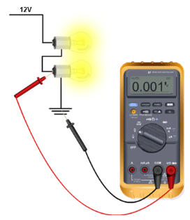
Series Circuit
May have multiple load devices
Allows each device to have a different resistance value
May display different readings if the voltage drop is measured across each device
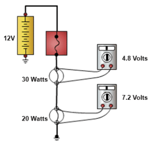
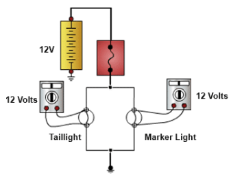
Parallel Circuit
The voltage drop across each parallel load device will always equal the source voltage
Resistance and current readings may differ in each branch, but the voltage drop will be the same for each load device
The total voltage drop of each branch will also equal the source voltage
Reasons to Check Circuits for Voltage Drops
Inoperative Circuits such as Dome Lights, Door Locks
Poor Performance of a Circuit such as Headlights, Starter Motor, and Charging System
Steps of Measuring
Step 1
Use the manufacturer’s service information to find the maximum allowable voltage drop for the circuit under test
The maximum allowable voltage drop is typically 200 millivolts (mV) on smaller gauge circuits and 500 millivolts (mV) on larger gauge circuits
Step 2
If applicable, turn on the digital multimeter, or DMM, using the ON/OFF button on the meter.
Step 3
Set the mode selector switch to the millivolts or the volts DC setting.
Step 4
Set the meter range to auto range, or select a low-voltage reading setting.
Step 5
Connect the black test lead to the COM, or negative, input jack of the DMM.
Step 6
Connect the red test lead probe to the volt/ohms/hertz, or positive, input jack.
Step 7
Connect the red test lead probe at the beginning of the circuit that is being tested.
Step 8
Next:
Connect the black lead to the end of the circuit being tested
Place the meter leads across the component being tested
Step 9
Now, activate the circuit by closing the switch, and it will now be operational. Any load items in the circuit should be operating. The circuit must be active for the DMM to measure the voltage drop.
Step 10
Finally:
Excessive voltage drops indicate unwanted resistance in the circuit
Connect the test leads in parallel with the ground circuit wire to test the ground side of the circuit