sanjai phy ia
 PHYSICS
IA
BY
SANJAI SMARAN.J
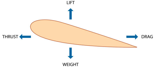
Aim
To observe how the lift and drag coefficient changes in every aerofoil .
Research Question
How does the shape of an aerofoil affect the amount of lift and drag produced?
Introduction
During the research of this topic I had seen many wing configurations present. Each wing configuration had a 2D shape named Aerofoil. Aerofoil is the 2D version of a wing that helps in the flight of the planes. I chose this topic because aeronautics is the most fascinating topic for me. In this document you will be seeing different aerofoil configurations and how does its configuration affect the lift and drag coefficient. The hypothesis has been depicted as graphs for better understanding.
Background information
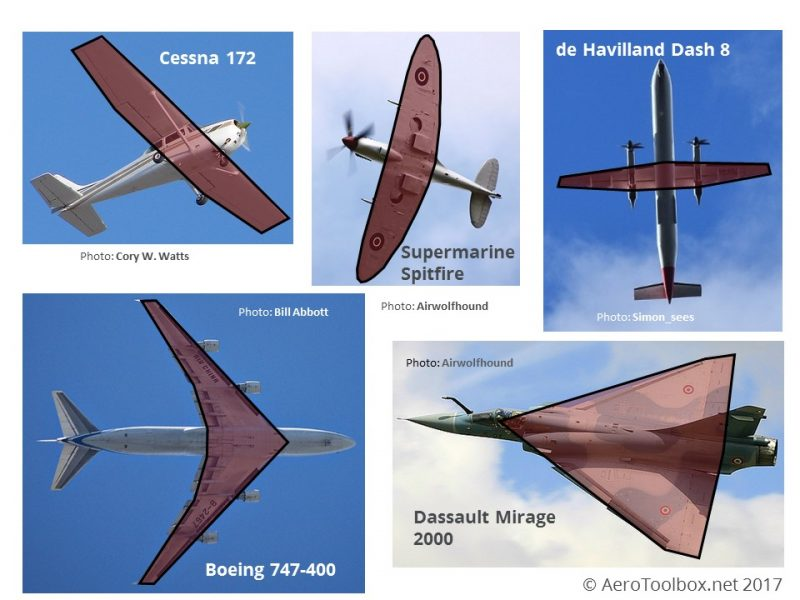
Wing Configurations
There are many wing configurations. For example there is:
- Elliptical wing
- Delta wing
- High wing
- Low wing
- Swept wing
Elliptical Wing
An elliptical wing is a wing platform whose leading and trailing edges each approximate two segments of an ellipse. Theoretically, the most efficient way to create lift is to generate it in an elliptical spanwise distribution across the wing.There is no inherent superiority to pure elliptical shapes, and wings with other platforms can be optimized to give elliptical spanwise lift distributions.
Delta Wing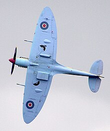
A delta wing is a wing shaped in the form of a triangle. It is named for its similarity in shape to the Greek uppercase letter delta (Δ).The delta wing form has unique aerodynamic characteristics and structural advantages. Many design variations have evolved over the years, with and without additional stabilizing surfaces. The long root chord of the delta wing and minimal area outboard make it structurally efficient. It can be built stronger, stiffer and at the same time lighter than a swept wing of equivalent aspect ratio and lifting capability. Because of this it is easy and relatively inexpensive to build—a substantial factor in the success of the MiG-21 and Mirage aircraft series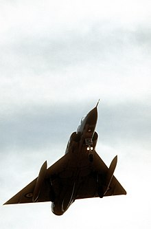
Swept wing
A swept wing is a wing that angles either backward or occasionally forward from its root rather than in a straight sideways direction. Swept wings have been flown since the pioneer days of aviation. Wing sweep at high speeds was first investigated in Germany as early as 1935 by Albert Betz and Adolph Busemann, finding application just before the end of the Second World War. It has the effect of delaying the shock waves and accompanying aerodynamic drag rise caused by fluid compressibility near the speed of sound, improving performance. Swept wings are therefore almost always used on jet aircraft designed to fly 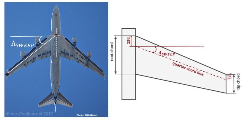 at these speeds. The term "swept wing" is normally used to mean "swept back", but variants include forward sweep, variable sweep wings and oblique wings in which one side sweeps forward and the other back.
There are three main reasons for sweeping a wing:
- To arrange the center of gravity of the aircraft and the aerodynamic center of the wing to coincide more closely for longitudinal balance
- To provide longitudinal stability for tailless aircraft.
- Most commonly to increase Mach-number capability by delaying to a higher speed the effects of compressibility (abrupt changes in the density of the airflow).

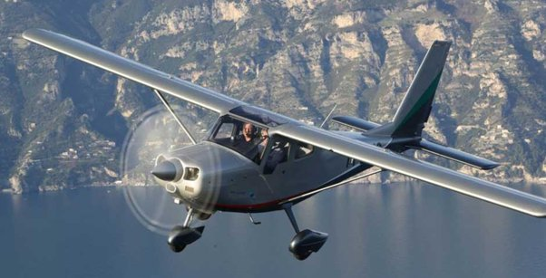
High Wing
High wing: mounted on the upper fuselage. When contrasted to the shoulder wing, it applies to a wing mounted on a projection (such as the cabin roof) above the top of the main fuselage of the aircraft.
Low wing
A low wing is one which is located on or near the bottom of the fuselage. Placing the wing low allows good visibility upwards and frees the central fuselage from the wing spar carry-through. By reducing pendulum stability, it makes the aircraft more maneuverable, as on the Spitfire; but aircraft that value stability over maneuverability may then need some dihedral. A feature of the low-wing position is its significant ground effect, giving the plane a tendency to float farther before landing.Conversely, this ground effect permits shorter takeoffs.
Types of Aerofoil
- Symmetrical aerofoil
- Cambered aerofoil
Symmetrical aerofoil
This is when the upper and lower half of the aerofoil are perfectly symmetrical in shape. The model of this aerofoil is : b 17 manufactured by boeing.
Cambered aerofoil
This is when the upper and lower half of the aerofoil are not symmetrical in shape at all.
Example model of this aerofoil is :Boeing 747 manufactured by boeing.
There are many manufacturers for aerofoils. One of the main manufacturers are Naca. One of the main models that I found while researching was the aerofoil Naca 2415. The black line in the middle of the aerofoil is called the cord line. Cord line is the specific angle needed for lift for the wing.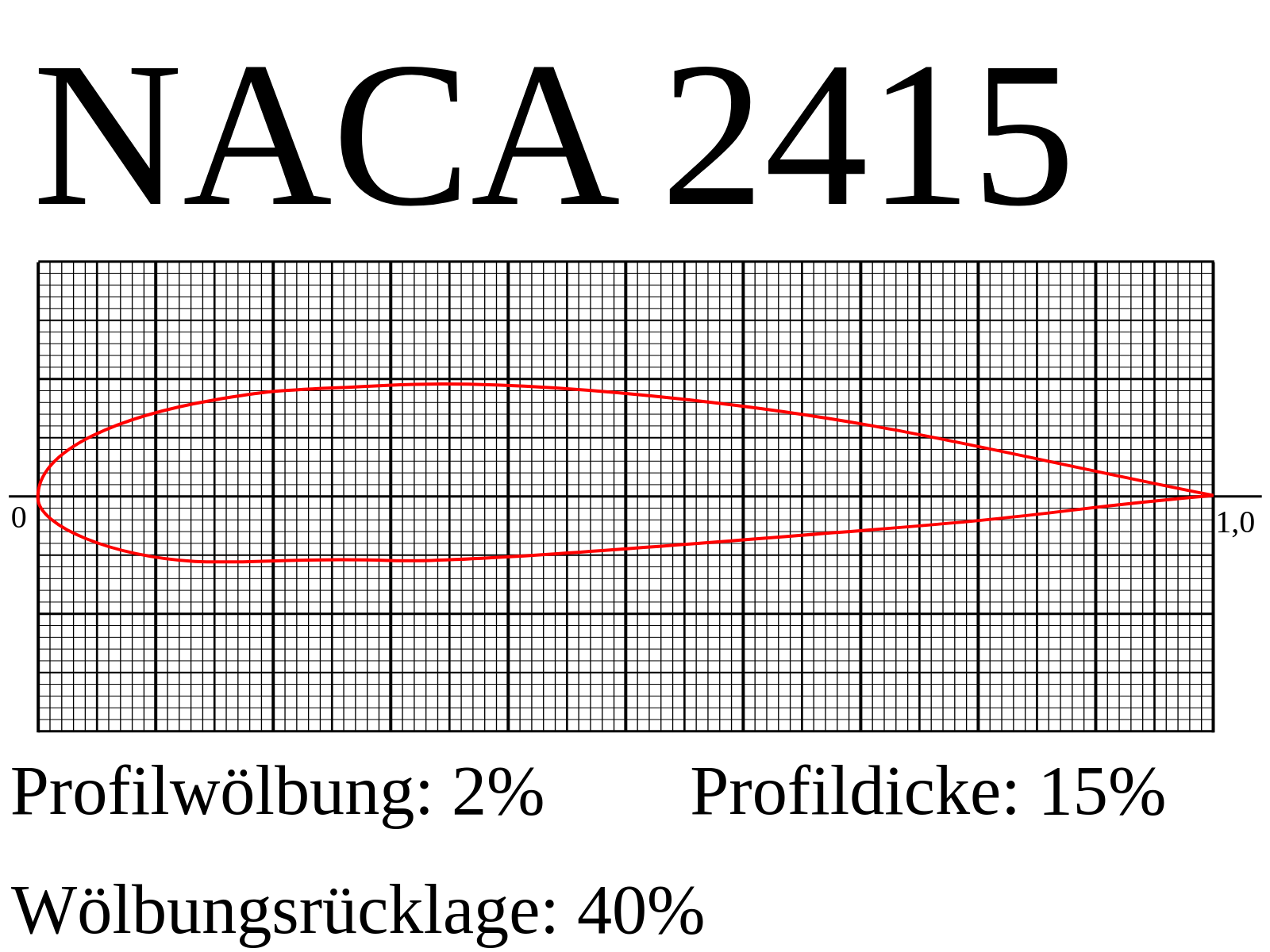
The line in the middle is the chord line. The chord line cuts the airfoil into an upper surface and a lower surface. If we plot the points that lie halfway between the upper and lower surfaces, we obtain a curve called the mean camber line.
The mean camber line is the asymmetry between the two acting surfaces of an airfoil, with the top surface of a wing commonly being more convex. An airfoil that is not cambered is called a symmetric airfoil.
The airfoil is considered to be symmetrical or uncambered when the upper section of the airfoil from the centerline mirrors that of the lower section, i.e., the upper and lower surfaces are identical. Symmetrical airfoil produces less lift than cambered airfoil.
Hypothesis
The change in camber of an aerofoil will affect the lift and drag coefficient.
Variables
Lift Coefficient
The lift coefficient (CL) is a dimensionless quantity that relates the lift generated by a lifting body to the fluid air density around the body, the fluid velocity and an associated surface area. A lifting body is a foil or a complete foil-bearing body such as a fixed-wing aircraft.
Drag Coefficient
The drag coefficient is a dimensionless quantity that is used to quantify the drag or resistance of an object in a fluid environment, such as air or water. It is used in the drag equation in which a lower drag coefficient indicates the object will have less aerodynamic or hydrodynamic drag. The drag coefficient is always associated with a particular surface area.
Data Collection
Now I am going to be taking a few aerofoils and compare bthe drag and lift coefficients. The aerofoils are:
- Naca 2414
- Naca 2421
- Naca 2415
- Naca 2412
Simulations for each aerofoil
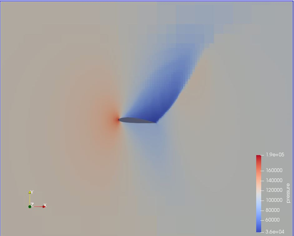
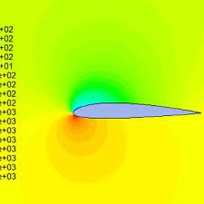
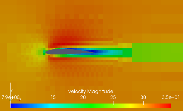
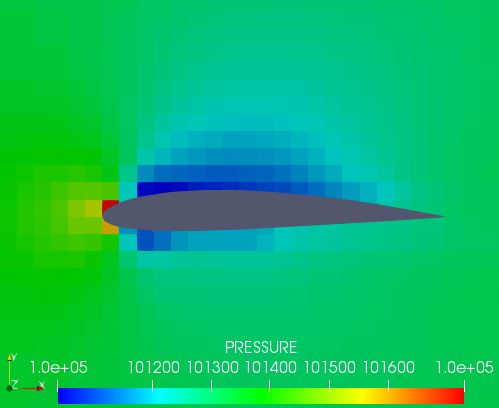
Here is the pressure and velocity profile for Naca 2414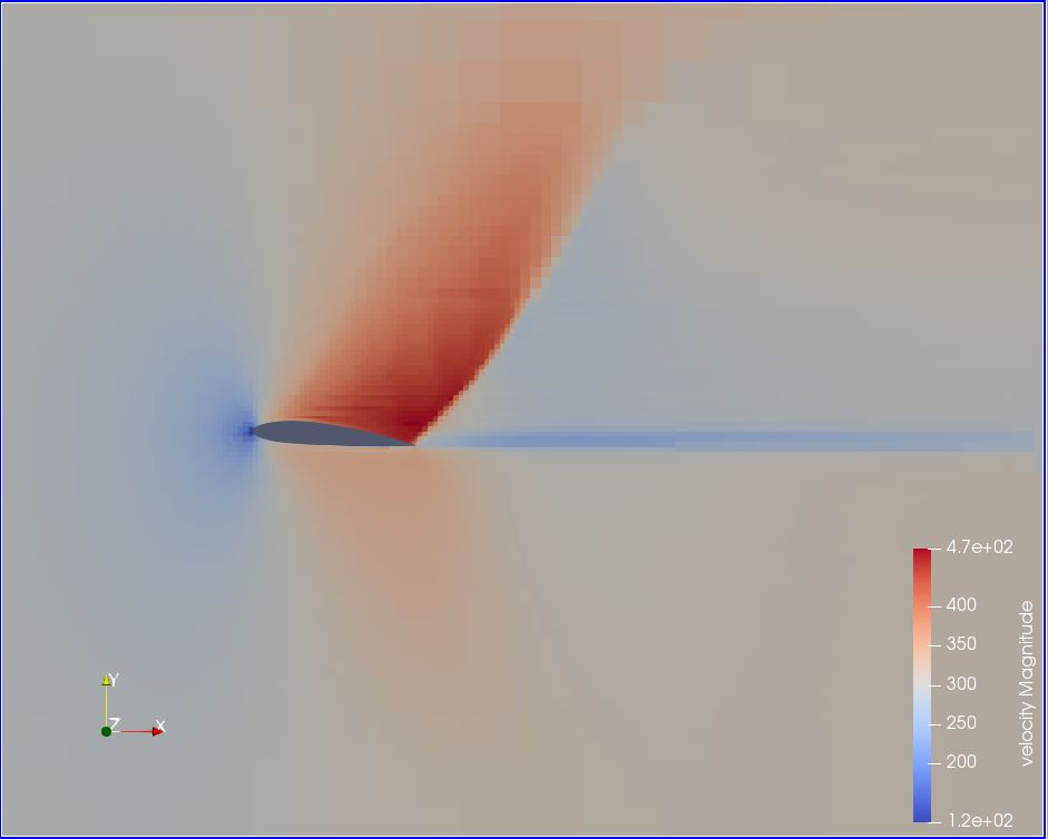
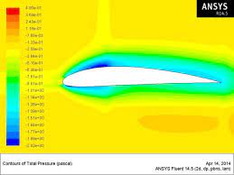
Here is the pressure and velocity profile for Naca 2421
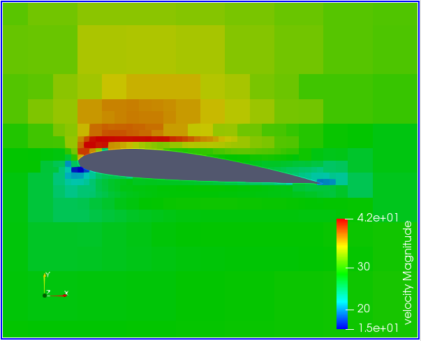
Here is the pressure and velocity profile for Naca 2415
Here is the pressure and velocity profile for Naca 2412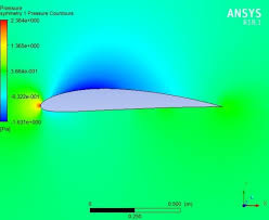
Data processing
Naca 2414
NACA 2414 airfoil has a maximum camber of 2%, located 40% from the leading edge with a maximum thickness of 14 % of the chord.
- Drag coefficient -32.7
- Lift Coefficient - 29.2
Naca 2421
NACA 2421 airfoil has a maximum camber of 2%, located 40% from the leading edge with a maximum thickness of 21 % of the chord.
- Drag coefficient - 23.8
- Lift Coefficient - 6.9
Naca 2415
NACA 2415 has a wing section having 2 percent camber at 40% from the leading edge, with thickness 15 % of the chord.
- Drag coefficient - 0.85
- Lift Coefficient - 0.7
Naca 2412
NACA 2412 airfoil has a maximum camber of 2% located 40% from the leading edge with a maximum thickness of 12% of the chord.
- Drag coefficient - 4.93
- Lift Coefficient - 1.69
Results
>>>>>>>>>>>>>>> | LIFT COEFFICIENT | DRAG COEFFICIENT |
|---|---|---|
Naca 2411 | 29.2 | 32.7 |
Naca 2421 | 6.9 | 23.8 |
Naca 2415 | 0.7 | 0.85 |
Naca 2412 | 1.69 | 4.93 |
Graph
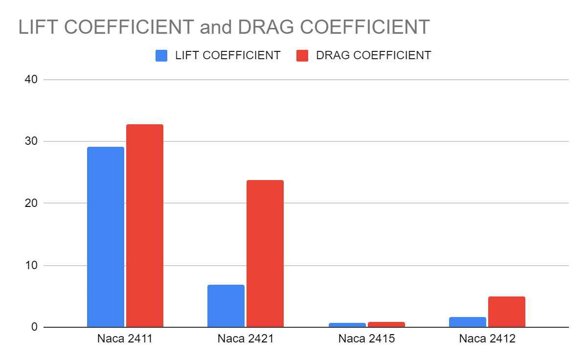
Graph Analysis
As you can see in the graph, Naca 2411 has more drag than any other aerofoil. This shows that Naca 2411 is the least efficient aerofoil to use. Naca 2415 produces less lift but also less drag. I would recommend using Naca 2412 because it has a good amount of lift and less drag.
Possible areas of inaccuracy
- Measuring the angle of attack in a wrong way or from a wrong angle.
- Different wind speeds for different Aerofoils.
Areas of difficulty
- Acquiring a wind tunnel.
- Making the aerofoil.
Conclusion
My hypothesis was proved right by showing that the change in camber of an aerofoil will affect the lift and drag coefficient. Thank you.
BIBLIOGRAPHY