Projection Grid vs Plane Grid
A plane grid is flat, local 2D Cartesian grid (X and Y or Easting and Northing).
A projection grid is a global or regional system (like UTM or State Plane) created by mathematically projecting a round globe onto a flat surface.
Plane Grid
Assumptions:
The world is flat
No curvature
No EDM refraction
That 1m = 1m
No scale distortion
Can be arbitrary coordinates
Does not need connecting to datum
Vertical is ‘straight up’
Orientation can be arbitrary or ‘approximate’ to North.
Projection Grid
3D to 2D Problem
A map projection is defined as an ordered system to convert the 3D surface of the modelled Earth, onto a 2D plane.
Why do we need to use Map Projections?
Presentation: A flat surface is easier to present on paper or a computer screen compared with a curved/complex surface.
Calculations: It is easier to compute differences in position on the plane vs distances on an ellipsoid.
It is IMPOSSIBLE to convert a 3D surface to a 2D flat plane without introducing distortions or ‘cutting’ the surface.
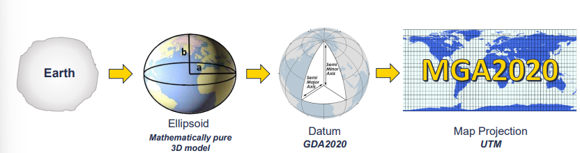
Universal Transverse Mertcator (UTM)
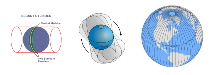
UTM is a transverse (turned on its side) cylindrical projection.
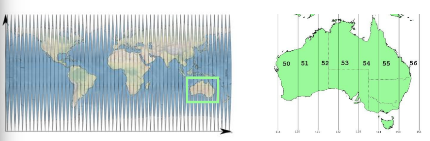
UTM projection is split into zones, with each zone being 6 degrees of longitude in width.
Plane <> Projection
Moving between projections
Plane > Projection
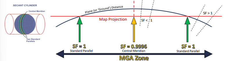
Computing the Point Scale Factor
For short distances (< 2 km), the scale factor is reasonably constant along the whole line therefore a single scale factor can be applied.
Scale factor on the central meridian: SF = 0.9996 (UTM/ MGA2020)
Equation:

Computing the Combined Scale Factor
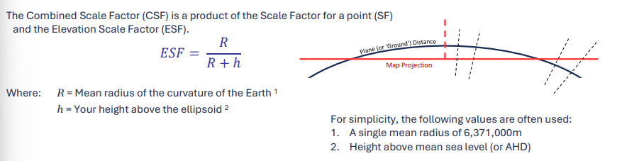
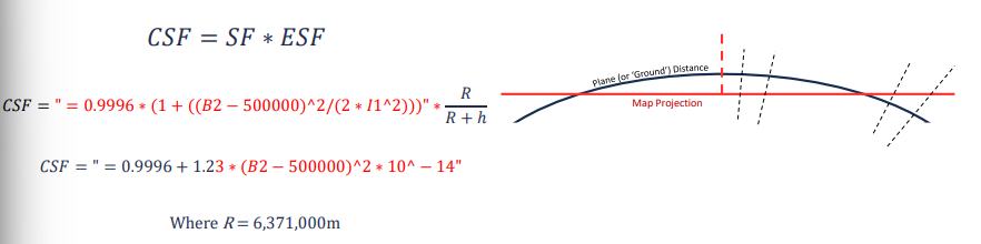
Example
STEPS:
Save the dataset with an appropriate name.
Decirde on the site centre
Decide if a single CSF is appropriate
Determine project CSF
Measure and record a long ‘check’ baseline in MGA
Save the project with a new appropriate name
Choose and record the origin point that you will scale the dataset around
Scale the dataset
Re-measure the ‘check’ baseline
Divide ‘check; baselines, the answer should equal the CSF
Check over and save the final dataset.
Avoiding Confusion
Are these coordinates MGA2020 (Projection) or scaled to ground distance (Plane)?
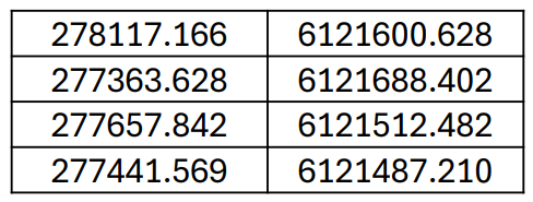
To remove the potential for confusion, it is good practice to apply a false easting and false northing to the coordinates so that when they are on the local plane.
False Easting and Northings:
In this example,we can create our ‘Plane Grid’ set of coordinates by subtracting 270,00 from the Eastings, and 6,120,000 from the Northings.

Reporting False Eastings and Northings
What information needs to be included within a survey report, or the datasets meta-data, to accurately communicate how to reverse engineer MGA2020 coordinates from a dataset that has been converted into plane grid coordinates with false eastings and nothings applies?
Essential Information:
Site Origin (point at which the dataset has been scaled about)
Combined Scale Factor (CSF) used when scaling from Projection to Plane grid
False Easting value applies.
False Northing value applied
Reference coordinates for control points in both Projection and Plane grid, these can then be used to check that the transformations has been applied correctly.