Finals AVI 412
TAIL ROTORS
The tail rotor, or anti-torque rotor, is crucial for providing directional control to single main rotor helicopters.
The absence of the tail rotor led to the development of alternative helicopter designs, including:
coaxial main rotors
tandem rotors
transverse rotors
intermeshing main rotors
Types of Tail Rotors:
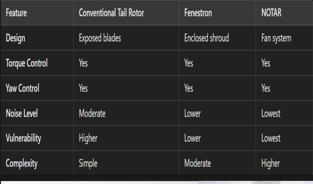
Conventional
Exposed blades rotating in a horizontal plane at the tail end of the helicopter.
Fenestron
Enclosed tail rotor system with blades housed in a circular shroud.
NOTAR
Utilizes a fan system located in the tail boom that directs air through a slot, creating a counteracting force without a traditional rotor.
The tail rotor, like the main rotor, needs to adjust pitch and flap either independently or together for proper operation.
Its blades must allow for both negative and positive pitch adjustments to ensure directional control during powered flight and autorotation.
Tail Rotor drive System
The tail rotor is driven by the helicopter's
transmission and must rotate at all times during flight, even if the engine is off.
It can be powered by the engine or by the transmission during autorotation.
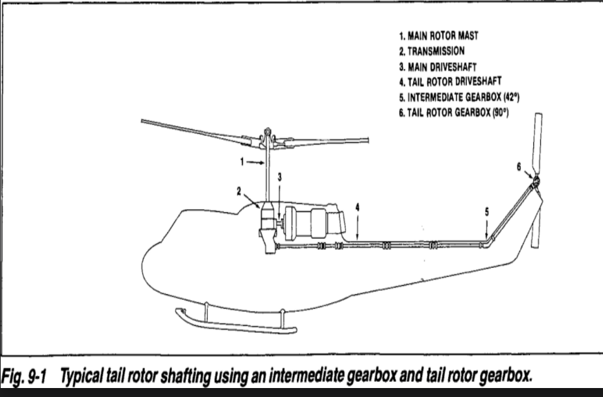
Main Rotor Mast
Transmission
Main Driveshaft
Tail Rotor Driveshaft
Intermediate Gearbox (42*)
Tail Rotor Gearbox (90*)
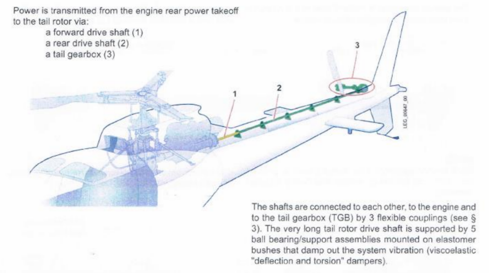
Power is Transmitted from the engine rear power takeoff to the tail rotor via:
Forward drive shaft
Rear drive shaft
Tail gearbox
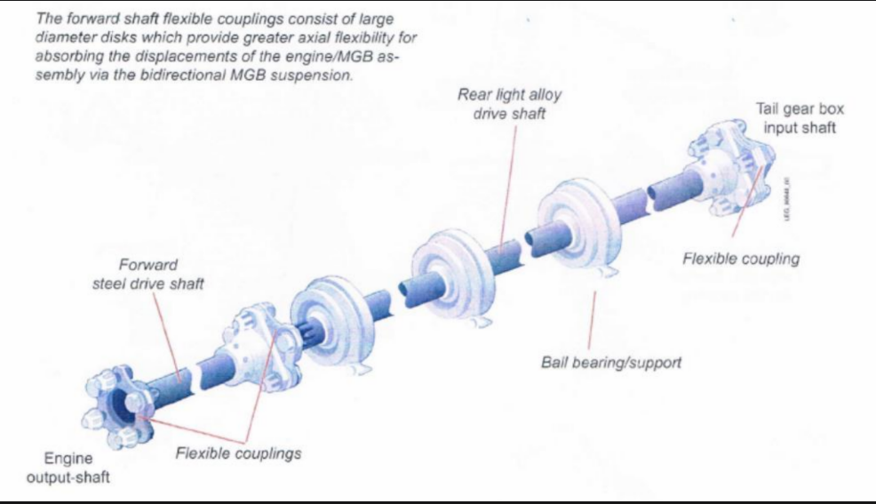
Shafts are connected to each other, to the engine and to the tail gearbox (TGB) by 3 flexible couplings. The very long tail rotor drive shaft is supported by 5 ball bearing/support assemblies mounted on elastomer bushes that damp out the system vibration (viscoelastic “deflection and torsion” dampers)
Tail rotor gearbox
The tail rotor gearbox changes the direction of rotation and can adjust the tail rotor's speed, which usually rotates faster than the main rotor.
Some helicopters have tail rotor speeds exceeding 3000 RPM.
Pitch-change mechanism
Most newer helicopters use push-pull tubes for tail rotor control, while a few utilize cables.
The pitch-change system may also feature hydraulic assistance, shared with the cyclic and collective controls.
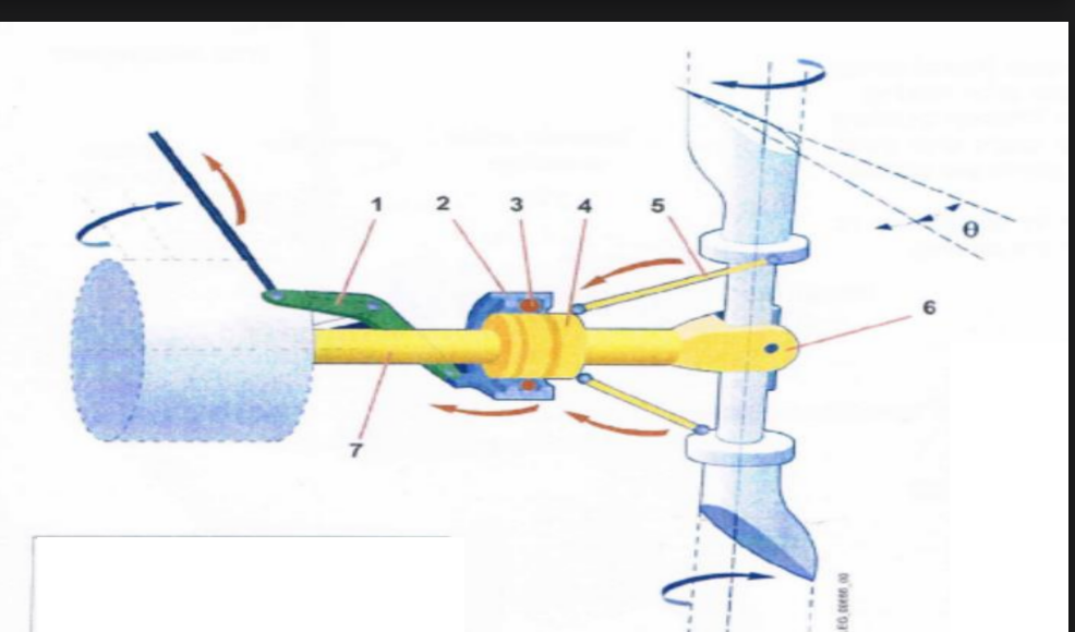
Rotating plane (4) - drive by rotor via 2 pitch change links
Pitch change links (5) - free to slide along the rotor shaft (7)
Stationary plate (2) - actuated by a pitch change bellcrank (1) hinged on TGB casing. Free to slide axially and hence moves the rotating plate but it is prevented from rotating by the bellcrank.
The stationary and rotating plates are separated by the ball bearing.
• 8.1 Operation, Tail rotor system, AStar 350, 8.2 Servicing, Tail rotor track, System rigging
Servicing
Servicing on newer helicopters has decreased significantly due to permanently lubricated bearings, while many older models require grease, with lubrication intervals and grease types specified by the manufacturer.
Temperature
A temperature rise in the bearing package indicates potential failure, often accompanied by high-frequency vibrations.
For unenclosed shafts, post-flight inspections require manual temperature checks of the bearings.
Driveshaft Inspection
Enclosed shafts may use heat-sensitive stickers on bearings for quick visual monitoring of temperature increases.
Driveshafts made of aluminum alloy need minimal maintenance but are prone to corrosion, scratches, and bends.
Maintenance should follow manufacturer guidelines for addressing these issues, with special attention during inspections at stressed
Couplings
Different couplings may be used at various locations on an aircraft, and some types can be interchangeable.
Grease is commonly used for lubricating couplings, and methods may include hand packing or using a grease gun.
Alignment
Proper alignment is essential to prevent excessive vibration and wear, particularly in bearing areas.
Newer helicopters are typically aligned during manufacture using permanently bonded shims, while older models may need alignment and runout checks, with shimming of hanger bearings to correct alignment issues.
The tail rotor experiences high-frequency vibrations, which pilots often feel in the pedals, leading to discomfort in their feet.
If changing the tail rotor pitch increases the vibration, the issue is likely with the pitch change mechanism or tail rotor.
If not, the problem usually lies in the drive train.
Tail Rotor Track
Balancing the tail rotor, like the main rotor, occurs after ensuring it is properly tracked, which can be done manually or electronically.
Some helicopters may not allow for track adjustments, making accurate tracking during initial setup essential. Helicopter airframes use diverse materials, reflecting technological advances over 40 years.
These materials are largely the same as those in fixed-wing aircraft.
Types of Airframe Construction
• Tubular Construction
• Sheet metal Construction
• Bonded Construction
TUBULAR CONSTRUCTION
High strength-to-weight ratio, making it structurally efficient.
Manufacturing is labor-intensive, involving precise cutting, fitting, and welding of tubes.
Easily repaired in the field unless severely damaged.
SHEET METAL CONSTRUCTION
Sheet metal construction (monocoque/semi monocoque) has a higher strength-to-weight ratio than tubular construction.
Manufacturing is faster with stamped parts and better tolerances.
Field repairs are simpler, but large repairs need jigs for proper alignment.
JIGGING
“jigging" refers to the process of using specialized tools, fixtures, or templates known as jigs to ensure the accurate and consistent assembly or manufacturing of aircraft components.
BONDED CONSTRUCTION
Materials like fiberglass and honeycomb structures are lightweight yet strong, making them ideal for aerospace applications.
Bonded structures reduce the need for labor-intensive riveting and welding, lowering manufacturing costs while maintaining structural integrity.
STRESS AND LOADS
Helicopters handle both lift and thrust at the main rotor, unlike fixed-wing aircraft with separate stress points.
Helicopter centers are heavily reinforced to handle combined loads.
Inspect and repair the center fuselage, the main load-bearing area.
LANDING
Helicopters typically carry landing loads in one direction, unlike fixed-wing aircraft, which handle loads in two directions due to forward landing speed.
Helicopters may face dual-direction loads during autorotation or tail rotor failure landings, requiring some structural reinforcement.
VIBRATION LEVELS
Helicopters have high vibrations due to rotating components.
Systems like bifilar and nodal beams help reduce vibrations.
Vibrations affect the entire airframe, requiring careful inspection.
TAIL SECTION
Provides directional and anti-torque control.
Tail boom carries side loads, with relief from the vertical fin and downward force from the horizontal stabilizer.
The tail boom, often cantilevered and attached to the fuselage, carries these loads, making the attachment areas critical for inspection.
WHEEL AND SKID GEAR
Skid Gear: Simple, low-maintenance, but more challenging for ground handling.
Wheel Gear: Easier to maneuver on the ground, allowing the helicopter to move under its own power.
Trade-off: Skid gear is more maintenance-friendly, while wheel gear provides better ground mobility.
VISIBILITY
Helicopters typically offer better frontal visibility than fixed-wing aircraft due to their flight characteristics and approach angles.
The unique angles helicopters can approach from enhance visibility, especially for tasks like hovering or landing.
The type of work helicopters do, such as aerial surveying or search-and-rescue, requires improved visibility for safety and efficiency.
Structural Components and Materials
The AS350 employs semi monocoque construction, a design where the outer skin and internal supports share structural loads, combining strength and efficiency.
The airframe is primarily made of lightweight materials like aluminum and thermosetting synthetic resins, chosen for their strength-to-weight ratio and durability.
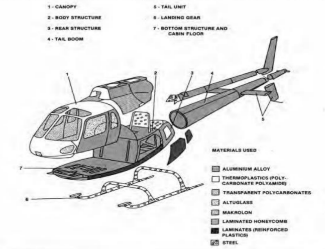
Canopy
Body structure
Rear structure
Tail boom
Tail unit
Landing gear
Bottom structure and cabin floor
Body structure
The body structure handles lift, thrust, and landing loads while supporting all other fuselage components.
Features an "X"-reinforced box for strength, with the transmission assembly attached to absorb landing forces.
Fuel tanks are centrally located for maximum protection within the structure.
Bottom structure
The bottom structure's cantilevered beams carry the cabin's weight and transfer it to the body structure.
Cross members reinforce the beams, supporting the floor and lower skin panels.
The cabin directly attaches to the floor for structural cohesion.
Cabin section
The cabin section is primarily made of polycarbonate reinforced with glass fibers for strength and durability.
Components are heat-molded and joined using banding and ultrasonic spot welding.
Upper, lower, and windshield windows are polycarbonate, valued for their exceptional strength.
Rear section
The rear section connects to the body via three frames and beams, forming a critical structural link.
The rear section's frame, covered with a stainless steel firewall, serves as the attachment point for the engine.
The interior of the rear section functions as a storage space, with the tail boom bolted to the rear frame for added stability.
Tail Boom
The tail boom has a conventional design with circular frames, stringers, and outer skin, with stringers providing rigidity.
The tail boom houses critical components, including the tail rotor gearbox, driveshaft, vertical fins, and horizontal stabilizer.
Extra stiffeners are added in areas of high stress, such as around the tail rotor and stabilizers, for added strength.
Vertical fin
The lower vertical fin is a symmetrical airfoil, protected from nose-up landing damage by a tail rotor guard.
The top fin is a dissymmetrical airfoil, used to correct main rotor torque during cruise flight by exerting force on the tail.
Both fins are bolted to the tail boom
Horizontal stabilizer
The horizontal stabilizer is a dissymmetrical airfoil, generating a downward force to help maintain level flight.
The stabilizer is set at a two-degree angle from the horizontal datum to ensure proper aerodynamic effect.
The stabilizer passes through a slot in the tail boom and is bolted securely on each side.
Skid gear
The skid gear includes components like rubber bushings and hydraulic dampeners to reduce ground vibrations during rotor operation.
The skid gear consists of a forward and rear cross tube, two skids, and hydraulic dampeners, ensuring stability and control.
The skids feature skid shoes and a downward-bent steel strip, which act as a vibration dampener to prevent ground resonance.
Anti vibration device
Located under the pilot's seat, this device uses a steel blade with a weight attached to create a node that cancels out vertical vibrations in the cabin.
The device resonates with the airframe vibrations to reduce discomfort and improve stability inside the helicopter.
The helicopter features a strong center section that supports the cabin and tail boom, integrating the anti-vibration effectively into the structure.
Airframe Systems
Fuel, electrical, ventilation, and climate systems are essential, similar to fixed-wing aircraft.
Systems are tailored for the helicopter's specific mission.
Systems are designed to work seamlessly with the airframe and rotor components.
Fuel system
Helicopter fuel systems typically use force-feed delivery with boost pumps, ensuring redundancy through dual pumps and check valves to prevent failures.
Essential components include the bladder fuel cell, centrifugal pumps, pressure switches, an electrically operated shutoff valve, and a fuel filter with a bypass caution light for safety and monitoring.
Electrical system
Turbine-powered helicopters, like the AS350, use starter-generators to both start the engine and generate power during flight.
These helicopters typically have two batteries for reliable starting, especially since ground power units are rarely used.
Commonly used in turbine helicopters for their durability and ability to handle high discharge rates needed for engine starts.
Environmental systems
Some helicopters now use environmental control units (ECUs), which are air cycle machines that provide either hot or cool air to the cabin.
ECUs regulate cabin temperature by either heating or cooling the air, improving passenger and crew comfort, particularly in varying environmental conditions.
The ECU functions like an air cycle machine, which uses compressed air to produce either heated or cooled air, depending on the requirements of the helicopter’s interior.
Special Purpose Equipment
Helicopters, like the AS350, can be fitted with special-purpose equipment such as high skid gear, pop-out floats, rescue hoists, cargo hooks, ambulance setups, and spotlights to adapt to diverse missions.
Manufacturers offer many items as optional equipment, while others are developed by third parties and certified through a Supplemental Type Certificate (STC) to ensure compliance with aviation standards.
Special-purpose equipment is often provided in kit form, tailored for specific helicopter models to meet operational needs effectively.
High skid gear
High skid gear is commonly used to raise the fuselage, reducing the risk of tail rotor strikes, especially in unimproved landing areas.
In Arctic regions, extra plates may be added to the skids to prevent them from sinking into soft tundra, providing a larger surface area for stability.
High skid gear is often available as optional equipment from the manufacturer, allowing helicopters to be customized for specific mission needs.
Floats
Emergency devices for overwater flights, requiring periodic inspection and pilot activation.
Used for regular water landings but limited flight performance.
Rare in civilian helicopters.
Rescue hoists
Rescue hoists are primarily used by civil agencies like police and fire departments for rescue operations.
They enable helicopters to lift light loads for rescue work.
The hoist acts as a platform for lifting and retrieving people or objects during emergency rescues.
Cargo hooks
Cargo hooks are used for lifting heavy external loads, such as sling loads, and are typically used in specialized operations.
They include both electrical and manual release systems for emergency jettisoning of the load.
External loads can exceed the helicopter's normal weight limits, and the cargo hook is ideally positioned near the center of gravity for balance.
Litter installations
Litter modifications can range from simple to extensive, involving change like cutting the door post for installation.
The modification requires structural integrity, including latch mechanisms to secure both the airframe and the litter.
These modifications are typically found in civil government and charter operations, especially for medical or rescue missions.
Light installations
Some helicopters are equipped with Xenon lights, commonly used in police work.
These lights are often controlled via the cyclic control, allowing tilt, rotation, and flood/spot adjustments.
Some Xenon lights can produce up to 65 million candlepower, providing intense illumination.
Spray equipment
Spray equipment is not made by the aircraft manufacturer but by specialized companies with an STC (Supplemental Type Certificate).
Some spray equipment is mounted directly on the aircraft.
Other spray units are self-contained and are connected to the helicopter via the cargo hook for use.
Stabilization devices
No helicopter is certified for IFR (Instrument Flight Rules) operations without stabilization equipment
These devices are either built alongside the helicopter or installed to assist pilots, particularly in non-IFR certified helicopters.
Stabilization systems have been used by the military for a long time, and with the rapid growth of the helicopter industry, specialized equipment will continue to evolve.