GEOM 4 (Jan 20th)
Typed
Datums and Earth Models, ellipsoids and Geoids
Datums
Identifying the size and shape of the geographic models we are using
Characteristics like:
Size
Shape
Ellipsoid
Origin and Orientation
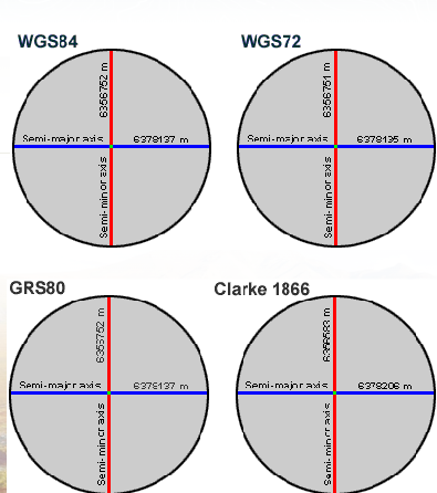
Common spheroids consist of
WGS84
WGS72
GRS80
Clarke 1866
Data captured on one spheroid will not be applicable to another
The differences between the models are significant, as each spheroid is based on different parameters such as flattening and semi-major axis, which impact geodetic calculations and the accuracy of positional data.
NAD27 and NAD83 common in North America
NAD83 preferred
Uses center of the earth as starting point
Many GPS systems use WGS8
North American Datum 1927 (NAD27)
Uses the Clarke 1866 spheroid
Reference point is located at Meades Ranch, Kansas
North American Datum 1983 (NAD83)
Uses GRS80 (Geodetic Reference System) spheroid
WGS 1984
Most recently developed datum
Earth centered, or geocentric, perspective
This is the datum used by all GPS satellites
Nearly identical to NAD83...therefore NAD83 is compatible with data collected in GPS using WGS84
Geographic Coordinate Systems: latitude and Longitude
Coordinate System
Once you have a datum, you also define the location of poles (axis points of revolution) and equator (midway circle between poles, spanning the widest dimension of the spheroid), and you then have enough information to create a coordinate grid for referencing the position of features on the spheroid.
When a datum is acquired the first stem is to identify the poles in the model. Additionally we have to identify where the equator is located
Cartesian Coordinate System
Most common system used to display spatial data, which utilizes three axes (X, Y, and Z) to represent points in three-dimensional space.
Based on orthogonal Coordinates
Uses an Origin, Eastings and Northings
Latitude and Longitude: calculating distances along a parallel
The distance along a line of longitude (meridian) between 1 degree of latitude (parallel) is always the same: 111 km. The distance along a line of latitude between 1 degree of longitude decreases as you move a way from the equator. This variation and associated distance along a parallel is easily calculated:
1 of longitude = 111 km x cos (latitude)
e.g. What is the distance of 1o of longitude along the 60th parallel?
distance = 111 x cos(60) = 111 x 0.5 = 55.5 km
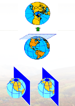
Projections
A map projection is the systematic transformation of locations on the earth (latitude/longitude) to planar coordinates
In GIS, the basis for this transformation is the geographic coordinate system (which references a datum)
Map projections are designed for specific purposes
Issues:
Geometric incompatibility between 3D earths surfaces and 2D hardcopy maps
Distortion of scale, area, distance, and direction can occur when representing the curved surface of the 3D Earth on flat 2D maps.
Shape
Area
Distance/Scale
Direction/Angle
Majority of the time, as one of the properties is correct, ont of the others is then misshaped
Categories of Projections
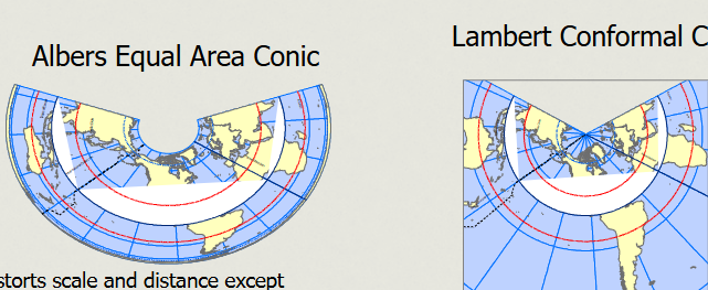
Conformal
Preserves the shape
The scale of the map is the same in all direction
Longitudes (meridians) and latitudes (parallels) intersect at right angles
Equivalent
Equal area – areas on the map have the same proportional relationships as areas on the Earth
Equidistant - preserves distance
Remember to compare maps in GIS, they must be in the same projection
Types of Projections
Conic: Best for mid-latitude regions, where the curvature of the Earth is minimized.
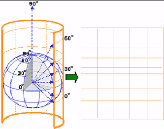
Cylindrical: Useful for global maps, but can distort size and shape near the poles.
Azimuthal: Preserves direction and is typically used for polar projections.
All of these can be presented and tangent or Secant
Cylindrical
Projects onto cylinder
preserve angles (directions)
Scales & Shape distortions increase away form central
Tangent: Cylinder is tangent to the sphere contact is along a great circle
Circle formed on the surface of the Earth by a plane passing through the center of the Earth
Conical
Projects onto cone
At tangent, contact along small circle
At secant, contact at 2 circles; one small, one great
Good projection for continental representation
Azimuthal
Projects spherical surface onto plane
At tangent, contact at a single point
At secant, contact at small circles with one great circle
AI
Semi-Major and Semi-Minor Axes
The terms semi-major axis and semi-minor axis refer to the two axes used to describe an ellipse. Their numerical values are not identical, which indicates the elliptical shape as opposed to a perfect sphere. Visually, one might interpret the dimensions in a misleading manner, but upon examining the values, it becomes clear that they differ.
WGS 84 and GPS
The WGS 84 (World Geodetic System 1984) is the default global coordinate system used by GPS (Global Positioning System). Modern applications on phones utilize WGS 84, which was also used in older handheld GPS receivers.
When exporting GPS data from a handheld device to a computer, WGS 84 serves as the reference system. Thus, any geographic data collected via GPS operates based on this coordinate system.
Comparison of WGS 84 and GRSA
In comparing WGS 84 with GRSA (Geodetic Reference System 1980), the differences in semi-major and semi-minor axes are minimal—less than 1 meter. This small deviation means both systems are considered compatible, allowing for effective data interchange.
When comparing WGS 84 semi-major axis values to those of GRSA, the crucial differences lie in the decimal points, which show that the measurements are closely aligned.
Comparison with Clark 1866
In contrast, the Clark 1866 model is distinctly different from WGS 84. For example, the semi-major axis of Clark 1866 leads to a difference of approximately 170 meters compared to WGS 84. This discrepancy can result in significant location errors—potentially up to 200 meters—as errors can propagate when combining data from various systems.
Clark 1866 uses a reference point located in Kansas, emphasizing how the choice of reference affects geolocation accuracy.
Need for Coordinate Systems
Geographic areas and their objectives dictate the choice of coordinate systems in mapping and data collection. For instance, in North America, NAD83 (North American Datum 1983) and NAD27 (North American Datum 1927) are crucial systems.
NAD83 is modern and compatible with WGS 84, meaning data collected under either system can interoperate without considerable error. Meanwhile, data collected under NAD27 may yield significant positional errors when mapped onto WGS 84 backgrounds.
Geographic Coordinate Systems
The geographic coordinate system establishes a 3D framework to locate features accurately. The coordinate system is structured around the Earth’s poles and the equator, with latitude defined as the angle created between a point on the Earth's surface and the equator, while longitude defines itself relative to the prime meridian in Greenwich, England.
Latitude varies from 0 degrees at the Equator to 90 degrees at the poles, while longitude runs from 0 degrees at the prime meridian to 180 degrees east or west. This system allows for clear delineation of any location on Earth using (latitude, longitude) coordinates such as (45°N, 75°W).
Importance of Reference Points
The choice of reference points fundamentally influences positional accuracy. For example, algorithms must adjust for potential errors stemming from using different datums when overlaying datasets using incompatible coordinate systems.
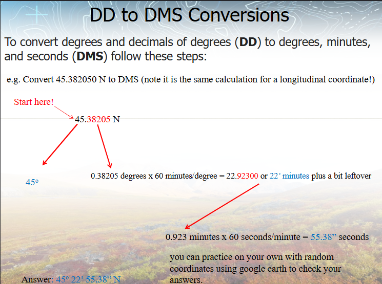
Practical Applications
Application software often necessitates transforming data between formats, such as converting degrees-minutes-seconds to decimal degrees and vice versa.
For instance, converting 45.38205° into DMS (degrees, minutes, seconds) format involves separating the integer part for degrees and using the decimal portion to determine minutes and seconds by multiplying by 60.
Conclusion
Understanding the differences in earth representation, coordinate systems, and the significance of selected datums is crucial for accurate geographic data analysis and application. Errors due to incompatible systems, such as NAD27 with WGS 84, highlight the need for awareness in data provenance and transformations, which can influence the effectiveness of geographical projects.